IAI ASEP Operation Manual
Controller
Hide thumbs
Also See for ASEP:
- Instruction manual (116 pages) ,
- First step manual (5 pages) ,
- First step manual (5 pages)
Table of Contents
Advertisement
Quick Links
Advertisement
Table of Contents

Related Manuals for IAI ASEP


Summary of Contents for IAI ASEP
- Page 1 ASEP Controller PSEP Controller Operation Manual Fourth Edition IAI America Inc.
-
Page 3: Important Information
In the case that you have any question or doubt in the contents of this Operation Manual, contact “IAI Customer Center Eight” or the nearest IAI sales offi ce. This Operation Manual shall not be used or copied, in whole or part, without our written... -
Page 5: Table Of Contents
Contents Safety Guide ......................1 Precautions in Operation ..................9 1. Product Check ....................15 1.1 Parts (The option is excluded.) ....................15 1.2 Teaching Tool (Option) .......................15 1.3 Operation manuals related to this product, which are contained in the operation manual (CD)............16 1.4 How to read the model plate ....................16 1.5 How to read the model of the controller ................16 2. -
Page 7: Safety Guide
Safety Guide “Safety Guide” has been written to use the machine safely and so prevent personal injury or property damage beforehand. Make sure to read it before the operation of this product. Laws and Standards for the Industrial Robots For the safety measures for the mechanical system, generally the following four measures are specified based on the International Industrial Standards ISO/DIS12100 “Safety for Machinery”. - Page 8 Requirements for the Industrial Robots set forth in the Ordinance on Industrial Safety and Hygiene Operation Operation Interruption of Treatment Specified in Area Condition Driving Source Out of Signal for operation startup Article 104 In Automatic Moving Disable Fence or enclosure Item 4 in Operation Range...
- Page 9 Our Models regarded as Industrial Robots The products which come under the following conditions, are excluded from the Industrial Robot category according to the notice from the Ministry of Labor and the notification issued by the director general of the Labor Standards Bureau in the Ministry of Labor (No. 340). (1) Single-axis robot product with the motor wattage of 80W or less (2) Multi-combined shaft robot product with the length of X, Y, and Z-axis of 300 mm or less and, if there is any rotary section, the maximum movable range is 300 cubic mm or less including the...
- Page 10 Safety Precautions for Our Products The common safety precautions for the use of any of our robots in each operation. Also, read the Operation Manual for each of other products. Operation Precautions Description Model Selection This product has not been planned and designed for the application where high level of safety is required, so the guarantee of the protection of human life is impossible.
- Page 11 Operation Precautions Description Installation and (1) Installation of Robot Main Body and Controller, etc. Startup Make sure to securely hold and fix the product (including the work). A fall, drop or abnormal motion of the product may cause a damage or injury.
- Page 12 Operation Precautions Description Installation and (4) Safety Measures Startup When the product is under operation or in the ready mode, take the safety measures (such as the installation of safety and protective fence) so that nobody can enter the area within the robot’s movable range.
- Page 13 Operation Precautions Description Check Operation After the teaching or programming operation, perform the check operation one step by one step and then shift to the automatic operation. When the check operation is to be performed inside the safety protective fence, perform the check operation using the previously specified work procedure like the teaching operation.
- Page 14 Alert Indication The safety precautions are divided into “DANGER”, “WARNING”, “CAUTION” “NOTICE” according to the warning level, as follows, and described in the Operation Manual for each model. This indicates an imminently hazardous situation which, if the Danger product is not handled correctly, will result in death or serious Danger injury.
-
Page 15: Precautions In Operation
Precautions in Operation Pay attention to the following items. Danger [General] Do not use this product for the following applications: Medical equipment used to maintain, control or otherwise affect human life or physical health Mechanisms and machinery designed for the purpose of moving or transporting people Important safety parts of machinery This product has not been planned or designed for applications requiring high levels of safety. - Page 16 If the LEDs on the product do not illuminate after turning on the power, turn off the power immediately. The protective device (fuse etc.) on the live side may remain active. Request repair to the IAI sales offi ce from which you purchased the product.
- Page 17 Do not hold the moving parts of the product or its cables during installation. It may result in injury. Always use IAI’s genuine cables for connection between the controller and the actuator. Also, use IAI’s genuine products for the key component units such as the actuator, controller and teaching pendant.
- Page 18 When the product becomes no longer usable or necessary, dispose of it properly as an industrial waste. IAI shall not be liable whatsoever for any loss or damage arising from a failure to observe the items specifi ed in “Safety Precautions.”...
- Page 19 Other IAI shall not be liable whatsoever for any loss or damage arising from a failure to observe the items specifi ed in “Safety Precautions.”...
-
Page 21: Product Check
Note : The contents of this Operation Manual are the same as those of the Operation Manual attached to the product. [* For warranty period and warranty range, refer to the ASEP/PSEP Operation Manual on the Operation Manual CD.] Product Check This product is comprised of the following parts if it is of standard confi... -
Page 22: Operation Manuals Related To This Product, Which Are Contained In The Operation Manual (Cd)
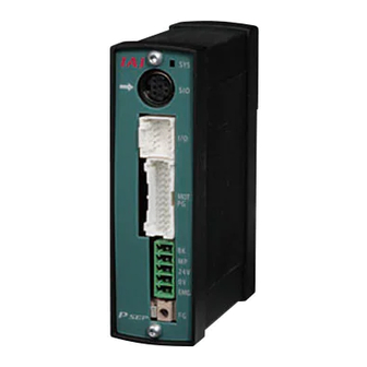
1.3 Operation manuals related to this product, which are contained in the operation manual (CD). Name Manual No. ASEP/PSEP Operation Manual (This Manual) ME0216 Touch panel teaching tool specially for PSEP/ASEP SEP-PT ME0217 PC Software RCM-101-MW/RCM-101-USB Operation Manual ME0155 1.4 How to read the model plate Model PSEP-C-20PI-NP-0-0 Serial number 800061910 1.5 How to read the model of the controller [ASEP] A S E P - C - 2 0 I - N P - 0 - 0 - A B U <Applicable to Simplified Absolute Unit>... -
Page 23: Basic Specifi Cations
For the data entry for the movement position and pressing force settings, easy entry from the optional PC Software unit (Model No. RCM-101-***) or touch panel teaching unit (Model No. SEP- PT) is available. Specifi cations Specifi cation Item ASEP PSEP Number of controlled 1-axis axes Power-supply voltage 24VDC±10%... - Page 24 Specifi cation Item ASEP PSEP RCA,RCP2, All type 800Pulse/rev RCP3 RCA2-□□□N 1048Pulse/rev RCA2 Encoder Except for RCA2-□□□N 800Pulse/rev Resolution RA1L·SA1L·SA4L·SM4L 715Pulse/rev RA2L·SA2L·SA5L·SM5L 855Pulse/rev RA3L·SA3L·SA6L·SM6L 1145Pulse/rev Positioning Command Number of positioning points 2 to 4 points Save the position data and parameters onto the non-volatile memory. (Serial...
-
Page 25: External Dimensions
External Dimensions [ASEP/PSEP] [Absolute Battery Unit(SEP-ABU)(Option)] Front View Side View Front View Side View 100mm 100mm 30mm 66.2mm 30mm 66.2mm Bottom View Bottom View [Dust-Proof Cover (Option)] Front View Side View 107mm 34mm 99.7mm Bottom View... -
Page 26: Installation Environment
Installation Environment Do not use this product in the following environment. • Location where the surrounding air temperature exceeds the range of 0 to 40°C • Location where condensation occurs due to abrupt temperature changes • Relative humidity less than 10%RH or greater than 85%RH •... -
Page 27: Installation And Noise Eliminati
Installation and Noise Elimination Noise Elimination Grounding (Frame Ground) Other Controller equipment Other Other Controller equipment equipment Connect it using an earth cable made of soft copper with the diameter of AWG16 (1.25mm Do not share the ground wire with or connect to other equipment. -
Page 28: Heat Radiation And Installation
Heat Radiation and Installation Conduct design and manufacture in consideration of the control box size, controller layout and cooling in such a way that the temperature around the controller will be 40°C or less. 20mm 50mm or more DIN Rail Spacer : PFP-S(OMRON) 1 Unit 20mm... -
Page 29: Wiring
Wiring • Connection Example Touch panel teaching tool LED for Absolute Battery STATUS monitoring specially for PSEP/ASEP (For the absolute type) *It can not be connected to SIO converter. LED for STATUS Absolute Battery Unit SIO Connector SEP-ABU Host System(PLC) -
Page 30: Led Indication
LED indication LED for STATUS teaching Indication Status Description Green Light is turned ON. Servo ON Status Green Light is turned OFF Servo OFF Status Flashing in green (1Hz) Servo-motor Auto OFF condition Red Light is turned ON. In the alarm issue or emergency stop Red Light is turned OFF Normal LED for Absolute Battery STATUS monitoring (in the case of Simplifi... -
Page 31: Power Connector
Power Connector Pin No. Signal Description Remarks For BK Release • Applicable Cable Motor Driving Power Supply Stranded Cable:0.3mm 1.25mm Positive side of the 24V power (AWG24 to AWG16) supply • Standard Cable Cover Peeling Negative side of the 24V power Off Length 7mm supply •... -
Page 32: Pio Connector
Backward End Position Detection Dedicated Position Detection (LS0) Cable (LS0) Forward End Forward End Position Detection Position Detection (LS1) ASEP, PSEP Solenoid (LS1) Solenoid Backward End Backward End Movement Signal Movement Signal (ST0) (ST0) Forward End Forward End Movement Signal... - Page 33 Position Detection Position Detection Cable [Target Position Setting cylinder. (LS0) (LS0) P(Air) Forward End Forward End (Position Data) Change] The change-over between ASEP, PSEP Position Detection Position Detection (LS1) (LS1) Movement the positioning and Movement Signal Signal (ST0) (ST0) pressing operations during...
- Page 34 The pressing operation is available. (Note) The air cylinder circuit is described with the symbols for the signals corresponding to those in ASEP/PSEP. Refer to the next page for the details of each signal.
- Page 35 • PIO Connector Signal Allocation to Each PIO Pattern Pattern Point-to-Point Point-to-Point Point-to-Point Reciprocating 3-Point 3-Point Point-to-Point Movement Movement Movement Movement Movement Movement (Movement (Target Position (Continuous (standard) (2-Input) (3-Input) Speed Setting) Setting Change) Reciprocating Operation) Cable Input/ Pin No. Single Double Single...
- Page 36 • Details of Each I/O Signal Signal Symbol Signal Name Function Type I/O Power supply+ It is the common power source for I/O circuit. The positive (+) side of DC24V is connected. Power Input I/O Power supply− It is the common power source for I/O circuit. The positive (−) side of DC24V is connected.
- Page 37 Signal Symbol Signal Name Function Type Backward End Position The same operation as of the limit switch of the air cylinder is performed. Input Detection It is turned ON when the current position is within the positioning width for each position detection output. Forward End Position Detection Intermediate Point Detection...
- Page 38 Power supply Output in PLC Input in PLC PIO Connector OUT0 OUT1 OUT2 OUT3 ASEP, PSEP... nth Unit Power supply Connector Brake Power Source When it is turned ON, the brake is released. Motor Power Unit Control power supply Emergency-stop input...
-
Page 39: Setting
“Double” (double solenoid system). System) Stop Signal Enable/Disable It is selectable only when “Single” is selected in “2. (Disable) Operation Mode (Solenoid System)”. ○ ○ ○ ○ When the PAUSE signal (*STP) is used, select “Enable”. Input Signal Continuous It is selectable only when “Double” is selected in “2. System Operation Type Operation Mode (Solenoid System)”. (Solenoid /Momentary For the signal sent from PLC to ASEP or PSEP, select ○ ○ ○ ○ Type) Operation Type “Continuous Operation” (level signal) or “Momentary (Continuous Operation” (edge signal). Operation Type) Intermediate Both Solenoids ON It is selectable only when the PIO pattern is set to “3”. Stop System /Both Solenoids In the case the same use procedure as for 5-port 3-position electromagnetic valve is applied, select “Both (Both Solenoids Solenoid OFF”. - Page 40 PIO Pattern Setting Range Setting Items Contents (Set in delivery) Output Signal Limit Switch The actuator is moved and the signal output system after Type /Positioning the positioning completion is selected. (Limit Switch) •Limit Switch : When the actuator reaches the target position, it is turned ON.
- Page 41 Position Data 5) Pressing 5) Pressing Position Data 1) Position 2) Velocity Energy-Saving Acceleration Deceleration Force Width Function Forward End Position 200.00 50.00 1.00 Effective Backward End 0.00 50.00 Effective Position Intermediate Point 100.00 50.00 Effective Position 1) Position … Set the position where the actuator is moved. Setting Range : 0 to Actuator Stroke Range (Unit 0.01mm) Set Position Operation Pattern Name...
- Page 42 6) Energy-Saving Function … When it is set to “Enable”, the servo-motor is turned OFF automatically after the positioning is completed and the specifi ed time period passes. (Because the holding current does not pass in the stop mode, the power consumption can be saved).
-
Page 43: Timing Chart
11. Timing Chart [1] Power Input → Operation preparation end 1) Release the emergency stop status or enable the motor driving power supply. 2) Supply 24VDC for the I/O. 3) Supply 24VDC for the controller. 4) Input the Servo-motor ON signal from the PLC side *3. 5) Input the backward end movement command and signals at fi... - Page 44 [3] Point-to-Point Movement (For Double Solenoid System) ••• PIO Pattern 0 to 2 With the combination of ST0 and ST1, the actuator is moved to the target position. ∗ ∗ Backward End Movement Signal (ST0) Forward End Movement Signal (ST1) Backward End Position Detection Output (LS0) Forward End Position Detection Output...
- Page 45 [6] Speed change during the movement (For Single Solenoid System) ••• PIO Pattern 1 The movement speed is changed during the actuator’s movement to the target position. When the movement command is issued with SPDC turned ON, the actuator is moved at the changed speed specifi...
- Page 46 [9] Target Position Setting Change (For Double Solenoid System) ••• PIO Pattern 2 When the operation is to be performed with the two types of works set differently each other, the setting change is easy by means only of sending a single signal from PLC. When the movement command is issued after CN1 is turned ON, the actuator is moved using the Position Setting 3, in the case of moving to the forward end.
-
Page 47: Starting Procedures
12. Starting Procedures When using this product for the first time, make sure to avoid mistakes and incorrect wiring by referring to the procedure below. No→ Check of Packed Items Contact our distributor or us. Are there all the delivered items? ↓Yes Installation and Wiring Point Check Item... -
Page 48: User Parame
13. User Parameters Name Initial Value Setting Range Remarks Dependent on 0.01 to Dependent Set which position before the target position is regarded as Positioning Width [mm] Actuator on Actuator the positioning completion point. Dependent on 0.01 to Dependent Jog Speed [mm/sec] Set the movement speed in using the jog button. - Page 49 • Servo-Motor Gain No. No.3 • Velocity Loop Integrated Gain No.6 This parameter decides the responsibility to the This parameter decides the responsibility to the position control loop. velocity control loop. When the set value is increased, the follow-up When the set value is increased, the follow- ability to the position command becomes better.
-
Page 50: Alarm Codes And Trouble Shooting
14. Alarm Codes and Trouble Shooting Code Alarm Name Cause/Treatment Movement Command in Cause : The movement command is input while the servo-motor is turned OFF. Servo-Motor OFF Treatment : Input “SON” signal to turn ON the servo-motor. Movement Command in Cause : The movement command is input while the home return has not been completed. - Page 51 Code Alarm Name Cause/Treatment For this controller, when the servo-motor is turned ON for the fi rst time after the power is input, the magnetic pole phase detection (pole sensing) is performed. However, the specifi ed encoder signal level is not detected after the excitement for the specifi...
- Page 52 Code Alarm Name Cause/Treatment Cause : (1) The temperature inside the controller is too high. (95°C or more) (2) When the actuator is vertically installed, in the case that the deceleration setting is too high when it is moved downward, the regenerative resistance energy might be insuffi cient. Overheat (3) The defective part inside the controller is considered.
- Page 53 Code Alarm Name Cause/Treatment A or B-phase Wire The encoder signal is not detected normally. Breakage Cause : A looseness or wire breakage in the connector section of the actuator connecting cable is considered. A -phase Wire Breakage Treatment : Check for the connection condition of the actuator connecting cable and perform the continuity test. B-phase Wire Breakage If normal, contact our company.
-
Page 54: Appendix
Connection Cable. (Another sales) *** shows the cable length. Existing Robot Cylinder Series Applicable Controller (Example:050=5m) RCP2 CB-PSEP-MPA□□□ PSEP (Except for Compact Rotary Type) • Compact Rotary Type CB-RPSEP-MPA□□□ RCP2-RTBS RCP2-RTBSL RCP2-RTCS RCP2-RTCSL RCP3 CB-APSEP-MPA□□□ ASEP, PSEP Extension Cable : CB-APSEP-MPA□□□JY(JYP) RCA2, RCL CB-ASEP-MPA□□□ ASEP... -
Page 55: Warranty Period And Scope Of Warranty
• Defect caused by use of a part other than IAI’s genuine part. • Defect caused by an alteration or other change not approved by IAI or its agent. • Defect caused by an act of God, accident, fi re, etc. - Page 56 SHANGHAI JIAHUA BUSINESS CENTER A8-303, 808, Hongqiao Rd. Shanghai 200030, China TEL 021-6448-4753 FAX 021-6448-3992 website: www.iai-robot.com The information contained in this document is subject to change without notice for purposes of product improvement. Copyright 2009. Dec. IAI Corporation. All rights reserved. 09.12.
Need help?
Do you have a question about the ASEP and is the answer not in the manual?
Questions and answers