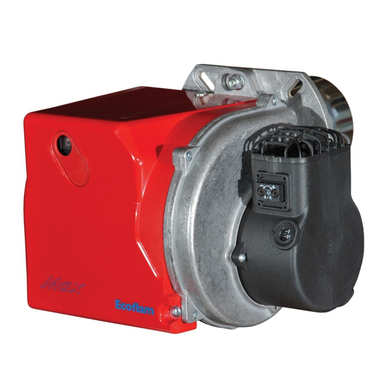
Ecoflam MAX 1 Manual
Light oil burners
Hide thumbs
Also See for MAX 1:
- Manual (28 pages) ,
- Operating instructions manual (23 pages) ,
- Manual (72 pages)
Subscribe to Our Youtube Channel
Summary of Contents for Ecoflam MAX 1
- Page 1 LIGHT OIL BURNERS MAX 1 Technical data Operating instructions Electric diagrams Spare parts list MAX 1 TC B10 230-50-60 TW 3142915 MAX 1 TL B10 230-50-60 TW 25-02-2021...
- Page 2 Overview - Index of contents Conformity declaration Technical data Working diagram Dimensions Operating instructions for authorised specialists 7 - 18 Electric diagrams Spare parts list 20 - 21 www.ecoflam-burners.com 420010518600...
- Page 3 Overview - Conformity declaration 420010518600 www.ecoflam-burners.com...
- Page 4 Overview - Technical data Technical data MAX 1 41,4 17,6 Burner output max/min kW - kcal/h 35604 15136 Oil throughput max/min kg/h Hydraulic system 1 stage Regulating ratio Light oil (L.C.V. 10.200 kcal/kg max. visc 1,6÷6 mm /s at 20°C)
- Page 5 Overview - Working diagram mbar MAX 1 kcal/h*1000 kg/h Working diagram The working diagram shows burner output as a function of combustion chamber pressure. It corresponds to the maximum values specified by EN 267 measured at the test fire tube.
- Page 6 Overview - Dimensions MAX 1 Model MAX 1 126,5 151,5 MAX 1 Boiler plate drilling Ø a Model Ø a Ø b Ø c MAX 1 126,5 151,5 Ø b Ø c Packaging Model MAX 1 www.ecoflam-burners.com 420010518600...
- Page 7 Notes for the operator was ordered. If in doubt, contact the The system should be inspected by a Ecoflam burners have been designed and manufacturer. specialist at least once a year. It is built in compliance with all current advisable to take out a maintenance regulations and directives.
- Page 8 Thermowatt KIT & ACS delivered separately Scope of delivery CB: COMPLETE BURNER - 1 bag including : - multilanguage technical manual. - filter and hoses. - wieland plug. - nozzle and spanner. - screws, nuts and washer. 103B www.ecoflam-burners.com 420010518600...
- Page 9 Pre-heater (version R) Burner motor Ignition transformer Solenoid valve Blower / Fan Oil pump Air damper Oil pressure regulator Hoses Filter Nozzle 420010518600 www.ecoflam-burners.com...
- Page 10 RJ45 - Connector for PC interface Symbol Designation (diagnostic, separate item). Waiting for heat request Waits for pre-heater (for burner with pre-heater) Burner motor on Start of ignition KIT E-BCU DIAGNOSTIC TOOL (not supplied) Flame present LINE 4’ < 400s < 1s www.ecoflam-burners.com 420010518600...
- Page 11 An eventual obstraction could damage the pump sealing device. Hoses ONE PIPE SYSTEM: If the oil supply Filter circuit is one-pipe system, the pump Oil cock needs to be modified following intructions Plug in the picture. 420010518600 www.ecoflam-burners.com...
- Page 12 Reverse flame boiler : A = 50-100 mm. Three pass boilers : A1 = 50-100 mm. Exhaust system To avoid unfavourable noise emissions, right-angled connectors should not be used on the flue gas side of the boiler. www.ecoflam-burners.com 420010518600...
- Page 13 • The heat request must be available. • All electrical connections must be correct. • Fuel tanks must be full. • The heat generator and heating system • The fuel supply lines must be 420010518600 www.ecoflam-burners.com...
- Page 14 1100m Theoretical H = 1m actual H 2m, Corrected H for suction 2 + 1 = 3m Corrected H for charging 2 - 1 = 1m. Choose the Ø of the piping from the table, based on the length expanded between the tank and pump. If corrected H for suction exceeds 4m; make provisions for a transfer pump (max. pressure 2 bar). www.ecoflam-burners.com 420010518600...
- Page 15 These values have been determined in achieved using the following nozzles: our test labs and are useful for the first Air damper setting (A). MAX 1 To act on the screw in figure: • to increase output, turn screwdriver clockwise •...
- Page 16 - Starting attempt with flame monitor unlit: malfunction after the restart and end of the automatic combustion control unit the safety time must switch to malfunction at the end of the safety time www.ecoflam-burners.com 420010518600...
- Page 17 (maintenance position 1). Nozzle and cleaning replacement Use only the suitable box wrench provided Max 1 for this operation to remove the nozzle, taking care to not damage the electrodes. Fit the new nozzle by the same care.
- Page 18 Check ignition circuit, electrode adjustment. Clean/replace electrodes. Clean/replace flame monitor. Replace the following items as required: Flame extinguishing Flame goes out during Ignition electrodes/ignition cables/ignition during operation operating phase transformer/nozzle/pump/solenoid valve/ automatic combustion control unit. www.ecoflam-burners.com 420010518600...
- Page 19 Overview - Electric diagrams 420010518600 www.ecoflam-burners.com...
- Page 20 Overview - Spare parts list www.ecoflam-burners.com 420010518600...
- Page 21 NOZZLE HOLDER SUPPORT 65320695 65320699 NOZZLE HOLDER 65320708 65320710 DIFFUSER 65320760 65324056 65320204 FLANGE 65325174 GASKET 65321071 AIR SELECTOR REAR DISC FAN SCOOP 65320505 65320506 PIPE GASKET 65321065 PIPE 65321508 TC = Short Head TL = Long Head R= Version pre-heater 420010518600 www.ecoflam-burners.com...
- Page 22 420010518600...
- Page 23 420010518600 www.ecoflam-burners.com...
- Page 24 Ecoflam Bruciatori S.p.A. reserves the right to make any adjustments, without prior notice, which is considered necessary or useful to its products, without affecting their main features Ecoflam Bruciatori S.p.A. si riserva il diritto di apportare ai prodotti le modifiche che riterrà necessarie o utili, senza pregiudicarne le caratteristiche principali.


Need help?
Do you have a question about the MAX 1 and is the answer not in the manual?
Questions and answers