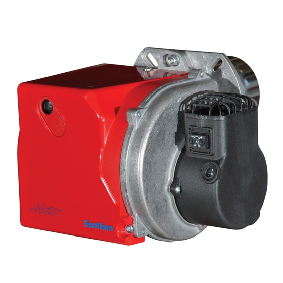
Ecoflam MAX 1 Operating Instructions Manual
Light oil burners
Hide thumbs
Also See for MAX 1:
- Manual (28 pages) ,
- Operating instructions manual (72 pages) ,
- Manual (24 pages)
Advertisement
LIGHT OIL BURNERS
Technical data
Dati tecnici
Données techniques
Datos técnicos
Operating instructions
Istruzioni per l'uso
Notice d'emploi
Manual de uso
Electric and hydraulic diagrams
Schemi elettrico e idraulico
Schémas électrique et hydraulique
Esquemas eléctrico e hidráulico
Spare parts list
Pièces de rechange
Parti ricambi
Piezas de recambio
MAX 1 / 1 R
MAX 4 / 4 R
MAX 8
MAX 12
MAX 1 TC
MAX 1 TL
MAX 1 R TC
MAX 1 R TL
MAX 4 TC
MAX 4 TL
MAX 4 R TC
MAX 4 R TL
MAX 8 TC
MAX 8 TL
MAX 12 TC
MAX 12 TL
www.ecoflam-burners.com
3142709
3142710
3142711
3142712
3142714
3142715
3142720
3142721
3142716
3142717
3142718
3142719
EN
IT
FR
ES
RU
Advertisement

Summary of Contents for Ecoflam MAX 1
-
Page 1: Operating Instructions
LIGHT OIL BURNERS www.ecoflam-burners.com MAX 1 / 1 R MAX 4 / 4 R MAX 8 MAX 12 Technical data Dati tecnici Données techniques Datos técnicos Operating instructions Istruzioni per l’uso Notice d’emploi Manual de uso Electric and hydraulic diagrams Schemi elettrico e idraulico Schémas électrique et hydraulique... - Page 2 Instrucciones de montaje para el instalador especialista 42 - 53 54 - 65 Electric diagrams Schemi elettrico Schémas électrique 66 - 67 Esquemas eléctrico Spare parts list Parti di ricambio Pièces de rechange 68 - 71 Piezas de recambio www.ecoflam-burners.com 420010370401...
- Page 3 Overview Panoramica Vue d'ensemble Descripción 420010370401 www.ecoflam-burners.com...
- Page 4 420010370401...
- Page 5 420010370401 www.ecoflam-burners.com...
-
Page 6: Table Of Contents
Ecoflam burners have been designed and built in compliance with all current regulations and directives. All burners comply to the safety and energy saving operation regulations within the standard of their respective performance range. - Page 7 230V/50-60Hz 230 Volt, 50-60 Hz KIT & ACS delivered separately Scope of delivery CB: COMPLETE BURNER - 1 bag including : - multilanguage technical manual. - filter and hoses. - wieland plug. - nozzle and spanner. - screws, nuts and washer. 103B 420010370401 www.ecoflam-burners.com...
-
Page 8: Oil Burner Pump
Pre-heater (version R) Burner motor Ignition transformer Solenoid valve Blower / Fan Oil pump Air damper Oil pressure regulator Hoses Filter Nozzle www.ecoflam-burners.com 420010370401... -
Page 9: E-Bcu Oil Control And Safety Unit
Burner motor 4 Preventilation: motor ON, ignition ON closes, burner stop OW Release contact of oil preheater 4’ Parasitic flame monitoring 9 Standby Control thermostat or pressurestat 5 Burner start: solenoid valve OFF, flame Ignition transformer production, safety time 420010370401 www.ecoflam-burners.com... - Page 10 An eventual obstraction could damage the pump sealing device. ONE PIPE SYSTEM: If the oil supply One-pipe system circuit is one-pipe system, the pump needs to be modified following intructions in the picture. DANFOSS SUNTEC www.ecoflam-burners.com 420010370401...
- Page 11 A as specified in the boiler manufacturer’s instructions must be observed. Exhaust system To avoid unfavourable noise emissions, right-angled connectors should not be used on the flue gas side of the boiler. 420010370401 www.ecoflam-burners.com...
-
Page 12: Checks Before Commissioning
• The heat request must be available. • All electrical connections must be correct. • Fuel tanks must be full. • The heat generator and heating system • The fuel supply lines must be www.ecoflam-burners.com 420010370401... -
Page 13: Oil Feeding And Suction Line
Two-pipe siphon feed system FEEDING LINE WITH DANFOSS BFP21 R3 Length pipe (m) H = x-y ø 6 mm ø 8 mm ø 10 mm Two-pipe lift system Length pipe (m) ø 6 mm ø 8 mm ø 10 mm 420010370401 www.ecoflam-burners.com... -
Page 14: Setting Data Table - Air Regulation
These values have been determined in achieved using the following nozzles: our test labs and are useful for the first Air damper setting (A). MAX 1 MAX 4-8-12 To act on the screw in figure: • to increase output, turn screwdriver clockwise •... - Page 15 - Starting attempt with flame monitor unlit: malfunction after the restart and end of the automatic combustion control unit the safety time must switch to malfunction at the end of the safety time 420010370401 www.ecoflam-burners.com...
- Page 16 A and B to the same height, tighten the set screw on the blower wheel Max 1 (maintenance position 1). Nozzle and cleaning replacement Use only the suitable box wrench provided for this operation to remove the nozzle, taking care to not damage the electrodes.
- Page 17 Check ignition circuit, electrode adjustment. Clean/replace electrodes. Clean/replace flame monitor. Replace the following items as required: Flame extinguishing Flame goes out during Ignition electrodes/ignition cables/ignition during operation operating phase transformer/nozzle/pump/solenoid valve/ automatic combustion control unit. 420010370401 www.ecoflam-burners.com...
- Page 18 420010370401...
- Page 19 420010370401 www.ecoflam-burners.com...
- Page 20 420010370401...
- Page 21 420010370401 www.ecoflam-burners.com...
- Page 22 420010370401...
- Page 23 420010370401 www.ecoflam-burners.com...


Need help?
Do you have a question about the MAX 1 and is the answer not in the manual?
Questions and answers