
Related Manuals for EdilKamin BILD Up


Summary of Contents for EdilKamin BILD Up
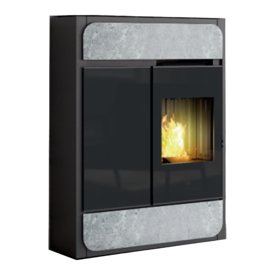
- Page 1 BILD PELLET STOVE For all updates visit www.edilkamin.com Installation, use and maintenance page...
-
Page 2: Table Of Contents
Troubleshooting Troubleshooting The original language of this manual is Italian The undersigned, EDILKAMIN S.p.A., with registered office in Via P . Moscati 8 - 20154 Milan (Italy) - Tax ID Code and VAT number 00192220192 Hereby declares, under its sole responsibility, that: the pellet stoves mentioned below comply with Regulation (EU) No. -
Page 3: General Information
• the declaration of conformity (or the documents www.edilkamin.com required in the country of installation) issued to you by the installer. Readers of this manual... - Page 4 DO NOT CLEAN THE COMBUSTION action, but contact the dealer or the installer. CHAMBER WITH A VACUUM CLEANER WHILE IT IS HOT. You could damage the The names of Edilkamin official authorised vacuum cleaner and risk letting smoke technical assistance...
-
Page 5: Dimensions - Technical Data
DIMENSIONS DIMENSIONS (cm) Ø 8 cm air channeling Ø 4 cm Combustion air Ø 8 cm Smoke outlet Ø 8 cm Smoke outlet USER/INSTALLER... - Page 6 2 kW Power absorption during ignition 375 W Remote control frequency (provided) 2,4 GHz Protection rating Fuse 4 AT, 250 Vac 5x20 EDILKAMIN S.p.A. The manufacturer reserves the right to modify the product without notification in the interests of improvement. USER/INSTALLER...
- Page 7 TECHNICAL DATA TECHNICAL DOCUMENTATION FOR LOCAL SPACE HEATERS ACCORDING TO COMMISSION REGULATION (EU) 2015/1185 AND 2015/1186 Manufacturer Edilkamin S.p.A. Trademak Edilkamin Model Identifier Bild - Bild Air Tight C Description Mechanically space heater fired by wood pellets Indirect heating functionality...
-
Page 8: Unpacking
UNPACKING PREPARATION AND UNPACKING PACKAGING The packaging materials are neither toxic nor noxious The packaging materials are neither toxic nor noxious The delivery consists of two packages: and do not require special disposal. and do not require special disposal. • one containing the stove frame The user is responsible for storing, disposing of and The user is responsible for storing, disposing of and... - Page 9 UNPACKING DO NOT TRY TO REMOVE THE PRODUCT FROM THE PALLET WITHOUT HAVING REMOVED THE LOWER PROFILE AND REMOVED THE SCREWS WHICH SECURE IT TO THE PALLET TO REMOVE THE STOVE FROM THE PALLET follow the images below To remove the stove from the pallet 1.
- Page 10 UNPACKING at the rear, unscrew the fastening bracket THE DRAWINGS ARE FOR GUIDANCE ONLY, USEFUL FOR THE INSTALLATION, BUT THEY MAY NOT REFER TO THE SPECIFIC MODEL. INSTALLER...
- Page 11 ORIENTATION OF THE SMOKE OUTLET SMOKE OUTLET SMOKE OUTLET The stove is delivered with the fume discharge pipe outlet on the top. The stove is delivered with the fume discharge pipe outlet on the top. To use the rear smoke outlet we provide an optional which can be found in our stores. To use the rear smoke outlet we provide an optional which can be found in our stores.
-
Page 12: Installation
The room must have a volume of at least 30 m appliance off. • The floor must be able to bear the weight of the Contact the authorised Edilkamin Technical Assistance product and its accessories* (see the note in the Centre. paragraph on heat protection). - Page 13 INSTALLATION FLUE SYSTEM FLUE SYSTEM THE SMOKE DUCT THE SMOKE DUCT ( ( Fumes duct, flue and chimney pot Fumes duct, flue and chimney pot) ) In addition to the general requirements for the fume This chapter has been drawn up pursuant to European duct and the flue, the fume duct: : regulations EN 13384, EN 1443, EN 1856 and EN •...
- Page 14 INSTALLATION THE FLUE THE FLUE: EXTERNAL AIR INTAKE In addition to the general instructions applicable to the In general, we suggest two alternative ways for ensuring fume duct and the flue, the flue: : a proper flow of indispensable combustion air. •...
- Page 15 The electrical system must be compliant; check the operation of the earth in particular. Edilkamin is not responsible for malfunctions resulting from an improperly earthed system. The power line must be of adequate section for the power of the appliance.
-
Page 16: Cladding
STONE AND CERAMIC CLADDING Description Reference in the Quantity figures below Front panel (ceramic or stone) For ceramic series: Black D4 washer M4 thumb screw For stone series: Flat D5 washer M5 screw THE DRAWINGS ARE FOR GUIDANCE ONLY, USEFUL FOR THE INSTALLATION, BUT THEY MAY NOT REFER TO THE SPECIFIC MODEL. - Page 17 STONE AND CERAMIC CLADDING Fitting of the stone or ceramic lower front panel Screw the stone or ceramic front panel onto the lower front panel (this was removed previously to remove the product from the pallet) Fit the assembled front panel onto the structure, inserting it into the lower hooks and screwing in the screws above. There are no adjustments to be made INSTALLER...
- Page 18 STONE AND CERAMIC CLADDING Fitting of the stone or ceramic top front panel The top must be removed in order to fit the top front panel. To remove the top: • open the pellet tank cover; • unscrew the two screws on the left of the top; •...
- Page 19 GLASS CLADDING Description Reference in the Quantity figures below Glass front panel Glass spacer with seal Lower glass stop Upper glass stop Screws The image below shows an exploded view of the fitting position THE DRAWINGS ARE FOR GUIDANCE ONLY, USEFUL FOR THE INSTALLATION, BUT THEY MAY NOT REFER TO THE SPECIFIC MODEL.
- Page 20 GLASS CLADDING Fitting of the lower glass front panel Screw the spacer onto the lower front panel (this was removed previously to remove the product from the pallet) Screw the short glass stop onto the front panel assembly with spacer Insert the glass front panel INSTALLER...
- Page 21 GLASS CLADDING Block the glass front panel with the upper glass stop Fit the assembled front panel onto the structure, inserting it into the lower pins and screwing in the screws above. There are no adjustments to be made INSTALLER...
- Page 22 TANK ADJUSTMENTS The stiffness of the closure hook on the tank cover can be adjusted using the two screws indicated (tighten to make it stiffer, loosen to make it less stiff) The friction of the hinge on the tank cover can be adjusted using the hex screw indicated (tighten to increase friction, loosen to lessen friction).
-
Page 23: Instructions For Use
USER INSTRUCTIONS FIRST IGNITION (COMMISSIONING) PHASES LOADING THE PELLETS INTO THE TANK • Make sure you have read and understood this To access the tank, open the lid*. manual • Remove all flammable materials from the appliance (manuals, labels, etc.). In particular remove any labels from the glass When the stove is hot, DO NOT REST the •... - Page 24 If necessary, a few functions can also be managed from a: • SAVE PANEL: positioned on the back. The product also has the following supplementary By purchasing the Edilkamin optional elements functions. included in the range: • UMTS MODEM: can be used for managing a few...
- Page 25 This only refers to the remote control, not the product itself. In normal use, the remote control's batteries should last a year. This duration is for illustrative purposes only. Edilkamin and the reseller will not consider claims for battery life under any circumstances. RELAX WALL...
- Page 26 USER INSTRUCTIONS: REMOTE CONTROL Current room temperature Target room temperature Bluetooth communication present between the product and the PCB. If there is no communication, the symbol disappears. On only if the battery is running out. Maintenance necessary symbol. Appears after a certain number of hours of operation. The relative function is active (Relax –...
- Page 27 USER INSTRUCTIONS: REMOTE CONTROL Visualisation of the status of the fan(s). If the product has not heated up, no symbol will appear. FAN OFF: SPEED 1 SPEED 2 SPEED 3 SPEED 4 SPEED 5 AUTOMATIC Indicates that the product has switched off after the Bottom bar for “Weekly Scheduling”...
- Page 28 USER INSTRUCTIONS POSSIBLE STATUSES of the product - OFF STATUS The product is “deactivated” and will not produce heat due to manual switching off using the ON/OFF button on the remote control or due to an external contact (timer, telephone dialler). From the OFF page, press the ON/OFF button for 3 seconds to access the ON page.
- Page 29 USER INSTRUCTIONS POWER ON/POWER OFF These operations will take a few minutes, during which the flame must appear or extinguish. Simply wait without taking any action. The ON/OFF button is used to manually start the on or off phase. During the switch-on, the display will show the status (CLEANING;...
- Page 30 USER INSTRUCTIONS AUTOMATIC and MANUAL setting AUTOMATIC MANUAL Press the AUTO/MAN button to switch from manual to automatic mode or conversely. In AUTOMATIC mode: For example: press any button and the display Setting the room temperature (read by the will activate, then press the button.
- Page 31 USER INSTRUCTIONS - FAN ADJUSTMENT The setting can be made with the stove turned OFF or ON. If the backlight is switched off, it can be activated by pressing any button. Pressing the button will make SET flash and, instead of the room set-point, the number of the fan being modified will appear (F1).
- Page 32 USER INSTRUCTIONS Pressing the button to confirm will take you to the next fan (Fan 2), if present. Pressing the button modifies the fan speed. You can confirm the setting with the button and then move to the next fan, if present, otherwise you can exit the fan setting page and “SET”...
- Page 33 USER INSTRUCTIONS WITH OPTIONAL ROOM PROBE DUCTED ZONES 2 AND 3 ROOM SET-POINT The setting can only be made with ducted-air stoves. If two or more optional room probes are connected and activated, it is possible to set the relative room set-point and display the room temperature.
- Page 34 USER INSTRUCTIONS - RELAX FUNCTION Natural convection function (without ventilation) with automatic power limiting. This function is available in all modes: automatic, manual and crono. Press the button to activate the Relax function. Its activation on the display will be signalled by the arrow relative to the Relax button.
- Page 35 USER INSTRUCTIONS - EASY TIMER FUNCTION (delayed switching off and on) This function switches the product on/off after a set period from activation of the function. This is convenient if you go to bed and want the product to switch on/off after a few hours (maximum 12 hours).
- Page 36 USER INSTRUCTIONS CRONO After setting the times, temperatures or power levels in the CRONO MENU, if the product is in automatic mode, the timer will work at room temperature, otherwise at the power setting. Pressing the button allows for switching from Temperature timer to Power timer and vice versa.
- Page 37 USER INSTRUCTIONS - MENU It can be accessed by pressing the button and the first Menu item will appear. You can scroll the menu items with the buttons, and enter the item with the button. The menu items appear in the following order: 01 STAND-BY 02 PELLET LOADING 03 CRONO...
- Page 38 USER INSTRUCTIONS 01 STAND-BY When the Stand-by function is active, in the automatic and crono modes, the product switches off once the temperature set-point is reached and turns on again when the room temperature drops below the chosen value. When the Stand-by function is not active, the product sets itself to minimum power when the temperature set- point is reached.
- Page 39 USER INSTRUCTIONS 02 PELLET LOADING Allows for loading the pellets once the screw feeder has emptied completely. Useful for the technician during the initial start-up. Available only in the OFF status. Any attempt to activate the function in other statuses will not be allowed. To access the function from the main menu (as indicated in the Menu paragraph above), press the MENU button.
- Page 40 USER INSTRUCTIONS Choose the day of the week by scrolling the buttons (you will simultaneously see the programme for that day) and confirm with the button. The cursor (rectangular) positions itself on 00:00. OK SAVE BUTTON The time at the top RH shows the start of the time slot. Use the buttons to scroll the time with 1/2-hour steps, by moving the cursor and displaying...
- Page 41 USER INSTRUCTIONS buttons can be used to modify the temperature levels (OFF – T1 and T2) or the power levels (OFF – P1 and P5). After reaching 23:30 you must go backwards. If you shift by pressing and holding the buttons for more than 2”, you copy the previous level onto the next level with a 1/2 h frequency per second.
- Page 42 USER INSTRUCTIONS The copied day of the week flashes and you can shift to the next day using the buttons. Confirm with the button. Briefly pressing the button allows you to exit the programming mode, but the programme will not activate.
- Page 43 USER INSTRUCTIONS 04 T1-T2 Temperature setting for timer T1 – T2 To access the function from the main menu (as indicated in the Menu paragraph above), press the MENU button. You can scroll the menu items with the buttons, and enter the item with the button.
- Page 44 USER INSTRUCTIONS 05 DATE-TIME Can be used to set the current date and time. To access the function from the main menu (as indicated in the Menu paragraph above), press the MENU button. You can scroll the menu items with the buttons, and enter the item with the button.
- Page 45 USER INSTRUCTIONS 06 C/F Of the temperature scale (centigrade or Fahrenheit degrees) To access the function from the main menu (as indicated in the Menu paragraph above), press the MENU button. You can scroll the menu items with the buttons and enter the item with the button After entering the °C/°F function, the name of the function appears on the first line of the status bar and the current...
- Page 46 USER INSTRUCTIONS 07 LANGUAGE Selects the language. To access the function from the main menu (as indicated in the Menu paragraph above), press the MENU button. You can scroll the menu items with the buttons, and enter the item with the button.
- Page 47 USER INSTRUCTIONS 09 INFO These readings should only be done when requested by the technician. The technician understands the diagnostic meaning of the messages and values, and may ask you to read them to him/her if you experience problems. To access the function from the main menu (as indicated in the Menu paragraph above), press the MENU button.
- Page 48 USER INSTRUCTIONS 11 DATA Information of the product’s operation log can be scrolled with the buttons. To access the function from the main menu (as indicated in the Menu paragraph above), press the MENU button. You can scroll the menu items with the buttons, and enter the item with the button.
- Page 49 USER INSTRUCTIONS 12 ALARMS Information of the product’s operation log can be scrolled with the buttons. The alarms are arranged from the most recent to the oldest. Exit with the button. 13 SCREW FEEDER ON-OFF FOR THE TECHNICIAN ONLY (on indication of the After-Sales Department) 14 SENS LIV PLT (for TECHNICIANS ONLY) (ENABLING)
- Page 50 USER INSTRUCTIONS 15 TECHNICAL MENU (for TECHNICIANS ONLY) Accessible only to technicians with the appropriate password. Once the password has been entered, confirm with the button. NOTES If you enter with the installer password (1111) you will only access the following installer parameters/settings: inappropriate changes can cause - FLAME TYPE the product to seize up...
- Page 51 USER INSTRUCTIONS - PELLET TYPE You can scroll the Technical Menu items with the buttons until you reach “PELLET TYPE” You can enter the Pellet Type (%) setting with the button and modify the value using the buttons. Use the button to exit and return to the Technical Menu.
- Page 52 USER INSTRUCTIONS - CHIMNEY SWEEP FUNCTION It can be used to conduct the requested checks agreed upon with the technician Scroll between the Nominal (Max) or Minimum (Min) function using the buttons and modify the value from OFF to ON with the buttons.
- Page 53 USER INSTRUCTIONS - PARAMETERS CONSULT THE SPECIFIC DOCUMENTATION OF OUR TECHNICAL SERVICE You can scroll the Technical Menu items with the buttons until you reach “PARAMETERS”. Enter the Parameters section with the button: the first parameter will be displayed. Scroll the parameters with the buttons and modify the value with the buttons.
-
Page 54: Maintenance
MAINTENANCE Before doing any maintenance, disconnect the appliance from the mains. Regular maintenance is essential to keep the appliance in good working order. Failure to service the product properly will prevent it from working properly. Any problems due to failure to service the stove will void the warranty. DAILY MAINTENANCE These jobs should be done with the product off, cold and preferably disconnected from the mains. - Page 55 MAINTENANCE 1. Open the combustion chamber door (P) using the removable handle provided. 2. The burning pot (A) slips into position in its housing. Empty the ash tray (B) and burning pot into a non-flammable container (the ashes may still contain embers and/or hot parts) or vacuum if cold. Vacuum out the interior of the combustion chamber, the bed, and the compartment around the burning pot into which the ash falls 3.
- Page 56 - If any spare parts are required, contact your dealer You should clean the chimney system at least once a or technician. - Have any repairs carried out only by Edilkamin year (check local regulations for details). technical assistance centres/authorised dealers.
-
Page 57: Troubleshooting
TROUBLESHOOTING - If any problems arise, the product shuts itself off automatically. - The display will show the reason (see below). - Do not disconnect the power supply. - To start the appliance again, allow the shutdown procedure to terminate and then press the ON/OFF button on the remote control or the simplified ignition button. - Page 58 TROUBLESHOOTING MESSAGE PROBLEM SOLUTION • Check that the combustion chamber door is closed displays when the combustion • Check the regular maintenance of the product air intake is below the set level. • Check that smoke discharge and combustion air ducts are clean.
- Page 59 TROUBLESHOOTING MESSAGE PROBLEM SOLUTION Room temperature probe failure. The product is operating • Contact the technician in manual mode. Ducting room temperature probe (if present) fault. The • Contact the technician product is operating in manual mode. Gearmotor fault switch-off. •...
- Page 60 MAINTENANCE: A spanner symbol will appear on the display after 2,000 hours of operation. The product is working, but it must be serviced by an authorised Edilkamin technician. LACK OF COMMUNICATION: In case of a prolonged lack of communication between the product and the remote control, the Bluetooth transmission icon will disappear as well as the icons transmitted by the circuit board to the remote control.
- Page 61 TROUBLESHOOTING PELLET RESERVE INDICATOR: The function is only available if the pellet level sensor is installed and has been activated. When the level sensor intervenes, the circuit board emits a single “beep” (in any switch-on or work status) and the moving reserve symbol will appear on the display.
- Page 62 TROUBLESHOOTING After an interval of roughly 20/30 minutes, which varies depending on the model, the product switches off due to shortage of pellets. If the user refills the product before the start of the switch-off procedure, the symbol disappears and the stove resumes its normal operation.
- Page 64 The names of Edilkamin official, authorised technical assistance centres (TAC) and distributors are available ONLY a www.edilkamin.com *942405-GB* w w w . e d i l k a m i n . c o m cod. 942405-GB 01.22/A...
Need help?
Do you have a question about the BILD Up and is the answer not in the manual?
Questions and answers