Sign In
Upload
Download
Table of Contents
Contents
Add to my manuals
Delete from my manuals
Share
URL of this page:
HTML Link:
Bookmark this page
Add
Manual will be automatically added to "My Manuals"
Print this page
×
Bookmark added
×
Added to my manuals
Manuals
Brands
EdilKamin Manuals
Stove
BLADE2 H 18 UP
Installation, use and maintenance manual
EdilKamin BLADE2 H 18 UP Installation, Use And Maintenance Manual
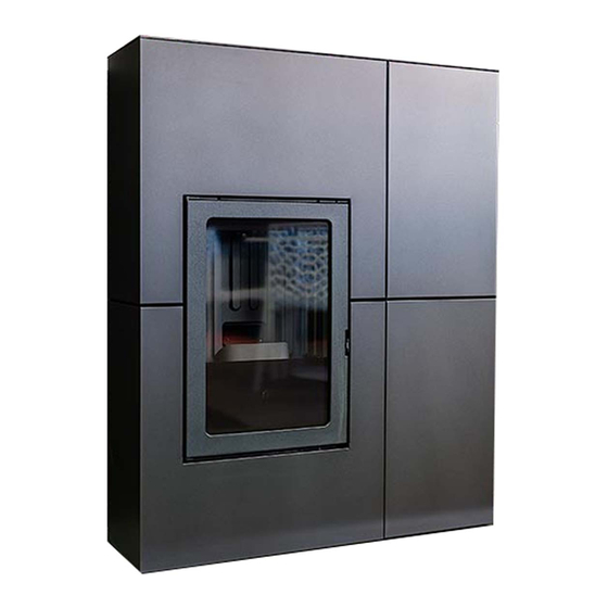
Pellet boiler stove
Hide thumbs
1
2
3
4
5
6
7
8
9
10
11
12
13
14
15
16
17
18
19
20
21
22
23
24
25
26
27
28
29
30
31
32
33
34
35
36
37
38
39
40
41
42
43
44
45
46
47
48
49
50
51
52
53
54
55
56
57
58
59
60
Table Of Contents
61
page
of
61
Go
/
61
Contents
Table of Contents
Troubleshooting
Bookmarks
Table of Contents
Meaning of Symbols
Operating Sequence
Technical Data
Electrical Specifications
Preparation and Unpacking
Installazione
Adjustable Feet
Wall Mounting
Water Circuit Installation
Pressure Gauge
Installation
Flue System
External Air Intake
Checking the Electrical Connections
Steel Cladding
Fan Adjustment
Alarm Status
Pellet Loading
Timer Settings
Date and Time
Language Setting
Daily Maintenance
Weekly Maintenance
Seasonal Maintenance
Troubleshooting
Advertisement
Quick Links
Download this manual
BLADE2 H 18 UP
BLADE2 H 22 UP
PELLET BOILER STOVE
For all updates visit www.edilkamin.com
EN
Installation, use and maintenance
page
2
Table of
Contents
Previous
Page
Next
Page
1
2
3
4
5
Advertisement
Table of Contents
Need help?
Do you have a question about the BLADE2 H 18 UP and is the answer not in the manual?
Ask a question
Questions and answers
Related Manuals for EdilKamin BLADE2 H 18 UP
Stove EdilKamin BRIO User Manual
Wood pellet stove (132 pages)
Stove EdilKamin KIRA H 18 Installation, Use And Maintenance Manual
Pellet boiler stove (52 pages)
Stove EdilKamin Toronto Installation, Use And Maintenance Manual
(28 pages)
Stove EdilKamin Extra Series Installation, Use And Maintenance Manual
(179 pages)
Stove EdilKamin BIG Installation, Use And Maintenance Manual
(63 pages)
Stove EdilKamin BIJOUX Directions For Installation, Use And Maintenance
(249 pages)
Stove EdilKamin BIJOUX Installation, Use And Maintenance Manual
(310 pages)
Stove EdilKamin BLADE2 H 22 UP Installation, Use And Maintenance Manual
Pellet boiler stove (61 pages)
Stove EdilKamin BILD Up Directions For Installation, Use And Maintenance
(64 pages)
Stove EdilKamin Blade2 12 Up Directions For Installation, Use And Maintenance
(72 pages)
Stove EdilKamin Iris Plus Installation & Operation Manual
Pellet fire (16 pages)
Stove EdilKamin LOGO Installation, Use And Maintenance Manual
(25 pages)
Stove EdilKamin Logo Installation, Use And Maintenance Manual
(60 pages)
Stove EdilKamin Alpen Installation, Use And Maintenance Manual
(161 pages)
Stove EdilKamin CHERIE UP H Installation, Use And Maintenance Manual
Pellet boiler stove (60 pages)
Stove EdilKamin SOLEIL Manual
(156 pages)
This manual is also suitable for:
Blade2 h 22 up
Table of Contents
Print
Rename the bookmark
Delete bookmark?
Delete from my manuals?
Login
Sign In
OR
Sign in with Facebook
Sign in with Google
Upload manual
Upload from disk
Upload from URL


Need help?
Do you have a question about the BLADE2 H 18 UP and is the answer not in the manual?
Questions and answers