Advertisement
Quick Links
Advertisement

Related Manuals for EdilKamin MITO IDRO


Summary of Contents for EdilKamin MITO IDRO
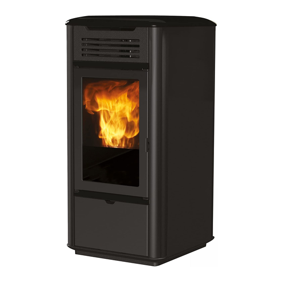
- Page 1 MITO IDRO PELLET BOILER STOVE Installation, use and maintenance page...
- Page 2 Declaration of performance (DoP - EK n° 129): Ref. data tag plate In addition, it is hereby declared that: The wood pellet Boiler-stoves MITO IDRO is in compliance with the requirements of the European directives: - Low voltage directive 2014/35/CE...
- Page 3 Commissioning is required for activation of the Edilkamin The diagrams provided in this manual are for illustration manufacturer warranty. The warranty is only valid in the purposes only: they do not always strictly refer to your country where the product was bought.
- Page 4 DO NOT PLACE LAUNDRY ON Edilkamin nor the retailer are liable for damage resulting from incorrect THE APPLIANCE. DO NOT PLACE DRYING RACKS WITHIN THE SAFETY installation or maintenance. CLEARANCE. Keep flammable fluids Safety risks may be caused by: away from the appliance.
- Page 5 DIMENSIONS MITO IDRO dimensions (cm) Ø 4 cm aria combustione Ø 4 cm aria Combustion air Ø 4 cm aria Ø 4 cm aria combustione Ø 8 cm Ø 40 mm combustione combustione uscita fumi Ø 8 cm Smoke outlet Ø...
- Page 6 Protection on electronic circuit board T2A, 250 Vac, 5x20 Fuse The above data is for guidance only and was measured during certification by a notified body. EDILKAMIN s.p.a. reserves the right to modify the product without notification in the interests of improvement.
- Page 7 DISIMBALLO PREPARAZIONE E DISIMBALLO DISIMBALLO I materiali che compongono l’imballo non sono né Per rimuovere il prodotto dal bancale: tossici né nocivi, pertanto non richiedono particolari • smontare il frontalino inferiore; processi di smaltimento. • svitare le viti di fissaggio al bancale Lo stoccaggio, lo smaltimento o eventualmente il •...
- Page 8 COVERING INSTALLATION 1) CERAMIC VERSION fig. 1 Fig. 1 The stove is delivered (Fig. 1) with the following external components already installed: • aluminium profiles (A) • upper grille (B) • lower panel (C) The pieces indicated below are packaged separately. •...
- Page 9 COVERING INSTALLATION Fig. 4 fig. 4 Attach the upper horizontal ceramic element (F) to the REAR VIEW upper grille (B) using the two M4 knurled bolts and wa- shers provided. fig. 5 Fig. 5 Insert the side ceramic panels (D) into the relevant guides.
- Page 10 COVERING INSTALLATION 2) STEEL VERSION fig. 1 Fig. 1 The stove is delivered (Fig. 1) with the following external components already installed: • metal sides (A) • upper grille (B) • lower panel (C) The pieces indicated below are packaged separately. •...
- Page 11 COVERING INSTALLATION Fig. 4 fig. 4 Attach the upper horizontal ceramic element (F) to the REAR VIEW upper grille (B) using the two M4 knurled bolts and wa- shers provided. fig. 5 Fig. 5 Place the ceramic top (G) above the structure. NB: it the ceramic top does not fit evenly over the structure, use the rubber stoppers (M) and washers provided, inserting them...
- Page 12 The power line must have a suitable cross-section for the boiler power. An inadequate earthing system can cause anomalies for which Edilkamin cannot be held liable. In case of problems with the electrical grid, consult an electrician to evaluate the installation of a sine-wave UPS of at least 800 Va.
- Page 13 INSTALLATION FLUE SYSTEM(Smoke duct, flue THE SMOKE DUCT chimney pot) Further to the general prescriptions for the smoke duct This chapter has been drawn up pursuant to European and flue, the smoke duct: standards EN 13384, EN 1443, EN 1856 and EN 1457. •...
- Page 14 INSTALLATION THE FLUE: AIR INTAKE FOR COMBUSTION Further to the general prescriptions, the flue must In general, we suggest two ways to ensure a proper • only be used to discharge smoke flow of combustion air. Air must come from the outside* •...
- Page 15 L’impianto elettrico deve essere a norma; verificare in particolare l’efficienza del circuito di terra. La non efficienza del circuito di terra provoca mal funzionamento di cui Edilkamin non si potrà far carico. La linea di alimentazione deve essere di sezione adeguata alla potenza dell’apparecchiatura.
- Page 16 This separation is easily carried out using KIT A2 from pending on the type of system installed. Edilkamin. • Fill the system using the filling tap (it is recommended • The presence of a puffer (inertial storage tank) is re- not to exceed a pressure of 1,5 bar).
- Page 17 INSTALLATION • HYDRAULIC CONNECTIONS: HEATING SYSTEM WITH THE THERMO STOVE AS THE ONLY HEAT SOURCE LEGEND Cold Water Water supply Filling/Topping up Filling unit Outlet to system Pump (circulator) Radiators Inlet from system Drain Ø 4 cm aria Temperature Detector combustione Boiler-stove Ø...
- Page 18 INTRODUCTION ABOUT USE FIRST IGNITION (COMMISSIONING) PHASES LOADING THE PELLETS INTO THE TANK. • Make sure you have read and understood this To access the tank, open the lid. manual. • Remove all flammable materials from the appliance When the boiler stove is hot, DO NOT (manuals, labels, etc.).
- Page 19 INTRODUCTION ABOUT USE CONTROL PANEL (P) located beneath the pellet loading door, see previous page DISPLAY INDICATIONS ON/OFF key this also serves to confirm/exit Shut-off phase in progress, duration ap- prox. 10 minutes while the pump continues to work until the set shut- Selection key: access to regulation menu off temperature is reached (usually 40°C)
- Page 20 INTRODUCTION ABOUT USE IGNITION ECONOMY FUNCTION Function suitable for boilers installed in small-scale sys- With the boiler-stove in stand-by mode, (after having tems, or whenever minimum power operation causes ex- checked cessive heating. that the chamber is clean), press the key , and the This function, managed automatically, allows for switch- ignition procedure will start.
- Page 21 INTRODUCTION ABOUT USE SETTING: CLOCK AND WEEKLY PRO- • Pr 1: This is programme no. 1; this is for setting the GRAMMING 1st ignition timetable, the 1st shut-off timetable and the Press the key SET for 2”: this takes you into the program- days on which to apply the timetable Pr 1.
- Page 22 PUMP PUMP SPECIFICATIONS...
- Page 23 PUMP: INSTALLATION AND OPERATING INSTRUCTIONS CONTROL MODES AND FUNCTIONS Variable differential pressure Δp-v (I, II, III) Recommended for two-pipe heating systems with radiators to reduce the flow noise at thermostatic valves. The pump reduces the delivery head to half in the case of decreasing volume flow in the pipe network.
- Page 24 PUMP: INSTALLATION AND OPERATING INSTRUCTIONS VENTING Activate the pump venting function via the operating button: press and hold for 3 seconds, then release. •The pump venting function is initiated and lasts 10 minutes. •The top and bottom LED rows flash in turn at 1 second intervals.
- Page 25 PUMP: INSTALLATION AND OPERATING INSTRUCTIONS Press the BUTTON LED display Control mode Pump curve Constant speed Constant speed Variable differential pressure Δp-v Variable differential pressure Δp-v Variable differential pressure Δp-v Constant differential pressure Δp-c Constant differential pressure Δp-c Constant differential pressure Δp-c Constant speed Pressing the button for the 9th time returns to the factory setting (constant speed / pump...
- Page 26 PUMP: INSTALLATION AND OPERATING INSTRUCTIONS Lock/unlock the button To activate the key lock, press and hold the operating button for 8 seconds until the LEDs for the selected setting briefly flash, then release. •LEDs flash constantly at 1-second intervals. •The key lock is activated: pump settings can no longer be changed.
- Page 27 PUMP: INSTALLATION AND OPERATING INSTRUCTIONS FAULT SIGNALS • The fault signal LED indicates a fault. • The pump switches off (depending on the fault) and attempts a cyclical restart. FAULTS CAUSES REMEDY Blocking Rotor blocked Activate manual restart or Lights up red contact customer service Contacting/ winding Winding defective...
- Page 28 MAINTENANCE Before performing any maintenance, disconnect the appliance from the mains. Regular maintenance is required for the boiler-stove to function correctly. Any problems resulting from lack of maintenance will immediately void the warranty. N.B. - Any unauthorised modification is forbidden - Use spare parts recommended by the manufacturer - The use of counterfeit parts results in the guarantee becoming null and void...
- Page 29 You should clean the chimney system at least once a Using non-original spare parts may damage the year (check local regulations for details). appliance and relieves Edilkamin of all liability for damage that may arise from doing this. If you fail to regularly clean and inspect the system, Do not make unauthorised modifications.
- Page 30 TROUBLESHOOTING In the event of problems the boiler-stove stops automatically and runs the shutdown pro- cess and the display shows text regarding the motivation of the shutdown (see the various alarms below). Never pull the plug during shutdown on account of malfunction. To start the boiler-stove up again after a shutdown, let the shutdown procedure end (10 minutes marked by a beep) tand then press the button...
- Page 31 TROUBLESHOOTING 7) Signalling: H7 over heated fumes (turns off due to exceeding maximum smoke temperature). Problem: Switches off because of overheated fumes. Over heated fumes may depend on: type of pellets, anomalous fume extraction, blocked channel, incorrect installation, gear motor drift, lack of air vents in the room. 8) Signalling: H8 H2O temp alarm (this occurs if the water temperature sensor reads a temperature above 90°C)
- Page 32 *941357-GB* w w w . e d i l k a m i n . c o m cod. 941357-GB 1.17/A...
Need help?
Do you have a question about the MITO IDRO and is the answer not in the manual?
Questions and answers