Sign In
Upload
Download
Table of Contents
Contents
Add to my manuals
Delete from my manuals
Share
URL of this page:
HTML Link:
Bookmark this page
Add
Manual will be automatically added to "My Manuals"
Print this page
×
Bookmark added
×
Added to my manuals
Manuals
Brands
Sames Manuals
Paint Sprayer
Mach-Jet
User manual
Sames Mach-Jet User Manual
Hide thumbs
1
2
Table Of Contents
3
4
5
6
7
8
9
10
11
12
13
14
15
16
17
18
19
20
21
22
23
24
25
26
27
28
29
30
31
32
33
34
35
36
37
38
39
40
41
42
43
44
45
46
47
page
of
47
Go
/
47
Contents
Table of Contents
Troubleshooting
Bookmarks
Table of Contents
Table of Contents
Regulations, Safety Regulations and Guarantee
Regulations
Safety Regulations
Guarantee
Presentation
Characteristics
General Characteristics
Compressed Air Quality
Operation
Back of "CRN 457" Control Module
Module Connections
Module Identification Plate
Description of Spray Gun and Control Module
Functions Available from Spray Gun
Functions Available from Control Module
Summary
Use of the Different Control Module Menus
CRN 457 Initialisation Screen
Start-Up Screen
Manual Unit Without PLC Connection
Manual Unit with PLC Connection
Cleaning Screen (Only with a Carriage)
Standby Screen (Only with a Communication with a PLC)
Main Screen "A
Screen "B
Screen "C
Screen "D
Fault List
Screen "E
Screen "F
Screen "G
Screen "H
Maintenance
Deflector and Nozzle
Disassembly
Assembly
Vertical Powder Pipe
Powder Elbow and Horizontal Pipe
Disassembly
Assembly
Handle Assembly
Disassembly
Assembly
Trigger
Disassembly
Assembly
Hand-Rest
Disassembly
Reassembly
Gun
Disassembly
Assembly
Cable Assembly
Disassembly
Assembly
Cleaning/Maintenance
Troubleshooting
Spare Parts List
Mach-Jet Spray Gun - Ref.: 1524463
Gun Assembly - Ref.: 1524464
Handle Assembly - Ref.: 1525908
Vertical Powder Pipe Assembly - Ref.: 1525793
Nozzles
Fan Spray Nozzle
Round Spray Nozzle
Extended Nozzles
Equipment
FM Approved" Configurations
Advertisement
Quick Links
1
Troubleshooting
Download this manual
User manual
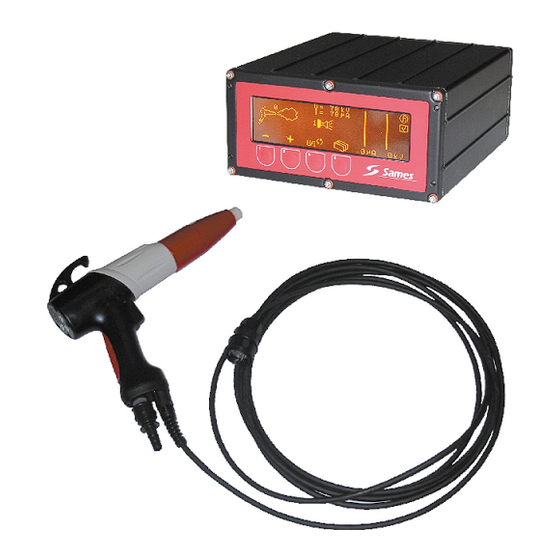
Mach-Jet Spray Gun
and
CRN 457 control module
SAMES Technologies. 13 Chemin de Malacher 38243 Meylan Cedex
Tel. 33 (0)4 76 41 60 60 - Fax. 33 (0)4 76 41 60 90 - www.sames.com
Index revision : H
1
6336
Table of
Contents
Previous
Page
Next
Page
1
2
3
4
5
Advertisement
Table of Contents
Need help?
Do you have a question about the Mach-Jet and is the answer not in the manual?
Ask a question
Questions and answers
Related Manuals for Sames Mach-Jet
Paint Sprayer Sames inocoat Inogun A Instruction Manual
(87 pages)
Paint Sprayer Sames Inocart VT Instruction Manual
Cart for powder gun (67 pages)
Paint Sprayer Sames Inocoat Inogun M Instruction Manual
Powder spray gun (69 pages)
Paint Sprayer Sames NANOGUN-MV LR User Manual
(64 pages)
This manual is also suitable for:
Crn 457
Table of Contents
Save PDF
Print
Rename the bookmark
Delete bookmark?
Delete from my manuals?
Login
Sign In
OR
Sign in with Facebook
Sign in with Google
Upload manual
Upload from disk
Upload from URL


Need help?
Do you have a question about the Mach-Jet and is the answer not in the manual?
Questions and answers