Table of Contents
Advertisement
Quick Links
Advertisement
Table of Contents

Related Manuals for Clipper CM 501 HONDA


Summary of Contents for Clipper CM 501 HONDA
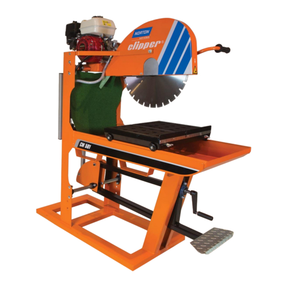
- Page 1 CM 501 HONDA OPERATING INSTRUCTIONS Translation of the original instructions...
- Page 2 VERS. 2017.06.21 CM 501 TH_MAN_EN...
- Page 3 VERS. 2017.06.21 CM 501 TH_MAN_EN Declaration of conformity The undersigned manufacturer: SAINT - GOBAIN ABRASIVES S.A. 190, BD J.F. KENNEDY L- 4930 BASCHARAGE Declares that this product: CM 501 3.60 P 70184627020 Masonry Saws: Code: is in conformity with the following Directives: ...
- Page 4 VERS. 2017.06.21 CM 501 TH_MAN_EN...
-
Page 5: Table Of Contents
VERS. 2017.06.21 CM 501 TH_MAN_EN CM501 HONDA OPERATING INSTRUCTIONS AND SPARE PARTS LIST 1 BASIC SAFETY INSTRUCTIONS 1.1 Symbols 1.2 Machine plate 1.3 Safety instructions for particular operating phases 2 MACHINE DESCRIPTION 2.1 Short description 2.2 Purpose of use 2.3 Layout 2.4 Technical Data 2.5 Statement regarding the vibration emission 2.6 Statement regarding noise emission... -
Page 6: Basic Safety Instructions
VERS. 2017.06.21 CM 501 TH_MAN_EN 1 BASIC SAFETY INSTRUCTIONS The CM501 is exclusively designed for the cutting of construction products mainly on construction sites. Uses other than the manufacturer's instructions shall be considered as contravening the regulations. The manufacturer shall not be held responsible for any resulting damage. Any risk shall be borne entirely by the user. -
Page 7: Machine Plate
VERS. 2017.06.21 CM 501 TH_MAN_EN 1.2 Machine plate Important data can be found on the following plate located on the machine: Maximum blade diameter Weight Year of production Machine Code Machine Model Bore diameter Machine type Power Safety standard Blade speed Serial number 1.3 Safety instructions for particular operating phases Before commencing work... -
Page 8: Machine Description
VERS. 2017.06.21 CM 501 TH_MAN_EN 2 MACHINE DESCRIPTION Any modification, which could lead to a change in the original characteristics of the machine, may be done only by Saint-Gobain Abrasives who shall confirm that the machine is still in conformity with the safety regulations. - Page 9 VERS. 2017.06.21 CM 501 TH_MAN_EN Frame (1) The jig-welded, reinforced and all-steel construction, diagonally braced to ensure perfect rigidity. The frame includes a large capacity, sloping water tray with drain plug. Frame has built-in fork lift brackets (7) for easy transportation. The large base ensures stability while used. Cutting head (2) Jig-welded, steel console equipped with pivot bar, which is fixed to frame uprights.
-
Page 10: Technical Data
VERS. 2017.06.21 CM 501 TH_MAN_EN 2.4 Technical Data Motor Honda GX200 4.8kW (6.5 HP) Fuel Automotive unleaded gasoline Honda 4-Stroke, or equivalent high detergent, premium quality motor oil certified to meet or exceed U.S. automobile manufacturer’s requirement for service classification SG, SF. Motor oil (SG, SF designated on the oil container). -
Page 11: Statement Regarding The Vibration Emission
Measured value of vibration Uncertainty K Tool used Model / code emission at m/s Model / code CM 501 3.60 Clipper ZDH500 <2.5 diamond blade 70184627020 The vibration value is lower and does not exceed 2.5 m/s². Values determined using the procedure described in the standard EN 12418. -
Page 12: Statement Regarding Noise Emission
VERS. 2017.06.21 CM 501 TH_MAN_EN 2.6 Statement regarding noise emission Declared value of noise emission following EN ISO 11201 and NF EN ISO 3744. Machine Sound Uncertainty K Sound power Uncertainty K Model / code Pressure level (Sound level (Sound power level Pressure level EN ISO 11201 NF EN ISO 3744... -
Page 13: Assembly And Commissioning
VERS. 2017.06.21 CM 501 TH_MAN_EN 3 ASSEMBLY AND COMMISSIONING The machine is delivered fully equipped and assembled (although without diamond blade) and is ready for operation after connection to the appropriate power supply. 3.1 Tool assembly Only NORTON blades with a maximum diameter of 500 mm can be used with the CM501. All tools used must be selected with regard to their maximum permitted cutting speed for the machine’s maximum permitted rotation speed. -
Page 14: Starting The Machine
VERS. 2017.06.21 CM 501 TH_MAN_EN 3.3 Starting the machine Turn the fuel valve to the ON position. Move the choke lever to the CLOSED position. NOTE: do not use the choke if the engine is warm or the air temperature is high. Move the throttle control lever slightly to the Put the engine switch on ON, and make sure left. -
Page 15: Transport And Storing
VERS. 2017.06.21 CM 501 TH_MAN_EN 4 TRANSPORT AND STORING 4.1 Securing for transport Before transporting or lifting the machine, always remove the blade and the conveyor cart and empty the water pan. 4.2 Transport procedure If you transport the machine using a fork-lift truck, you have to use EXCLUSIVELY the two fork lift brackets under the water pan. -
Page 16: Operating The Machine
VERS. 2017.06.21 CM 501 TH_MAN_EN 5 OPERATING THE MACHINE 5.1 Site of work 5.1.1 Siting the machine Remove from the site anything, which might hinder the working procedure! Make sure the site is sufficiently well lit! Observe manufacturer's conditions for connecting to power supplies! ... - Page 17 VERS. 2017.06.21 CM 501 TH_MAN_EN 5.2.2 Multiple step cutting Multiple step cutting consists of moving the conveyor cart with the material to be cut back and forward under the rotating blade, Place the material to be cut on the conveyor cart firmly against the guide-a-cut and the backstop, keeping the hands well away from the blade.
-
Page 18: Maintenance And Servicing
VERS. 2017.06.21 CM 501 TH_MAN_EN 6 MAINTENANCE AND SERVICING 6.1 Maintenance of the machine To ensure a long-term quality from the cutting with the CM501, please follow the maintenance plan below: Whole machine Visual control (general aspect, watertightness) Clean Flange and blade fixing devices Clean Belts tension Check and adjust... - Page 19 VERS. 2017.06.21 CM 501 TH_MAN_EN Regular service period Perform at every indicated month or operating hour interval, whichever comes first Check level Engine oil Change Check level Reduction gear oil Change Check Air cleaner filter Clean Fuel strainer cup Clean Spark plug Check-Clean...
- Page 20 VERS. 2017.06.21 CM 501 TH_MAN_EN Air cleaner The CM501 has a dual type filter. To service the air cleaner filter, follow these instructions: Remove the nut, air cleaner cover and wing nut. Remove the pre air cleaner elements and separate them.
- Page 21 VERS. 2017.06.21 CM 501 TH_MAN_EN Spark plug To service the spark plug, follow these instructions: Visually inspect spark plug. Discard the plug if the insulator is cracked or chipped. Remove carbon or other deposits with a stiff wire brush. ...
-
Page 22: Faults: Causes And Cures
VERS. 2017.06.21 CM 501 TH_MAN_EN 7 FAULTS: CAUSES AND CURES Fault-finding procedures Should any fault occur during the use of the machine, turn it off, and isolate it from the electrical supply. Any works dealing with the electrical system or supply of the machine can only be carried out by a qualified electrician. -
Page 23: Customer Service
VERS. 2017.06.21 CM 501 TH_MAN_EN 7.3 Customer service When ordering spare parts, please mention: The serial number (a letter and 6 digits). The code of the part. The exact denomination. The number of parts required. The delivery address. - Page 24 VERS. 2017.06.21 CM 501 TH_MAN_EN Guarantee can be claimed and technical support obtained from your local distributor where machines, spare parts and consumables can be ordered as well:...
Need help?
Do you have a question about the CM 501 HONDA and is the answer not in the manual?
Questions and answers