Emerson Bettis EHO Installation, Operation And Maintenance Manual
Spring-return actuator
Hide thumbs
Also See for Bettis EHO:
- Installation and operation manual (43 pages) ,
- Installation and operation manual (51 pages)

Related Manuals for Emerson Bettis EHO


Summary of Contents for Emerson Bettis EHO
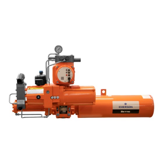
- Page 1 Installation, Operation and Maintenance Manual VA001-507-32 Rev. 1 December 2022 Bettis EHO (Electro-Hydraulic Operated) ™ Spring-Return Actuator...
- Page 2 Notes Installation, Operation and Maintenance Manual December 2022 VA001-507-32 Rev. 1 This page intentionally left blank...
-
Page 3: Table Of Contents
Installation, Operation and Maintenance Manual Table of Contents VA001-507-32 Rev. 1 December 2022 Table of Contents Section 1: Introduction Scope ......................1 General Information ..................1 Safety Information ..................1 Abbreviation Definitions ................2 Section 2: Installation Preparation ....................3 Valve Preparation .................. - Page 4 Table of Contents Installation, Operation and Maintenance Manual December 2022 VA001-507-32 Rev. 1 Section 5: Operation Hydraulic Power System ................30 Fluid Reservoir..................... 30 Main Components and Options ..............30 Functional Description ................32 Section 6: Pushbutton Module (PBM) Selector Knob and Control Pushbuttons ............35 Section 7: Troubleshooting Troubleshooting ....................
-
Page 5: Section 1: Introduction
This manual is offered as a guide to be used along with locally approved and safe practices to install, operate, service and maintain the Bettis EHO Actuator. Carefully follow the instructions in this manual and make sure you install the actuator correctly and according to your requirements. -
Page 6: Abbreviation Definitions
CAUTION Identifies precautions, the user must take to avoid personal injury or equipment damage. NOTE: Highlights information critical to the user’s understanding of the Bettis EHO valve actuator installation or operation. Abbreviation Definitions Abbreviations used in this manual and their definitions are listed in the table below: Table 1. -
Page 7: Section 2: Installation
For storage procedures exceeding one year, consult Bettis for further recommendations. As shipped from the factory, the Bettis EHO actuator is an inherently weatherproof unit, providing that all compartment covers and cable entry plugs remain intact. The actuator should be immediately stored in a clean, dry warehouse, free from vibration and rapid temperature changes, until it can be installed and energized. -
Page 8: Valve Preparation
Section 2: Installation Installation, Operation and Maintenance Manual December 2022 VA001-507-32 Rev. 1 Valve Preparation 2.2.1 Remove Valve Gearing if so equipped. 2.2.2 If valve is equipped with stops, remove valve stem extension housing. Examine the valve stops to ensure no foreign material is present that would restrict normal travel of the valve. -
Page 9: Lifting The Eho Actuator
December 2022 Lifting the EHO Actuator NOTE: All Bettis EHO G-Series or E-Series Considerations When handling any EHO, G-Series or E-Series actuator, be aware of tubing, accessories, handpump, accumulators, pushbutton module, and control enclosures. Straps and chains can become entangled and cause damage to these components. Never use chains on the spring cartridge as it may warp and cause the actuator not to function correctly or may cause personal injury. - Page 10 Section 2: Installation Installation, Operation and Maintenance Manual December 2022 VA001-507-32 Rev. 1 2.4.1.2 Horizontal Pipeline Horizontal Stem The small G-Series and all E-Series actuators mounting on a horizontal pipeline with a horizontal valve stem should be supported on the ends of the drive module.
- Page 11 Installation, Operation and Maintenance Manual Section 2: Installation VA001-507-32 Rev. 1 December 2022 2.4.2.2 Horizontal Pipeline Vertical Stem The G3-Series actuator mounting on a horizontal pipeline with a horizontal valve stem should be supported on the ends of the drive module.
- Page 12 Section 2: Installation Installation, Operation and Maintenance Manual December 2022 VA001-507-32 Rev. 1 2.4.3.2 Horizontal Pipeline Horizontal Stem The G4 – G7 Series actuators mounting on a horizontal pipeline with a vertical valve stem should be supported using the lift lugs attached to the drive module.
- Page 13 Mounting the Actuator in a Vertical Orientation on a Horizontal Stem When mounting a Bettis EHO Actuator in a vertical orientation, the spring module must be positioned up. The actuator may be supported by using two straps in the configuration shown in Figure 6.
-
Page 14: Installing The Eho Actuator On The Valve
Section 2: Installation Installation, Operation and Maintenance Manual December 2022 VA001-507-32 Rev. 1 Installing the EHO Actuator on the Valve The actuator will be bolt-mounted directly to a bracket or adaptor that will be bolted securely to the mounting flange top works of the valve. 2.5.1 Check to see that the dimensions of the bracket or adaptor are suitable for use with the valve mounting flange and stem. -
Page 15: Setting The Stroke Limit Stops
Installation, Operation and Maintenance Manual Section 2: Installation VA001-507-32 Rev. 1 December 2022 Setting the Stroke Limit Stops 2.6.1 The Bettis G or E-Series Actuator is provided with bi-directional travel stops allowing 80° to 100° total travel (+/- 5° adjustment at each end of the 90° stroke). 2.6.2 Actuators are shipped from the factory with the travel stops adjusted for approximately 90°... -
Page 16: Hydraulic Fluid
Accumulator (Optional) 2.8.1 Introduction The Bettis EHO Actuator may be equipped with an accumulator to enable manual operation of the actuator if there is a loss of electrical power. Accumulators always have the nitrogen pressure drained for shipping. When using this procedure, refer to the Bettis EHO Actuator General Arrangement drawing and Hydraulic Schematic for the unit being worked on, (schematics shown in this document are for illustration purposes only). - Page 17 Installation, Operation and Maintenance Manual Section 2: Installation VA001-507-32 Rev. 1 December 2022 2.8.2 Accumulator Pre-charge Locate Isolation Valve (25) (Nitrogen Blow Down and Fill) for the Customer Nitrogen Fill Connection, called out on the General Arrangement Drawing and Hydraulic Schematic (see illustration below). Close the Isolation Valve (25) (Nitrogen Blow Down and Fill) and remove the pipe plug from the adaptor.
- Page 18 Section 2: Installation Installation, Operation and Maintenance Manual December 2022 VA001-507-32 Rev. 1 Figure 7 Typical EHO Optional Accumulator System TO MANIFOLD POWER PORT TO CYLINDER Table 3. Part Number Part Name Reservoir Accumulator Nitrogen Relief Valve 3-way Isolation Valve Isolation Valve (Accumulator Drain) Isolation Valve (Nitrogen Blow Down and Fill) Nitrogen Pressure Gauge...
- Page 19 Installation, Operation and Maintenance Manual Section 2: Installation VA001-507-32 Rev. 1 December 2022 2.8.3 Pre-charge Verification Check the nitrogen pre-charge in the accumulator periodically to ensure the accumulator is at full potential. Follow the steps below and record final readings for reference. Shut off the hydraulic power supply to the accumulator.
- Page 20 Section 2: Installation Installation, Operation and Maintenance Manual December 2022 VA001-507-32 Rev. 1 2.8.5 Nitrogen Pre-charge Maintenance Record Serial Number: _____________________________ Tag Number: _______________________________ Initial Final Nitrogen Date Signed Pre-charge Requirement Pre-charge Leak Test Installation...
-
Page 21: Section 3: Electrical Connections
Installation, Operation and Maintenance Manual Section 3: Electrical Connections VA001-507-32 Rev. 1 December 2022 Section 3: Electrical Connections Remove Separate Terminal Chamber (STC) Cover WARNING Always verify electrical power is disconnected before removing the STC cover. 3.1.1 Remove cover with a strap wrench, drift, or pinch bar by rotating the cover counterclockwise. -
Page 22: Sealing Cable/Conduit Entries
Section 3: Electrical Connections Installation, Operation and Maintenance Manual December 2022 VA001-507-32 Rev. 1 Sealing Cable/Conduit Entries Seal the cable and conduit entries in accordance with the National Electric Code or your country standard and applicable local codes. All conduit entries should be sealed against the site environment. -
Page 23: Separate Terminal Chamber (Stc) Connections
Installation, Operation and Maintenance Manual Section 3: Electrical Connections VA001-507-32 Rev. 1 December 2022 Separate Terminal Chamber (STC) Connections 3.4.1 Connect the main power supply cables, including an Earth/Ground (refer to the job specific General Arrangement Drawing). 3.4.2 Use the barrier strip clamp screws to connect the control wiring (refer to the job specific General Arrangement Drawing). -
Page 24: Discrete Controlled Inputs Connection
INTERPRET DIMENSIONS AND TOLERANCE PER EWD-A2SA0-30 t bears, is the property of Emerson and must be held in strict confidence and properly safeguarded by the recipient at all times. It may not be copied or reproduced, or provided or ASME Y14.5 thorization of Emerson and any authorized copy or reproduction must include this legend. -
Page 25: Section 4: Set-Up/Start-Up Procedure
( ) correspond to components labeled on the schematic diagram. Information in (( )) is descriptive. When the Bettis EHO is delivered to the job site, it has been both pressure and function tested. The oil reservoir was filled to operation level when it shipped from factory. -
Page 26: Initial Check Of The Unit
Section 4: Set-up/Start-up Procedure Installation, Operation and Maintenance Manual December 2022 VA001-507-32 Rev. 1 4.1.2 Material and Equipment for Start-up and Set-up To complete this procedure, you will also need the following materials and equipment: Table 4. Required Material and Equipment Required Material and Equipment Miscellaneous fittings, adaptors and Hand Tools: complete complement of open end ((SAE and metric)) wrenches, screw drivers Philips and flat blade and a set of hex wrenches... -
Page 27: Handpump
Installation, Operation and Maintenance Manual Section 4: Set-up/Start-up Procedure VA001-507-32 Rev. 1 December 2022 Handpump 4.4.1 Check the Reservoir (4) to see the hydraulic fluid is at the proper level. 4.4.2 Close Handpump Isolation Valve (8). NOTE: Handpump Isolation Valve (8) Remove the Protective Cap. -
Page 28: Check Rotation
Section 4: Set-up/Start-up Procedure Installation, Operation and Maintenance Manual December 2022 VA001-507-32 Rev. 1 Check Rotation 4.6.1 Turn on the electrical supply to the unit. If an ((optional)) Circuit Breaker Module is supplied, turn the Circuit Breaker to ON. 4.6.2 Turn the LOCAL-OFF-REMOTE selector switch to LOCAL. -
Page 29: Limit Switch Adjustment
Installation, Operation and Maintenance Manual Section 4: Set-up/Start-up Procedure VA001-507-32 Rev. 1 December 2022 4.6.7 Push and release the OPEN/CLOSE PUSHBUTTON to power stroke the actuator. The Electric Motor (2) will start to run driving Hydraulic Pump (3). The Hydraulic Pump (3) draws fluid from Reservoir (4) and pushes it into the Bettis G or E-Series hydraulic cylinder (1). - Page 30 Section 4: Set-up/Start-up Procedure Installation, Operation and Maintenance Manual December 2022 VA001-507-32 Rev. 1 4.7.3 Fail-Safe Close Limit Switch Adjustment 4.7.3.1 The Open and Close Limit Switches, shown in Figure 16, are operated by targets mounted in a plastic disk that rotates with the actuator stroke.
- Page 31 Installation, Operation and Maintenance Manual Section 4: Set-up/Start-up Procedure VA001-507-32 Rev. 1 December 2022 4.7.3.7 Push down and slide Target for OPEN LS-1 counterclockwise until it is off the switch in the counterclockwise direction. 4.7.3.8 Now, push down and slide the Target for OPEN LS-1 clockwise until the CLOSE light just goes out.
-
Page 32: Function Test
Section 4: Set-up/Start-up Procedure Installation, Operation and Maintenance Manual December 2022 VA001-507-32 Rev. 1 Function Test NOTE: If the EHO Actuator is supplied with optional ESD before operating a motor powered stroke, a customer supplied ESD signal must be present and Solenoid Valve (17) energized. 4.8.1 Ensure the Handpump Isolation Valve (8) is open and check to see Manual Bypass Valve (Lockable) (19) is closed. -
Page 33: Other Options
Other options may have been supplied with this order. Refer to supplemental start-up procedures supplied with these options for start-up and test. The functional test of the Electro-Hydraulic Actuator is now complete. The Bettis EHO Actuator is now operational and ready for service. Set-up/Start-up Procedure... -
Page 34: Section 5: Operation
Section 5: Operation After initial start-up and commissioning procedures have been accomplished, the Bettis EHO Actuator provides a simple self-contained means of operation for a quarter-turn valve. In case of a power failure, the actuator can be operated by the use of the supplied handpump. - Page 35 Installation, Operation and Maintenance Manual Section 5: Operation VA001-507-32 Rev. 1 December 2022 — (10) Relief valve: A pressure relief valve is provided to protect the actuator and control system from over-pressurization caused by the pump or thermal expansion of the hydraulic fluid. This valve is factory set, do not adjust.
-
Page 36: Functional Description
Section 5: Operation Installation, Operation and Maintenance Manual December 2022 VA001-507-32 Rev. 1 Functional Description The following is a functional description of the Bettis Electro-Hydraulic Actuator and a brief explanation of the main components. Throughout this explanation, numbers which appear in [ ] correspond to components labeled on the wiring diagram. - Page 37 Installation, Operation and Maintenance Manual Section 5: Operation VA001-507-32 Rev. 1 December 2022 5.4.6 Manual Handpump Power Stroke Close handpump isolation valve (8). Stroke handpump (13) until the OPEN/CLOSE stroke is complete. Open isolation valve (8) when the handpumping is complete. NOTE: If equipped with ESD, Do Not open Isolation Valve (8) before the customer supplied ESD Signal is present.
-
Page 38: Section 6: Pushbutton Module (Pbm)
Section 6: Pushbutton Module (PBM) Installation, Operation and Maintenance Manual December 2022 VA001-507-32 Rev. 1 Section 6: Pushbutton Module (PBM) The Pushbutton Module consists of the following as shown in Figure 17: • Two Pilot Lights: OPEN and CLOSE • Three Pushbuttons: OPEN, CLOSE, and STOP •... -
Page 39: Selector Knob And Control Pushbuttons
Installation, Operation and Maintenance Manual Section 6: Pushbutton Module (PBM) VA001-507-32 Rev. 1 December 2022 Selector Knob and Control Pushbuttons The selector knob provides the choice of Local/Off/Remote operation. The control pushbuttons perform normal Open/Stop/Close function in the local control mode. Table 5. -
Page 40: Section 7: Troubleshooting
Section 7: Troubleshooting Installation, Operation and Maintenance Manual December 2022 VA001-507-32 Rev. 1 Section 7: Troubleshooting WARNING To prevent personal injury, the actuator must be in spring-return, Fail-Safe Position and all hydraulic pressure drained, including an optional accumulator, before opening any tube lines or attempting replacement operations below. -
Page 41: Hazardous Area Classification And Sil Certification
Installation, Operation and Maintenance Manual Section 8: Hazardous Area Classification VA001-507-32 Rev. 1 December 2022 Section 8: Hazardous Area Classification and SIL Certification — CSA, Canadian Standard Association Certification Class I, Division I, Groups, C and D. Group B configuration upon request —... -
Page 42: Section 9: Weights And Dimensions
Section 9: Weights and Dimensions Installation, Operation and Maintenance Manual December 2022 VA001-507-32 Rev. 1 Section 9: Weights and Dimensions EHO Standard Spring-Return CENTERLINE BETTIS G-SERIES ACTUATOR THERMAL COMPENSATING ACCUMULATOR ISOLATION VALVE, BY-PASS GAUGE CENTERLINE HYDRAULIC MANIFOLD CENTERLINE HANDPUMP LOCAL PUSHBUTTON MODULE ELECTRIC MOTOR POWER PACK SUPPORT POINT (DO NOT LIFT FROM THIS POINT) -
Page 43: Section 10: Maintenance
Installation, Operation and Maintenance Manual Section 10: Maintenance VA001-507-32 Rev. 1 December 2022 Section 10: Maintenance 10.1 Storage Procedures The actuator should be immediately stored in a clean, dry warehouse, free from vibration and rapid temperatures changes, until it can be installed and energized. If the actuator must be stored outside, it should be stored off of the ground at an elevation sufficient to prevent it from being immersed in water or buried in snow, and covered to prevent damage from site debris. -
Page 44: Lubrication Requirements
Check the breather on the hydraulic reservoir Qualified service personnel are available upon request for problems, which our customers do not wish to handle. If the requirement should arise please feel free to contact: Emerson Actuation Technologies, Inc. 19200 Northwest Freeway... - Page 45 Installation, Operation and Maintenance Manual Notes VA001-507-32 Rev. 1 December 2022 This page intentionally left blank...
- Page 46 Tianjin 301700 Holland Fasor 6 P. R. China Székesfehérvár 8000 The Emerson logo is a trademark and service mark of Emerson Electric Co. T +86 22 8212 3300 Hungary Bettis is a mark of one of the Emerson family of companies.
Need help?
Do you have a question about the Bettis EHO and is the answer not in the manual?
Questions and answers