Table of Contents
Advertisement
Advertisement
Table of Contents

Subscribe to Our Youtube Channel
Related Manuals for Dräger Polytron FX


Summary of Contents for Dräger Polytron FX
- Page 1 Polytron FX Operating Manual...
-
Page 2: For Your Safety
For Your Safety For Your Safety Strictly follow the assembly and installation instructions The instrument must be calibrated at intervals recommended in the operating manual or more frequently according to specific use and applications. Do not calibrate the instrument in the presence of an operating radio transmitter. -
Page 3: Table Of Contents
1.2.2 Stainless Steel Version ................5 2 Operation ......................6 2.1 Installation ......................6 2.2 Replacing the Sensor ..................7 2.3 Change Gas Category of Polytron FX IR ............8 3 Menu ........................9 3.1 Menu Navigation ....................9 3.2 Changing Parameter Values/Status ..............9 3.3 Exiting the Menu .................... - Page 4 Contents 5 Sensor Principle ....................16 5.1 Operating Principle for DraegerSensor PR and LC ......... 16 5.2 Contaminating Gases for DraegerSensor PR and LC ......16 5.3 Operating Principle for DraegerSensor IR ..........17 6 Technical Information ..................18 6.1 Approvals ......................18 6.1.1 Aluminum Version ................
-
Page 5: Introduction
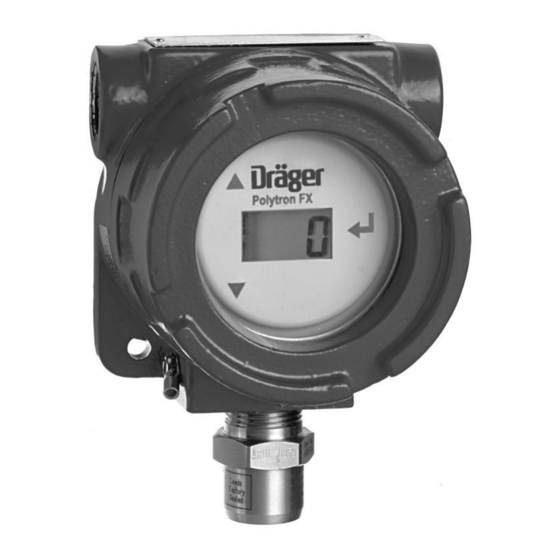
Design Introduction Intended Use The Polytron FX is an explosion-proof transmitter for the detection of combustible gases and vapors in ambient air. The transmitter is designed to be installed in permanent locations and is approved for use in hazardous, classified areas (See Section 6.1, Approvals). -
Page 6: Stainless Steel Version
Intended Use Design 1.2.2 Stainless Steel Version The Polytron FX transmitter is housed in an enclosure with 3/4” NPT threaded ports located at the 12 and 6 o’clock positions. Figure 1a: Polytron FX and Polytron FX IR, stainless steel version... -
Page 7: Operation
Polytron FX rests with the end user; if in doubt about placement, consult with Draeger application engineers. Polytron FX is a three-wire device powered by 16 to 30 V DC. Wiring terminals are located on the back of the PCB; pull out the bezel, by grasping the notches on either side of the display with your fingers and pulling up (Figure 2). -
Page 8: Replacing The Sensor
Installing the Sensor Wiring to and from controllers/power supplies must be run through sealed conduit to maintain the explosion-proof status. If only one of the threaded inlet ports is used for external wiring, the other must be sealed with the blanking plug included with the unit (Figure 4). -
Page 9: Change Gas Category Of Polytron Fx Ir
Plug wires into socket on Main PCB Housing Threaded Port Sensor Wires DraegerSensor IR DraegerSensor PR or LC Figure 5: Replacing the sensor Change Gas Category of Polytron FX IR See manual 9023843. This has to be done at the DraegerSensor IR. -
Page 10: Menu
Menu Menu Navigation Changing Parameter Values/Status Exiting the Menu Menu In the standard operating mode, the Gas Concentration of the target gas will be displayed. To access the software menu, tap the magnetic wand once against the glass viewport above the Down arrow. The display shows the first menu item, Adj Zero. -
Page 11: Exiting The Menu
This field is read-only, and cannot be modified by the operator. 3.4.2 Password The use of a password is optional with the Polytron FX. A password consists of a 3-digit number from 000 to 999; a value of 000 disables password protection and allows anyone to access the software interface. -
Page 12: Span Adj
50 once the sensor reading has stabilized. See Section 4.1.1, Calibration Procedure, for details. 3.4.5 FSD Adj The Full Scale Deflection is fixed at 100% LEL for the Polytron FX and Polytron FX IR or 10% LEL for the Polytron FX LC. 3.4.6 A1 Adj This menu item is not active for the Polytron FX. -
Page 13: Output And Display Variations
Output and Display Variations Output and Display Variations The following table shows the status of the 4 to 20 mA output, and the LCD display for various conditions. Condition Analog Output LCD Display Warming-up actual signal actual signal After warm-up actual signal actual signal After power outage... -
Page 14: Maintenance
If the zero signal has drifted significantly, or a calibration fails: calibrate the DraegerSensor IR first (see manual P/N 9023843), then continue with the calibration procedure for Polytron FX. 4.1.1.1 Zero Calibration • Attach the pressure regulator to the nitrogen (N2) or Zero Air calibration gas cylinder. -
Page 15: Span Calibration
Calibration • Connect the tubing to the barbed fitting of the sensor. • IMPORTANT: Turn the gas on and allow to flow for at least one minute before proceeding. • Scroll through software menu to Zero Adj and tap Enter. The current zero value will be displayed. -
Page 16: Error Messages
Error Messages Error Messages Error Code Condition Solution Pls Con Snr No sensor is connected, 1) Connect sensor sensor connection is bad, 2) Check to ensure sensor or sensor “bead” is open is seated in connector 3) Contact Draeger Safety technical service Snr Err Sensor EEPROM data... -
Page 17: Sensor Principle
Sensor Principle Operating Principle for DraegerSensor PR and LC Contaminating Gases for DraegerSensor PR and LC Sensor Principle Operating Principle for DraegerSensor PR and LC The DrägerSensor is a transducer for measuring the partial pressure of combustible gases and vapors contained in ambient air. It uses the heat-of- combustion principle. -
Page 18: Operating Principle For Draegersensor Ir
Operating Principle for DraegerSensor IR Operating Principle for DraegerSensor IR The DrägerSensor IR infrared gas sensor is a gas transmitter designed to determine the concentration of gases and vapors in the ambient air. The principle of measurement is based on the concentration-dependent absorption of infrared radiation in measured gases. -
Page 19: Technical Information
Technical Information Signal Transmission to Central Control Unit Voltage of Power Supply Technical Information Approvals 6.1.1 Aluminum Version DraegerSensor PR ...... Class I, Div 1, Group B, C, D DraegerSensor IR ......Class I, Div 1, Group B, C, D Class II, Div 1, Group E, F, G DraegerSensor PR ...... -
Page 20: Physical Specifications
Physical Specifications Environmental Parameter Ambient Influences Physical Specifications 6.4.1 Aluminum Version Enclosure ..................NEMA 4X (IP66) Size ....L x W x D approx., FX PR 6.5” x 4.5” x 4”; (165 x 115 x 100mm) FX LC 7.2” x 4.5” x 4”; (185 x 115 x 100mm) FX IR 11.5”... -
Page 21: Order Information
Order # Description 4543445 Polytron FX, UL Version 4543450 Polytron FX, CSA/ATEX Version 4543457 Polytron FX LC, ATEX Version (0 - 10% LEL) 4543464 Polytron FX IR, CSA/ATEX Version 4543465 Polytron FX IR, UL Version Replacement Sensors Order # Description... - Page 22 Certifications...
- Page 23 Certifications...
- Page 24 Certifications...
- Page 25 Certifications sales@norrscope.com...
Need help?
Do you have a question about the Polytron FX and is the answer not in the manual?
Questions and answers