Table of Contents
Advertisement
Quick Links
CONTROL PANEL
ETV 0853-3
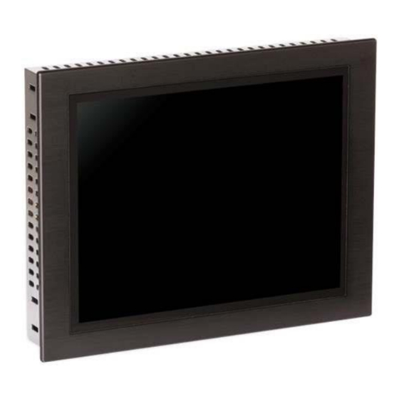
Control Panel
ETV 0853-3
The control panel is an intelligent terminal for programming and visualization of automated
processes. Process diagnosis as well as operating and monitoring automated procedures
is simplified using this terminal.
A projective capacitive touch screen serves as the input medium for process data and
parameters. The output is shown on an 8.4" SVGA TFT color display.
With the LSE mask editor, graphics can be created on the PC, then stored and displayed
on the terminal.
The available interface connections can be used to exchange process data or configure the
terminal. A micro SD card serves as the storage medium for the operating system, applica-
tion and application data.
The integrated, high-performance VARAN bus can be used to control I/O modules directly.
12.04.2017
Page 1
Advertisement
Table of Contents

Related Manuals for SIGMATEK ETV 0853-3


Summary of Contents for SIGMATEK ETV 0853-3
- Page 1 CONTROL PANEL ETV 0853-3 Control Panel ETV 0853-3 The control panel is an intelligent terminal for programming and visualization of automated processes. Process diagnosis as well as operating and monitoring automated procedures is simplified using this terminal. A projective capacitive touch screen serves as the input medium for process data and parameters.
-
Page 2: Table Of Contents
ETV 0853-3 CONTROL PANEL Contents Technical Data ....................... 3 Cleaning the Touch Screen .................. 7 Mechanical Dimensions ..................8 Connector Layout ....................9 Connections on Rear and Bottom .................. 9 Buffer Battery ...................... 14 Exchanging the Battery ..................15 BIOS ........................17 Cooling ......................... -
Page 3: Technical Data
CONTROL PANEL ETV 0853-3 Technical Data Performance data Processor EDGE-Technology X86 compatible Internal cache 32-kbyte L1 Cache 256-kbyte L2 Cache BIOS Internal program and data memory 256 Mbytes (DDR2 RAM) Internal remnant data memory 512 Kbytes Internal storage device (IDE) - Page 4 ETV 0853-3 CONTROL PANEL Electrical requirements Supply voltage Typically +24 V DC Minimum +18 V DC Maximum +30 V DC Current consumption of the Typically 350 mA Maximum 400 mA supply +24 V (with no external devices connected) (with external devices connected) Starting current Maximum 27 A for 9 µs...
- Page 5 Cleaning See Chapter Cleaning the Touch Screen The ETV 0853-3 has a projective capacitive touch screen is built in, with which 2-finger input, Zoom and gesture functions can be implemented. Data can be input using fingers, a project capacitive touch pen and while wearing thin gloves. With thick gloves, operating the touch screen is not possible.
- Page 6 ETV 0853-3 CONTROL PANEL Digital Outputs Number of … Short-circuit proof Maximum continuous current load allowed per channel Maximum total current 6 A (100 % of on-time) (all 8-channels) 1 V Voltage drop over power supply (output active) 12 µA...
-
Page 7: Cleaning The Touch Screen
CONTROL PANEL ETV 0853-3 Cleaning the Touch Screen CAUTION: Before cleaning the touch screen, the terminal must first be turned off to avoid unin- tentionally triggering functions or commands! The terminal's touch screen can only be cleaned with a soft, damp cloth. To dampen the cloth, a screen-cleaning solution such as an antistatic foam, water with detergent or alcohol should be used. -
Page 8: Mechanical Dimensions
ETV 0853-3 CONTROL PANEL Mechanical Dimensions Page 8 12.04.2017... -
Page 9: Connector Layout
CONTROL PANEL ETV 0853-3 Connector Layout Connections on Rear and Bottom X1: Power plug Function +24 V DC DIG IOs +24 V DC X2: CAN Function CAN A (CAN LOW) CAN B (High) CAN A (CAN LOW) CAN B (High) n.c. - Page 10 ETV 0853-3 CONTROL PANEL X3 and X8: 8 digital inputs, 8 digital outputs X3: Pin assignment Function OUTPUT 1 OUTPUT 2 OUTPUT 3 OUTPUT 4 Input 1 Input 2 Input 3 Input 4 X8 Pin assignment Function OUTPUT 5 OUTPUT 6...
- Page 11 Problems can arise if a control is connected to an IP network, which contains mod- ules that are not running with a SIGMATEK operating system. With such devices, Ethernet packets could be sent to the control with such a high frequency (i.e. broad- casts), that the high interrupt load could cause a real-time runtime error or runtime error.
- Page 12 ETV 0853-3 CONTROL PANEL X6: USB 1.1 (Mini-B) Function +5 V n.c. n.c. = do not use X7: USB 2.0 (Type A, Full Speed 12 Mbit/s) Function +5 V_USB It should be noted that many of the USB devices on the market do not comply with USB specifications;...
- Page 13 Power supply: 4-pin Phoenix plug with screw terminal technology MC1, 5/4-ST-3.5 4-pin Phoenix plug with spring terminal FK-MCP1, 5/4-ST-3.5 Digital I/Os: 2 x 8-pin Phoenix plug with spring terminal FMC1, 5/8-ST-3.5 The complete CKL 213 connector set is available from SIGMATEK under the article number 12-600-213. 12.04.2017 Page 13...
-
Page 14: Buffer Battery
ETV 0853-3 CONTROL PANEL Buffer Battery The exchangeable buffer battery ensures that the clock time (RTC) is preserved in the absence of a supply voltage. A lithium battery is installed at the manufacturer. The battery has enough capacity to preserve data in the absence of a supply voltage for up to 7 years. -
Page 15: Exchanging The Battery
CONTROL PANEL ETV 0853-3 Exchanging the Battery 1. Disconnect the power to the ETV. 2. Open the locking screws on the back f the terminal with a 6-edge screwdriver 2 mm: 12.04.2017 Page 15... - Page 16 ETV 0853-3 CONTROL PANEL 4. Using the strap, remove the battery from the holder (see arrow). 5. Place the new battery in the holder with the correct polarity (+ Pole toward the frontside) and replace the cover. Page 16 12.04.2017...
-
Page 17: Bios
CONTROL PANEL ETV 0853-3 BIOS The BIOS is configured so that the Salamander operating system is booted from the SD card. Cooling The terminal's power loss can reach up to 10 Watts. To ensure the necessary air circula- tion for cooling, the following mounting instructions must be followed! -
Page 18: Wiring Guidelines
ETV 0853-3 CONTROL PANEL Wiring Guidelines Earth Connection The terminal must be connected to earth through the mounting on control cabinet or over the terminal provided. It is important to create a low-ohm earth connection, only then can error-free operation be guaranteed. The earth connection should have the maximum cross section and the largest electrical surface possible. -
Page 19: Can Bus Setup
CONTROL PANEL ETV 0853-3 CAN Bus Setup This section explains how to correctly configure the CAN bus. The following parameters must first be set: Station number and data transfer rate. CAN bus station number Each CAN bus station is assigned its own station number. With this station number, data can be exchanged with other stations connected to the bus. -
Page 20: Can Bus Termination
ETV 0853-3 CONTROL PANEL CAN Bus Termination In a CAN bus system, both end modules must be terminated. This is necessary to avoid transmission errors caused by reflections in the line. Device 1 Device 2 Device 3 Device n e.g. CPU e.g. -
Page 21: Process Diagram
CONTROL PANEL ETV 0853-3 Process Diagram 12.04.2017 Page 21... -
Page 22: Status And Error Messages
ETV 0853-3 CONTROL PANEL Status and Error Messages Status and error messages are displayed in the LASAL Class software status test. POINTER or CHKSUM messages can also be shown on the terminal screen. Number Message Definition Cause/solution RUN RAM The user program is currently running in Info RAM. - Page 23 CONTROL PANEL ETV 0853-3 Watchdog The program was interrupted through the Possible Causes: watchdog logic. Interrupts the user program blocked of a long time period (STI instruction forgotten) Programming error in a hardware interrupt. INB, OUTB, INW, OUTW instruc- tions used incorrectly.
- Page 24 ETV 0853-3 CONTROL PANEL PROG END The memory module was successfully Info completed. PROG MEMO The CPU is currently programming the Info memory module. STOP BRKPT The CPU was stopped by a breakpoint in Info the program. CPU STOP The CPU was stopped by the program- Info ming software.
- Page 25 OP INSTALLED The operating system has been rein- Info stalled. OS TOO LONG The operating system cannot be loaded; Restart; report error to Sigmatek. too little memory. NO OPERATING Boot loader message. Restart; report error to Sigmatek. SYSTEM No operating system found in RAM.
- Page 26 An error has occurred during a floating- ERROR point operation. DIAS-RISC-ERROR Error from the Intelligent DIASMaster. Restart; report error to Sigmatek. INTERNAL ERROR An internal error has occurred, all appli- Restart; report error to Sigmatek. cations are stopped. FILE ERROR An error has occurred during a file operation.
- Page 27 CONTROL PANEL ETV 0853-3 REALTIME RUNTIME The total duration of all real-time objects Solution: exceeds the maximum time; the time Optimize the application's cannot be configured. realtime task (RtWork). 2 ms for 386 CPUs Reduce the clock time for the 1 ms for all other CPUs realtime task of all objects.
- Page 28 ETV 0853-3 CONTROL PANEL C_READY The CPU is ready for operation. C_OK The CPU is ready for operation. C_UNKNOWN_CID An unknown class from a stand-along or embedded object: unknown base class. C_UNKNOWN_CONSTR The operating system class cannot be created; the operating system is probably wrong.
- Page 29 CONTROL PANEL ETV 0853-3 REBOOT The operating system is restarted. LSL SAVE LSL LOAD CONTINUE PRERUN The application is started. PRERESET The application is ended. CONNECTION BREAK 12.04.2017 Page 29...
-
Page 30: Application Exceptions
ETV 0853-3 CONTROL PANEL Application exceptions SRAM and IRQ routines Writing remnant data during interrupt routines is not allowed and leads to a system crash. SRAM and consistency of changed data If more than 32 different sectors are changed (512 bytes each) shortly before shutting down the voltage supply while the user program is writing to the Micro SD card, this can sometimes lead to partial loss of remnant data. -
Page 31: Note On Sram Behavior
CONTROL PANEL ETV 0853-3 Note on SRAM Behavior Because the SRAM (remnant memory) is emulated via the microSD card, there are two different mechanisms for saving SRAM data to the microSD card: 1. Cyclic writing when data is changed (default) 2. -
Page 32: Recommended Shielding For Varan
It is recommended to avoid placing Varan bus lines parallel to power cables whenever possible. SIGMATEK recommends the use of CAT5e industrial Ethernet bus cables. For the shielding, an S-FTP cable should be used. An S-FTP bus is a symmetric, multi-wire cable with unshielded pairs. For the total shield- ing, a combination of foil and braiding is used. -
Page 33: Wiring From The Control Cabinet To An External Varan Component
CONTROL PANEL ETV 0853-3 1. Wiring from the Control Cabinet to an External VARAN Component If the Ethernet lines are connected from a VARAN component to a VARAN node located outside the control cabinet, the shielding should be placed at the entry point to the control cabinet housing. -
Page 34: Wiring Outside Of The Control Cabinet
ETV 0853-3 CONTROL PANEL 2. Wiring Outside of the Control Cabinet If a VARAN bus cable must be placed outside of the control cabinet only, no additional shield connection is required. This requires that only IP67 modules and connectors be used. -
Page 35: Shielding For Wiring Within The Control Cabinet
CONTROL PANEL ETV 0853-3 3. Shielding for Wiring Within the Control Cabinet Sources of strong electromagnetic noise located within the control cabinet (drives, Trans- formers, etc.) can induce interference in a VARAN bus line. Voltage spikes are dissipated over the metallic housing of a RJ45 connector. Noise is conducted over the control cabinet without additional measures needed on the circuit board of electronic components. -
Page 36: Connecting Noise-Generating Components
ETV 0853-3 CONTROL PANEL 4. Connecting Noise-Generating Components When connecting power lines to the bus that generate strong electromagnetic noise, the correct shielding is also important. The shielding should be placed before a power element (or group of power elements). -
Page 37: Shielding Between Two Control Cabinets
CONTROL PANEL ETV 0853-3 5. Shielding Between Two Control Cabinets If two control cabinets must be connected over a VARAN bus, it is recommended that the shielding be located at the entry points of each cabinet. Noise is therefore prevented from reaching the electronic components in both cabinets. - Page 38 ETV 0853-3 CONTROL PANEL Page 38 12.04.2017...
Need help?
Do you have a question about the ETV 0853-3 and is the answer not in the manual?
Questions and answers