Table of Contents
Advertisement
Quick Links
CONTROL PANEL
ETV 1991
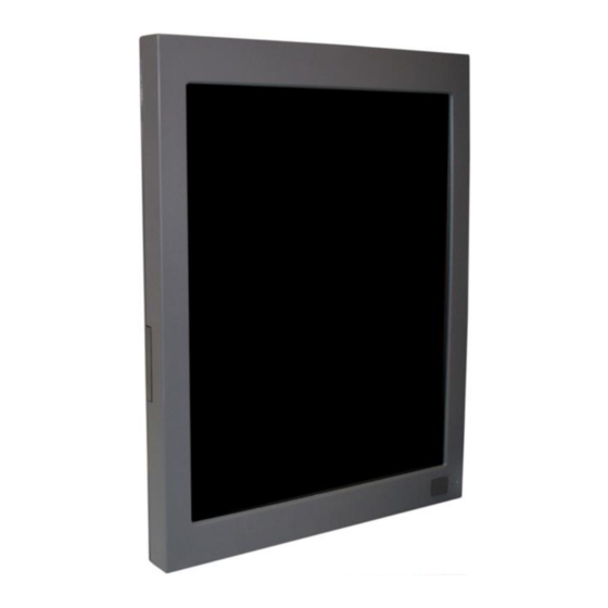
Control Panel
ETV 1991
The control panel is an intelligent terminal for programming and visualization of automated
processes. Process diagnosis as well as operating and monitoring automated procedures
is simplified using this terminal.
A touch screen serves as the input medium for process data and parameters. The output
is shown on a 19" SXGA TFT color display.
With the LSE mask editor, graphics can be created on the PC, then stored and displayed
on the terminal.
The available interface connections can be used to exchange process data or configure
the terminal. An internal Compact Flash serves as the storage medium for the operating
system, application and application data.
The integrated, high-performance VARAN bus enables the direct control of I/O modules.
21.06.2018
Page 1
Advertisement
Table of Contents

Related Manuals for SIGMATEK ETV 1991


Summary of Contents for SIGMATEK ETV 1991
- Page 1 CONTROL PANEL ETV 1991 Control Panel ETV 1991 The control panel is an intelligent terminal for programming and visualization of automated processes. Process diagnosis as well as operating and monitoring automated procedures is simplified using this terminal. A touch screen serves as the input medium for process data and parameters. The output is shown on a 19"...
-
Page 2: Table Of Contents
ETV 1991 CONTROL PANEL Contents Technical Data .................... 3 Performance data ..................3 Electrical requirements ................4 Terminal ....................4 Control unit ....................4 Display ..................... 4 Miscellaneous ..................5 Environmental conditions................. 5 Mechanical Dimensions ................6 Chemical Resistance .................. 7 Decorative foil .................. -
Page 3: Technical Data
CONTROL PANEL ETV 1991 Technical Data Performance data Processor 1.6 GHz Intel Atom N270 Cache 512 Kbytes 1st Level BIOS AMI BIOS SDRAM (SO-DIMM 200-Pin) 256-Mbyte DDR2 Compact Flash (Type I) 1 Gbyte SRAM 512 Kbytes (battery buffered) Interface connections... -
Page 4: Electrical Requirements
ETV 1991 CONTROL PANEL Electrical requirements Supply voltage Minimum +18 V DC Maximum +30 V DC Current consumption of voltage Typically 1.5 A (at +24 V) (without external devices connected) supply Starting current Maximum 20 A for <5 ms Terminal... -
Page 5: Miscellaneous
CONTROL PANEL ETV 1991 Miscellaneous Article number 12-230-1991 Hardware version Software Macro LASAL operating system Project back-up Internally on Compact Flash Environmental conditions -20 – +60 °C Storage temperature 0 – +50 °C Operating temperature Humidity 10 - 90 %, non-condensing... -
Page 6: Mechanical Dimensions
ETV 1991 CONTROL PANEL Mechanical Dimensions Page 6 21.06.2018... -
Page 7: Chemical Resistance
CONTROL PANEL ETV 1991 Chemical Resistance Decorative foil Solution Effect over time 1 hour 24 hours Methyl, ethyl, ketone None None Cyklohexanol None None Acetone None None Ethanol None None Benzyl alcohol 1.1.1.Trichlorethan (Genklene) None None Perchloroethylene (Perklone) None None... -
Page 8: Touch Foil
ETV 1991 CONTROL PANEL Touch foil Solution Visual Effect Coal tar oil / toluene None Trichloroethylene None Acetone None Alcohol None Benzine None Machine oil None Ammonia None Glass cleaner None Mayonnaise None Ketchup None Wine None Salad oil None... -
Page 9: Connector Layout
Two status LEDs are located on the front (one red and one green LED). LED status Definition Red and green light simultaneously The ETV 1991 is booting Red LED blinks only The operating system is loading The green LED blinks only The application is running 21.06.2018... -
Page 10: Rear Connectors
ETV 1991 CONTROL PANEL Rear connectors X8: power plug (FK-MCP 1,5/4-ST-3,5) Pin 1 Function +24 V supply +24 V supply X1 USB Type A V1.1 Function +5 V X2: CAN (Weidmüller B2L 3,5/8) Function CAN A (CAN LOW) CAN B (High) - Page 11 Problems can arise if a control is connected to an IP network, which contains mod- ules that are not running with a SIGMATEK operating system. With such devices, Ethernet packets could be sent to the control with such a high frequency (i.e. broad- casts), that the high interrupt load could cause a real-time runtime error or runtime error.
-
Page 12: Chip-Card Reader
ETV 1991 CONTROL PANEL X4, X5: VARAN-Bus (RJ45) Function TX/RX+ TX/RX- RX/TX+ n.c. n.c. RX/TX- n.c. n.c. n.c. = do not use More information on the VARAN bus can be found in the VARAN bus specifications! Chip-card reader A chip-card reader can be added as shown below. The order number for the chip-card reader is: 12-235-011. -
Page 13: Storage Media
CONTROL PANEL ETV 1991 Storage Media It is recommended that only storage media provided by SIGMATEK (CompactFlash cards, microSD cards etc.) be used. The number of read and write actions have a significant influence on the lifespan of the storage media. -
Page 14: Battery Exchange
ETV 1991 CONTROL PANEL Battery Exchange Switch off the terminal. Loosen the marked screws and open the housing. The corresponding screws are: 2 pieces Combination pan-head screw M3x6 10 pieces PT screws countersunk head KA40x10 Remove the battery and replace it with the new battery. -
Page 15: Wiring Guidelines
CONTROL PANEL ETV 1991 Wiring Guidelines Earth Connection The terminal must be connected to earth through the mounting on control cabinet or over the terminal provided. It is important to create a low-ohm earth connection, only then can error-free operation be guaranteed. The earth connection should have the maximum cross section and the largest electrical surface possible. -
Page 16: Shielding
ETV 1991 CONTROL PANEL Shielding For the CAN and DIAS bus wiring, twisted pair shielded wires should be used. The cable shielding must be connected to earth either directly before the terminal over a large sur- face and with low Ohms using grounding clamps or with a blade terminal. With Ethernet and the VARAN bus, CAT5 cables with shielded RJ45 connectors are required. -
Page 17: Dias Bus With C-Dias Modules
CONTROL PANEL ETV 1991 DIAS bus with C-DIAS modules To ensure a good bus connection, several wiring guidelines must be followed: • The cable used must be designed for the data transfer speed: Data cable (10 MBit, 2 x 2 wire TWISTED PAIR, shielded) E.g.: LAPPKABEL / UNITRONIC-BUSLEITUNG FD P LD... -
Page 18: Can Bus Termination
ETV 1991 CONTROL PANEL CAN Bus Termination In a CAN bus system, both end modules must be terminated. This is necessary to avoid transmission errors caused by reflections in the line. Module 1 Module 2 Module 3 Module n I.e. CPU I.e. -
Page 19: Process Diagram
CONTROL PANEL ETV 1991 Process Diagram Main voltage Online with Lasal Software? Output of a Output of a reset of the reset of the peripheral modules peripheral modules Deletion of Deletion of specific specific data areas data areas Program in... -
Page 20: Status And Error Messages
ETV 1991 CONTROL PANEL Status and Error Messages Status and error messages are displayed in the LASAL Class software status test. If the CPU has a status display, the status or error number is also show here as well. POINTER or CHKSUM messages are shown on the terminal screen. - Page 21 CONTROL PANEL ETV 1991 Watchdog The program was interrupted through Possible Causes: the watchdog logic. - Interrupts the user program blocked of a long time period (STI instruction forgotten) - Programming error in a hardware interrupt. - INB, OUTB, INW, OUTW instruc- tions used incorrectly.
- Page 22 ETV 1991 CONTROL PANEL STOP BRKPT The CPU was stopped by a breakpoint in the program. CPU STOP The CPU was stopped by the PG software (F6 HALT in status test). INT ERROR The CPU has triggered a false interrupt...
- Page 23 CONTROL PANEL ETV 1991 WAIT The CPU is busy. OP PROG The operating system is currently being reprogrammed. OP IN- The operating system has been rein- STALLED stalled. OS TOO The operating system cannot be loaded; LONG too little memory.
- Page 24 ERROR DIAS-RISC- Error from the Intelligent DIASMaster. ERROR INTERNAL An internal error has occurred, all appli- Restart; report error to Sigmatek. ERROR cations are stopped. FILE ERROR An error has occurred during a file operation. DEBUG Internal error.
- Page 25 CONTROL PANEL ETV 1991 USER User-definable code. FINED 3 USER User-definable code. FINED 4 C_INIT Initialization start; the configuration is run. C_RUNRAM The LASAL project was successfully started from RAM. C_RUNROM The LASAL project was successfully started from ROM. C_RUNTIME C_READY The CPU is ready for operation.
- Page 26 ETV 1991 CONTROL PANEL LINKING An error has occurred while linking. An ERROR error messaged is generated in the LASAL status window. LINKING Linking is complete. DONE OP BURN The operating system is currently being burned into the Flash memory.
-
Page 27: Recommended Shielding For Varan
It is recommended to avoid placing Varan bus lines parallel to power cables whenever possible. SIGMATEK recommends the use of CAT5e industrial Ethernet bus cables. For the shielding, an S-FTP cable should be used. An S-FTP bus is a symmetric, multi-wire cable with unshielded pairs. For the total shield- ing, a combination of foil and braiding is used. -
Page 28: Wiring From The Control Cabinet To An External Varan Component
ETV 1991 CONTROL PANEL 1. Wiring from the Control Cabinet to an External VARAN Com- ponent If the Ethernet lines are connected from a VARAN component to a VARAN node located outside the control cabinet, the shielding should be placed at the entry point to the control cabinet housing. -
Page 29: Wiring Outside Of The Control Cabinet
CONTROL PANEL ETV 1991 2. Wiring Outside of the Control Cabinet If a VARAN bus cable must be placed outside of the control cabinet only, no additional shield connection is required. This requires that only IP67 modules and connectors be used. -
Page 30: Shielding For Wiring Within The Control Cabinet
ETV 1991 CONTROL PANEL 3. Shielding for Wiring Within the Control Cabinet Sources of strong electromagnetic noise located within the control cabinet (drives, Trans- formers, etc.) can induce interference in a VARAN bus line. Voltage spikes are dissipated over the metallic housing of a RJ45 connector. Noise is conducted over the control cabinet without additional measures needed on the circuit board of electronic components. -
Page 31: Connecting Noise-Generating Components
CONTROL PANEL ETV 1991 4. Connecting Noise-Generating Components When connecting power lines to the bus that generate strong electromagnetic noise, the correct shielding is also important. The shielding should be placed before a power element (or group of power elements). -
Page 32: Shielding Between Two Control Cabinets
ETV 1991 CONTROL PANEL 5. Shielding Between Two Control Cabinets If two control cabinets must be connected over a VARAN bus, it is recommended that the shielding be located at the entry points of each cabinet. Noise is therefore prevented from reaching the electronic components in both cabinets. -
Page 33: Cleaning The Touch Screen
CONTROL PANEL ETV 1991 Cleaning the Touch Screen CAUTION! Before cleaning the touch screen, the terminal must first be turned off to avoid unin- tentionally triggering functions or commands! The terminal's touch screen can only be cleaned with a soft, damp cloth. To dampen the cloth, a screen-cleaning solution such as an antistatic foam, water with detergent or alcohol should be used. - Page 34 ETV 1991 CONTROL PANEL Page 34 21.06.2018...
Need help?
Do you have a question about the ETV 1991 and is the answer not in the manual?
Questions and answers