
Subscribe to Our Youtube Channel
Related Manuals for HACH LANGE TU5400 sc


Summary of Contents for HACH LANGE TU5400 sc
- Page 1 DOC023.52.90501 TU5400 sc/TU5300 sc 09/2014, Edition 1 Basic User Manual -BETA DRAFT-...
- Page 2 -BETA DRAFT-...
-
Page 3: Table Of Contents
650 nm, maximum 1 mW laser Laser Class 2 laser product: contains an embedded non user-serviceable class 2 laser Measurement units TU5300 sc: NTU, FNU, TE/F, FTU, EBC; TU5400 sc: NTU, FNU, TE/F, FTU, EBC, mNTU Range 0 to 700 NTU Stray light <0.010 NTU... -
Page 4: General Information
Specification Details ® Calibration options StablCal : at 20 NTU from 0 to 40 NTU; at 20 NTU and 600 NTU for full range User prepared formazin: at 20 NTU from 0 to 40 NTU; at 20 NTU and 600 NTU for full range Custom calibration for up to 6-point calibrations ®... - Page 5 Safety information N O T I C E The manufacturer is not responsible for any damages due to misapplication or misuse of this product including, without limitation, direct, incidental and consequential damages, and disclaims such damages to the full extent permitted under applicable law.
- Page 6 This symbol identifies a risk of chemical harm and indicates that only individuals qualified and trained to work with chemicals should handle chemicals or perform maintenance on chemical delivery systems associated with the equipment. This symbol indicates radio waves. Class 2 laser product D A N G E R Personal injury hazard.
- Page 7 Safety information for RFID modules W A R N I N G Multiple hazards. Do not disassemble the instrument for maintenance. If the internal components must be cleaned or repaired, contact the manufacturer. W A R N I N G Electromagnetic radiation hazard.
- Page 8 Refer to the current safety data sheets (MSDS/SDS) for safety protocols. The TU5300 sc and the TU5400 sc sensors are used with an sc controller to measure low range turbidity primarily in water purification water applications and in seawater with high salt concentrations.
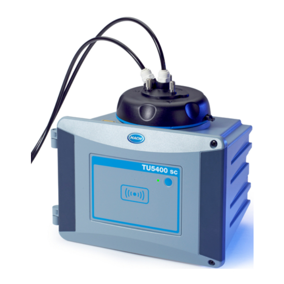
- Page 9 Figure 1 Product overview 1 User-specified button 8 Process head (shown) or cleaning head (optional) 2 Status indicator light 9 Process head water drain 3 RFID unit (optional) 10 Process head (open) 4 Knurled screws (3x) for (≤ 40 ºC (104 ºF) or high- 11 Process head (closed) temperature screws (3x) for (40 to 70 ºC (104 to 158 ºF)) for the vial access cover...
-
Page 10: Installation
Figure 2 Product components 1 Turbidity sensor with 1.6 m cable (3 ft 3⅜ in.) 6 Screws, bracket to sensor (4x), 4 x 16 mm 2 Vial removal tool 7 Screws for tubing clips (4x), 2.2 x 6 mm 3 Maintenance rack 8 Tubing clips (4x) 4 Vial wiper 9 Bracket for tubing attachments and optional... - Page 11 Figure 3 Installation overview 1 Maintenance rack 4 Sample inlet 2 Process head 5 Sample outlet 3 Controller 6 Sensor Wall mount Install with a bracket D A N G E R Electrocution hazard. Remove power from the instrument before this procedure is started. To install the sensor on a wall with the mounting bracket, refer to the illustrated steps that follow.
- Page 12 -BETA DRAFT- 12 English...
- Page 13 Install without a bracket D A N G E R Electrocution hazard. Remove power from the instrument before this procedure is started. As an alternative, attach the sensor directly to a wall. Refer to the illustrated steps that follow. Make sure to remove the thin, plastic film from the mounting holes on the back of the instrument.
- Page 14 Install the desiccant cartridge Refer to the documentation supplied with the desiccant cartridge for initial installation. Make sure that the indicator on the desiccant cartridge is blue. Refer to Figure Figure 4 Desiccant cartridge overview 1 Label (LWWYY = lot number, week and year) 2 Indicator (blue = OK, pink = expired) Connect to an sc controller Connect the sensor to the quick-connect fitting of an sc controller.
- Page 15 Set the controller power to on after the connection to the sensor is made. When the sensor is set to on, the status light is activated. Refer to Status indicator light on page 15. Status indicator light When the controller power is set to on, the status indicator light on the sensor shows. Refer to Figure 1 on page 9.
- Page 16 Table 2 Status indicator light definitions (continued) Light color Definition Blue (flashes) Calibration process (measurement) Verification process (measurement) Reading RFID. Sound signal occurs when the reading is OK. Plumbing Plumb the sensor W A R N I N G Explosion hazard. Make sure that the drain tube is free of all obstructions. If the drain tube has a blockage or is pinched or bent, high pressure can build up in the instrument.
-
Page 17: Startup
Startup Set up the sensor Use the setup menu to start an automatic vial cleaning (optional) and to select calibration, verification, configuration and maintenance options. 1. Push menu. 2. Select SENSOR SETUP. 3. Select an option. Option Description WIPE (optional) Starts an automatic cleaning process to clean the vial if an automatic mechanical cleaning unit is installed. - Page 18 C A U T I O N Multiple hazards. Only qualified personnel must conduct the tasks described in this section of the document. C A U T I O N Personal injury hazard. Never remove covers from the instrument. This is a laser-based instrument and the user risks injury if exposed to the laser.
- Page 19 Option Description COUNTERS Shows operational and maintenance times. Refer to the expanded manual on the manufacturer's website. MAINTENANCE Starts an instructed menu process to replace or clean the vial, replace the wiper or the desiccant cartridge. WIPE—Starts a wiper cleaning. OUTPUT MODE—Selects the output behaviour during maintenance (default: hold).
- Page 20 Clean the instrument N O T I C E Do not use solvents to clean the instrument. The instrument is maintenance free. Regular cleaning is not necessary for normal operation. If the exterior of the instrument becomes dirty, wipe the instrument surfaces with a clean, moist cloth. Clean the vial with the wiper N O T I C E Carefully put the wiper into the vial so that no water can spill out.
- Page 21 -BETA DRAFT- English 21...
-
Page 22: Troubleshooting
Replace the desiccant cartridge The controller will show when the desiccant cartridge replacement is due. When the desiccant is expired, the indicator on the desiccant cartridge is pink. Make sure that the sensor is connected to the controller. 1. Push menu. 2. - Page 23 -BETA DRAFT-...
- Page 24 Tel. +49 (0) 2 11 52 88-320 SWITZERLAND Fax (970) 669-2932 Fax +49 (0) 2 11 52 88-210 Tel. +41 22 594 6400 orders@hach.com info@hach-lange.de Fax +41 22 594 6499 www.hach.com www.hach-lange.de © Hach Company/Hach Lange GmbH, 2014. All rights reserved. Printed in Germany. -BETA DRAFT-...
Need help?
Do you have a question about the TU5400 sc and is the answer not in the manual?
Questions and answers