Table of Contents
Advertisement
Advertisement
Table of Contents

Subscribe to Our Youtube Channel
Related Manuals for HACH LANGE ORBISPHERE 3650


Summary of Contents for HACH LANGE ORBISPHERE 3650
- Page 1 ORBISPHERE Model 3650 USER MANUAL February 2009, Revision F...
-
Page 3: Table Of Contents
Table of Contents ......................3 Section 1 General Information 1.1 Disclaimer ............................ 3 1.2 Safety information ........................3 1.2.1 Use of hazard information ....................3 1.2.2 Service and repairs ......................3 1.2.3 Precautionary labels......................4 1.3 Product recycling information....................... 5 1.4 Product disposal .......................... - Page 4 Table of Contents 5.4.7 Dual use (model 3650/113 only) ..................32 ........................33 Section 6 Calibrations 6.1 Pressure calibration........................33 6.2 Sensor calibration........................34 6.2.1 Calibration in a span gas....................34 6.2.2 Calibration in line.......................35 6.2.3 Calibration in air ........................36 6.3 Calibration range checking......................36 ................37 Section 7 Maintenance and Troubleshooting 7.1 Maintenance..........................37 7.1.1 Instrument batteries......................37...
-
Page 5: Section 1 General Information
Copyright © 2009 by Hach Lange. All rights reserved. No part of the contents of this manual may be reproduced or transmitted in any form or by any means without the written permission of Hach Lange. -
Page 6: Precautionary Labels
General Information 1.2.3 Precautionary labels Read all labels and tags attached to the instrument. Personal injury or damage to the instrument could occur if not observed. This symbol, when noted on a product enclosure or barrier, indicates that a risk of electrical shock and/or electrocution exists and indicates that only individuals qualified to work with hazardous voltages should open the enclosure or remove the barrier. -
Page 7: Product Recycling Information
General Information 1.3 Product recycling information ENGLISH Electrical equipment marked with this symbol may not be disposed of in European public disposal systems after 12 August 2005. In conformity with European local and national regulations (EU Directive 2002/96/EC), European electrical equipment users must now return old or end-of-life equipment to the manufacturer for disposal at no charge to the user. -
Page 8: General Information
General Information SVENSKA Elektronikutrustning som är märkt med denna symbol kanske inte kan lämnas in på europeiska offentliga sopstationer efter 2005-08-12. Enligt europeiska lokala och nationella föreskrifter (EU-direktiv 2002/96/EC) måste användare av elektronikutrustning i Europa nu återlämna gammal eller utrangerad utrustning till tillverkaren för kassering utan kostnad för användaren. Obs! Om du ska återlämna utrustning för återvinning ska du kontakta tillverkaren av utrustningen eller återförsäljaren för att få... -
Page 9: Product Disposal
European public disposal systems after 12 August 2005. Hach Lange will offer to take back (free of charge to the customer) any old, unserviceable or redundant analyzers and systems which carry the above symbol, and which were originally supplied by Hach Lange. -
Page 10: Restriction Of Hazardous Substances (Rohs)
Currently, monitoring and control instruments do not fall within the scope of the RoHS Directive, however Hach Lange has taken the decision to adopt the recommendations in the Directive as the target for all future product design and component purchasing. -
Page 11: Section 2 Specifications
Section 2 Specifications 2.1 General technical data Batteries: two C-type cells, NiCd or alkaline, each 26 x Power Supply 50mm, 2.4 - 3volts total Power Autonomy 40 hours continuous use Signal Drift <0.5% of reading between service Serial Output (RS232) Baud rate: 9600;... - Page 12 Specifications...
-
Page 13: Section 3 Installation
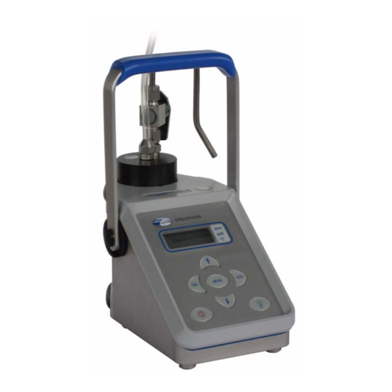
Installation This section provides necessary information to install and connect the instrument. Should you have any questions, do not hesitate to contact your Hach Lange representative regarding the installation procedure. The ORBISPHERE 3650 instrument is a self-contained portable analyzer, configured to make oxygen concentration measurements in gaseous or liquid samples, with Electrochemical (EC) Sensors. -
Page 14: Sensor Installation
Installation 3.1 Sensor installation The sensor has a threaded collar and calibration cap, and a screw-on protection cap to prevent disturbances to the membrane. A plastic screw-on base at its rear provides a stand for servicing, and protects the sensor's screw-on 10-pin LEMO connection. Figure 2 Electrochemical Sensor Components - Exploded View The electrochemical (EC) sensor connects to the instrument base through a 10-pin LEMO connector. -
Page 15: Sample Tube Adapter (Optional)
Installation 3.3 Sample tube adapter (optional) A model 32051 sample tube adapter can be attached to the flow chamber's inlet tubing. This adapter, in turn, attaches to 6 mm or ¼ inch stainless steel or flexible tubing using rubber gasket model 32813 (or, for 8 mm tubing, rubber gasket model 32814). -
Page 16: Instrument - Pc Connection
Installation 3.5.2 Instrument - PC Connection An RS-232 cable is supplied with the instrument, with a 6-pin LEMO plug on one end and a 9-pin D-Type plug on the other. RS232 Signal Pin 1 Transmitted data (TXD) Pin 1 Not Used Pin 2 Received data (RXD) Pin 2 RS-232 Transmitted Data (TXD) Pin 3 Not Used... -
Page 17: Installation Completion Check List
Installation 3.6 Installation completion check list 3.6.1 Batteries The instrument is designed to work on battery power. If battery power should drop, a LO BAT warning appears in the instrument LCD's top-left corner, and they should be replaced. 3.6.2 Instrument clock setting If you use the instrument to store measurements for downloading to a PC, you should verify the date and time settings of the instrument's internal clock, as described in Clock settings on... -
Page 18: Flow Chamber
Installation You will get a better look at all these components during your first sensor service. Before making a measurement, check the sensor head to see that: The membrane mounting ring is firmly in place, • The membrane surface is smooth and wrinkle-free, •... -
Page 19: Section 4 Operating Information
Section 4 Operating Information 4.1 Operating controls The front panel of the instrument has a three-digit liquid crystal display (LCD). The LCD includes a right-side marker to distinguish between gas concentration and temperature display. This marker also indicates the measurement display units (ppm, ppb, %, etc.) depending on the instrument model. - Page 20 Operating Information Toggles between gas concentration and temperature measurement displays in measurement mode, increases or decreases the storage number during storage or memory view, or sets a calibration value during calibration To start the analyzer, press the keyboard switch (located bottom left of the keyboard). POWER When you turn power on, the instrument displays its model number briefly, and then starts in measurement mode.
-
Page 21: Taking Measurements
Operating Information 4.2 Taking measurements Once the system is calibrated, you should be able to begin taking measurements. Connect the top-mounted inlet to accept your sample, typically this is accomplished by connection to a sampling valve. The sample flow can be regulated by adjusting the knurled stainless steel knob on top of the flow chamber. -
Page 22: Storing Measurements In The Instrument
Operating Information 4.3 Storing measurements in the instrument The instrument will store up to 500 gas measurement values, labeled by numbers 0 through 499, along with the current date and time of each measurement. You have the choice of acquiring this information manually or automatically, as described below. Before storing measurements, you should verify the date and time settings of the instrument's internal clock, as described in Clock settings on page... -
Page 23: Manual Data Acquisition
Operating Information 4.3.2 Manual data acquisition Note: You cannot store measurement data manually if the instrument has already been set up to store the data automatically. 1. For the first measurement you wish to store, press the button once to display a sample number. -
Page 24: Viewing Stored Measurements
Operating Information 4.3.3 Viewing stored measurements 1. Switch the instrument (by pressing key) POWER 2. Hold down the button while Up Arrow switching the instrument back ON. The LCD displays a sample location number. 3. Scroll through the numbered sample locations of all the stored values using the buttons. -
Page 25: Altering The Sampling Point Descriptions
Operating Information 4.4.2 Altering the sampling point descriptions For help in identifying the locations of various sampling points that are stored by the instrument, you may choose the Sampling Point Description command from the Logger menu to bring up the dialog box. The measurement values to be placed in positions 0 through 499 (identified as Text 0, Text 1... -
Page 26: Clearing Stored Values
Operating Information 4.4.6 Clearing stored values To clear all the values stored in the instrument via the WinLog97 program, choose the Clear Data command from the Logger menu. Since this action will clear the storage memory of the instrument, a warning appears first. Choose OK to bring up the next dialog box to confirm the clear action. - Page 27 Operating Information The chart updating rate is determined by the time scale selected. Timebase Updating Rate* Maximum Samples (10 divisions) 30 Seconds/Division 5 Seconds/Sample 1 Minute/Division 5 Seconds/Sample 10 Minutes/Division 5 Seconds/Sample 1,200 30 Minutes/Division 9 Seconds/Sample 2,000 1 Hour/Division 18 Seconds/Sample 2,000 2.5 Hours/Division...
- Page 28 Operating Information...
-
Page 29: Section 5 Options Setup
Section 5 Options Setup The WinLog97 program is an integral part of the analyzer. Running under Microsoft Windows®, it permits you to list and analyze up to 500 stored measurement values. The program also includes a special monitoring feature, which lets your computer act as a chart recorder, and enables a hardware test to ensure that the system is in good working order. -
Page 30: Instrument - Pc Connection
Options Setup The Configuration menu lets you see how your system has been configured for your application. You may change the PC's COM port, the sensor membrane, automatic data acquisition rate, or the sensor calibration mode. You may also lock out the instrument's button, or for calibration using a span gas, you may enter the span gas percentage. -
Page 31: Reviewing Instrument Configuration
However, should you see any unexpected items listed on your screen which you are unable to correct, please contact your Hach Lange representative. 5.4 Configuring the instrument The 3650 analyzer can be readily configured for your application using the following commands in the Configuration menu. -
Page 32: Membrane Selection
Options Setup 5.4.2 Membrane selection You may find it necessary to use a different type of membrane for different applications. Naturally, with any membrane change, you will need to re-calibrate (see Sensor calibration on page 34). You should also consider the changes in required flow rates and response times, which are specified in the accompanying EC Sensors - Maintenance &... -
Page 33: Locking Out The Instrument's Cal Button
LCD. Choose OK when the desired mode is selected. Note: It is recommended to leave range checking enabled. In special measurement situations it may be necessary to disable range checking. However, contact a Hach Lange representative for further details before disabling this feature. -
Page 34: Dual Use (Model 3650/113 Only)
Options Setup 5.4.7 Dual use (model 3650/113 only) 5.4.7.1 Change from the PC Use the Configuration, Dual Use menu to change the measurement phase (either dissolved or gaseous) for the model 3650/113 dual-use analyzer. Choose ppm (dissolved) to set the instrument for dissolved measurement in liquids, or % (gaseous) to set the instrument to gas phase measurement. -
Page 35: Section 6 Calibrations
Section 6 Calibrations 6.1 Pressure calibration Since the instrument is sealed against moisture, you must open the barometric pressure sensor relief valve switch on top of the instrument (see Figure 1 on page 11 for actual location) to permit the instrument to achieve atmospheric pressure equilibrium, and take an accurate barometric pressure reading. -
Page 36: Sensor Calibration
Calibrations 6.2 Sensor calibration When delivered, the sensor is pre-calibrated. However, it should be re-calibrated on site, when being used for the first time, and always after a membrane change. If you have just replaced the membrane, allow at least half an hour for the membrane to settle before attempting to calibrate. If you want to verify the accuracy of the calibration, place the analyzer back in measurement mode and compare your displayed gas concentration against the value in the appropriate tables found in the accompanying Calibration Tables booklet. -
Page 37: Calibration In Line
Calibrations 6.2.2 Calibration in line The in line calibration procedure can be used to calibrate the sensor directly in line, against a liquid sample with a known dissolved oxygen concentration. To perform this type of calibration, the instrument must be set for calibration In line. Switch on the instrument, if necessary, and wait a minute or so for the displayed measurement to settle. -
Page 38: Calibration In Air
37). It is recommended to leave this checking feature enabled. In special measurement situations it may be necessary to disable range checking. This will allow calibration between 0% to 999% of the ideal current. Contact a Hach Lange representative before disabling this range checking feature. -
Page 39: Section 7 Maintenance And Troubleshooting
Maintenance and Troubleshooting 7.1 Maintenance 7.1.1 Instrument batteries The ORBISPHERE 3650 instrument operates on battery power (two standard C-type cells). If battery power should drop, a LO BAT warning message appears in the instrument LCD's top-left corner. To install the batteries, unscrew the battery cap (on the right side of the instrument) with a coin or flat screwdriver, place the cells lengthwise into the battery compartment (positive end first), and then replace the cap. -
Page 40: Keyboard Test
Maintenance and Troubleshooting 7.2.2 Keyboard test The Troubleshooting, Keyboard Test will reveal whether all the analyzer buttons are functioning correctly. Press any one of the instrument's buttons (except the on/off button) for a full second or more. The appropriate square on-screen should darken (as illustrated for the button). -
Page 41: Analog Voltages View
The Troubleshooting, Analog Voltage View gives a real-time look at voltages used by the system to transmit information about sensor current, temperature and pressure. This is useful when trying to identify an instrument problem with a Hach Lange service representative either on-site or over the phone. - Page 42 Maintenance and Troubleshooting...
-
Page 43: Section 8 Part Lists
Section 8 Part Lists 8.1 Instrument configurations Part N° Description Substance measured: Oxygen, Configuration: Portable battery powered, 3650/111 RS232 (serial) output, Measurement units: ppm/ppb/ppm. Substance measured: Oxygen, Configuration: Portable battery powered, 3650/112 RS232 (serial) output, Measurement units: %/ppm/% Substance measured: Oxygen, Configuration: Portable battery powered, 3650/113 RS232 (serial) output, Measurement units: ppm, DO /%, gas phase. - Page 44 Part Lists...
-
Page 45: Section 9 Glossary
Section 9 Glossary 9.1 Common units Unit Meaning percentage, by weight % vbar percentage per volume, barometric pressure referenced % vext percentage per volume, sample pressure compensated cc/kg cubic centimeters per kilogram g/kg grams per kilogram mg/L milligrams per liter ml/L milliliters per liter parts per billion, by weight... - Page 46 Glossary...
Need help?
Do you have a question about the ORBISPHERE 3650 and is the answer not in the manual?
Questions and answers
is it save to use this equipment in measuring DO of highly turbid water