Table of Contents
Advertisement
Quick Links
Advertisement
Table of Contents
Troubleshooting

Subscribe to Our Youtube Channel
Related Manuals for HACH LANGE ORBISPHERE 3654


Summary of Contents for HACH LANGE ORBISPHERE 3654
- Page 1 ORBISPHERE Model 3654 Portable Analyzer USER MANUAL June 2009, Revision I...
-
Page 3: Table Of Contents
Table of Contents ......................3 Section 1 General Information 1.1 Disclaimer ............................ 3 1.2 Safety information ........................3 1.2.1 Use of hazard information ....................3 1.2.2 Service and repairs ......................3 1.2.3 Precautionary labels......................4 1.3 Product recycling information....................... 5 1.4 Product disposal .......................... - Page 4 Table of Contents 5.4.4 Automatic data acquisition - setting sampling intervals .............31 5.4.5 Calibration medium ......................31 5.4.6 Locking out the instrument’s CAL button................32 5.4.7 Rolling average .........................32 5.4.8 Automatic shutdown ......................32 5.4.9 Measurement mode ......................32 ........................33 Section 6 Calibrations 6.1 Barometric pressure sensor calibration..................33 6.2 Sensor calibration........................33 6.2.1 Calibration setup .......................34 6.2.2 Calibration in H...
-
Page 5: Section 1 General Information
Copyright © 2009 by Hach Lange. All rights reserved. No part of the contents of this manual may be reproduced or transmitted in any form or by any means without the written permission of Hach Lange. -
Page 6: Precautionary Labels
General Information 1.2.3 Precautionary labels Read all labels and tags attached to the instrument. Personal injury or damage to the instrument could occur if not observed. This symbol, when noted on a product enclosure or barrier, indicates that a risk of electrical shock and/or electrocution exists and indicates that only individuals qualified to work with hazardous voltages should open the enclosure or remove the barrier. -
Page 7: Product Recycling Information
General Information 1.3 Product recycling information ENGLISH Electrical equipment marked with this symbol may not be disposed of in European public disposal systems after 12 August 2005. In conformity with European local and national regulations (EU Directive 2002/96/EC), European electrical equipment users must now return old or end-of-life equipment to the manufacturer for disposal at no charge to the user. - Page 8 General Information SVENSKA Elektronikutrustning som är märkt med denna symbol kanske inte kan lämnas in på europeiska offentliga sopstationer efter 2005-08-12. Enligt europeiska lokala och nationella föreskrifter (EU-direktiv 2002/96/EC) måste användare av elektronikutrustning i Europa nu återlämna gammal eller utrangerad utrustning till tillverkaren för kassering utan kostnad för användaren. Obs! Om du ska återlämna utrustning för återvinning ska du kontakta tillverkaren av utrustningen eller återförsäljaren för att få...
-
Page 9: Product Disposal
European public disposal systems after 12 August 2005. Hach Lange will offer to take back (free of charge to the customer) any old, unserviceable or redundant analyzers and systems which carry the above symbol, and which were originally supplied by Hach Lange. - Page 10 General Information...
-
Page 11: Section 2 Specifications
Section 2 Specifications Specifications are subject to change without notice. 2.1 Instrument specifications GENERAL TECHNICAL DATA Batteries: two C-type cells, NiCad or alkaline, each 26 mm x 50 Power Requirements mm, 2.4 to 3 volts total 15 hours operational use, 3 weeks purge backup (power off, Battery Autonomy purge gas supplied) Dimensions (HxWxD) -
Page 12: Sensor Specifications
Specifications 2.2 Sensor specifications Table 1 Sensor specifications Sensor Type 31 270 H Membranes 29561A 2952A 2935A Thickness 25 µm 25 µm 25 µm Membrane material ETFE ECTFE (Halar) Waste gas offgas, Recommended applications Reactor coolant High H level reactor coolant Radiation limits 0-1.5 ppm, 0-5 ppm,... -
Page 13: Section 3 Installation
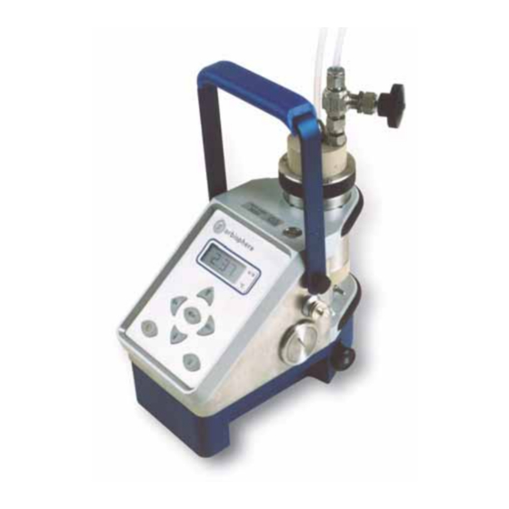
Section 3 Installation This section provides necessary information to set up the instrument. If you have any questions or experience any difficulties, do not hesitate to contact your Hach Lange representative regarding this procedure. 3.1 What you have received The ORBISPHERE 3654 portable analyzer includes the following major components: An instrument, model 3654/xxx, with keypad, display, and handle. -
Page 14: Atmospheric Pressure Equilibrium
Installation 3.3 Atmospheric pressure equilibrium As soon as you receive the instrument, it will be necessary to ensure the interior and exterior of the instrument are both at the same atmospheric pressure. It is probable that during shipment these pressures will become different. To ensure the pressures are equal, simply press the relief valve switch located on the top of the instrument (see Figure 1 on page... -
Page 15: Connections
Installation 3.6 Connections 3.6.1 External power supply (optional) The instrument is usually powered by the batteries supplied. You can, however, power it from an external power source using the model 32939 power supply adaptor as described and illustrated Model 32939 external power supply on page Connect the male LEMO-6 plug on the 32939, to the RS-232 connector on the right side of the instrument. -
Page 16: Flow Chamber Installation
Installation 3.7 Flow chamber installation The model 32013A or 32015 flow chamber allows the liquid or gaseous sample past the TC and temperature sensors. The flow chamber attaches to the TC sensor with a threaded collar and is ∅ ∅ sealed to the sensor with two O-rings (EPDM 20x2 mm and NBR 4x1.5 mm). -
Page 17: Installation Completion Check List
Installation 3.8 Installation completion check list 3.8.1 Power The instrument is designed to work on battery power or an external power supply. If battery power should drop, a [LO BAT] warning appears in the instrument LCD's top left corner, and they should be replaced. - Page 18 Installation...
-
Page 19: Section 4 Operating Instructions
Section 4 Operating Instructions 4.1 Operating controls The front panel of the instrument has a three-digit liquid crystal display (LCD). The LCD includes a right-side marker to distinguish between gas concentration and temperature display. This marker also indicates the measurement display units (g/kg, V/V, etc.) depending on the instrument configuration. -
Page 20: Taking Measurements
Operating Instructions Toggles between gas concentration and temperature measurement displays in measurement mode, increases or decreases the storage number during storage or memory view, or sets a calibration value during calibration You can access other instrument functions by pushing one of the following keys while also pressing the power button: Selects dissolved or gaseous measurement phase - see measurement phase on page 29... -
Page 21: Select Gas Measurement Phase
Operating Instructions Minimum sample flow rates, measurement ranges and response times for the various membranes are given in the tables in Sensor specifications on page The LCD includes a right-side marker to distinguish between gas concentration measurements and temperature. This marker also indicates the measurement display units (k/kg, V/V, etc. depending on the instrument configuration). -
Page 22: Automatic Data Acquisition
Operating Instructions 4.3.1 Automatic data acquisition Note: When the instrument is used to automatically store measurement data, all buttons except the key are disabled. If enough time elapses to store all 500 values, the instrument will return to POWER normal measurement mode and the buttons re-enabled. Before starting automatic measurement storage, first select the sampling rate desired using the WIN3654 program (see Automatic data acquisition - setting sampling intervals on page... -
Page 23: Manual Data Acquisition
Operating Instructions 4.3.2 Manual data acquisition Note: You cannot store measurement data manually if the instrument has already been set up to store the data automatically. 1. For the first measurement you wish to store, press the button once to display a sample number. -
Page 24: Viewing Stored Measurements
Operating Instructions 4.3.3 Viewing stored measurements 1. Put the instrument into standby (by pressing the key) POWER 2. Hold down the button while Up Arrow switching the instrument back ON. The LCD displays a sample location number. 3. Scroll through the numbered sample locations of all the stored values using the buttons. -
Page 25: Altering The Sampling Point Descriptions
Operating Instructions 4.4.2 Altering the sampling point descriptions For help in identifying the locations of various sampling points that are stored by the analyzer, you may choose the Sampling Point Description command from the Logger menu to bring up the dialog box illustrated in Figure Figure 6 Sampling point descriptions The measurement values to be placed in positions 0 through 499 (identified as Text 0, Text 1... -
Page 26: Clearing Stored Values
Operating Instructions 4.4.6 Clearing stored values To clear all the values stored in the analyzer via the WIN3654 program, choose the Clear Data command from the Logger menu. Since this action will clear the storage memory of the instrument, a warning appears first as shown left in Figure Figure 7 Clear stored values Choose OK to bring up the next dialog box to confirm the clear action. -
Page 27: After Use And Storage
Operating Instructions Click the TIMEBASE up/down pointers to change the time scale of the divisions of the chart. Each division mark along the baseline (1, 2, ...10) can be made to represent from 30 seconds to 2½ hours, providing from 5 minutes to 25 hours of continuously displayed samples. The chart updating rate is determined by the time scale selected, as shown in Table 3 below. - Page 28 Operating Instructions...
-
Page 29: Section 5 Options Setup
Section 5 Options Setup The WIN3654 program is an integral part of the analyzer. Running under Microsoft Windows®, it permits you to list and analyze up to 500 stored measurement values. The program also includes a special monitoring feature, which lets your computer act as a chart recorder, and enables a hardware test to ensure that the system is in good working order. - Page 30 Options Setup The Monitoring menu creates a running chart of real-time measurements (see Monitoring measurements in real-time on page 24). These values can also be saved to the Windows Clipboard. The Configuration menu lets you see how your system has been configured for your application.
-
Page 31: Analyzer - Pc Connection
Lange representative. 5.4 Configuring the instrument The ORBISPHERE 3654 analyzer can be readily configured for your application using the following commands in the Configuration menu. The instrument must be connected to your PC and powered on, in order to change any configuration parameters. -
Page 32: Measurement Units
Options Setup The gas measurement phase can also be selected from the instrument keyboard as follows: 1. Switch the instrument power 2. Switch the instrument on by holding down the button and then pressing the button while still pressing POWER button 3. -
Page 33: Membrane Selection
Note: You can create a solution having a known H or N concentration by dissolving H or N in water at a measured temperature and pressure. Hach Lange can provide equipment for generating such a solution. Alternatively, you can analyze a carbonated beverage independently by other acceptable means. -
Page 34: Locking Out The Instrument's Cal Button
Options Setup 5.4.6 Locking out the instrument’s CAL button You can use the Configuration, Sensor Calibration Status menu to prevent an accidental sensor re-calibration from the instrument keyboard. Choose Disabled to lock out the keyboard button. To unlock this capability, choose Enabled. Choose OK when the desired mode is selected. -
Page 35: Section 6 Calibrations
Section 6 Calibrations 6.1 Barometric pressure sensor calibration You must have access to an accurate barometer to calibrate the instrument's internal barometric pressure sensor. This is done using the PC WIN3654 program. Choose Troubleshooting, Pressure Calibration and a message will warn that the current calibration will be lost. -
Page 36: Calibration Setup
Calibrations Ensure that normal measurement mode is selected in the Measurement Mode menu of the WIN3654 program (see Measurement mode on page 32). Calibration must only be carried out once the TC sensor is giving a stable measurement. Expose the membrane to the calibration sample until this stable reading is obtained. This usually takes about 5 minutes. -
Page 37: Calibration In H Or N At Atmospheric Pressure
Calibrations 6.2.2 Calibration in H or N at atmospheric pressure The sensor can be calibrated in pure H or N gas at atmospheric pressure. WARNING Handle H gas with great care. It is extremely flammable and explosive. To ensure that the flow chamber and sensor components are dry, remove and blow dry the flow chamber. -
Page 38: Calibration In H Or N At Elevated Pressure
Calibrations 6.2.3 Calibration in H or N at elevated pressure The sensor can be calibrated in pure H or N gas at an elevated pressure. This method requires an accurate pressure gauge connected to the exit of the flow chamber. WARNING Handle H gas with great care. -
Page 39: Calibrating In A Liquid H Or N Solution
Calibrations 6.2.4 Calibrating in a liquid H or N solution The sensor can be calibrated in a standard liquid solution that has a known concentration of H or N You can create a solution with a known concentration by dissolving H or N in water at a measured temperature and pressure. - Page 40 Calibrations...
-
Page 41: Section 7 Accessories And Attachments
Section 7 Accessories and Attachments 7.1 Model 32311 flow meter A flow meter is available as an option, to attach to the top of the flow chamber, instead of the flow rate adjustment valve usually supplied. This can be used to set an accurate flow rate of the sample. - Page 42 Accessories and Attachments...
-
Page 43: Section 8 Maintenance And Troubleshooting
The membrane needs to be replaced once or twice a year depending on application conditions. This can be tailored accordingly. Note: If you are not familiar with ORBISPHERE sensor servicing, your Hach Lange representative will be glad to assist you. -
Page 44: Testing The Sensor Condition
Maintenance and Troubleshooting 8.2.3 Testing the sensor condition Periodically, visually inspect the sensor head for any deposits. Rinse it under clean tap water, and dry with a clean tissue. To verify the sensor, check measurements vs. a known standard sample value: If reading deviation is ±1% of the expected value, no action needs to be taken. -
Page 45: Installing The Membrane
Maintenance and Troubleshooting 8.3.2 Installing the membrane To install the new membrane, follow the steps below: Note: The membrane mounting surface must be clean and even (on top of the sensor, where the membrane and sensor have contact). Replace the membrane O-ring on the sensor head with a new one. - Page 46 Maintenance and Troubleshooting Note: Distinguish the membrane from the protection paper: - Membrane is transparent (translucent). - Protection paper is opaque. The membrane diameter is larger than the sensor head diameter. This is normal, as the membrane will fold over the sensor tip.
-
Page 47: Purge Gas Cylinder Refill
Maintenance and Troubleshooting Finally replace the flow chamber. Gently lower the flow chamber onto the sensor, guiding the thermistor on the sensor into the hole in the flow chamber base. Turn the flow chamber locking pin (see Figure 1 on page clockwise to secure it in place. -
Page 48: N 2 Purge Gas
Maintenance and Troubleshooting 8.4.1 N Purge gas Fill the N purge gas cylinder to a maximum of 200 bar from a master N storage cylinder, using fittings supplied with the analyzer. CAUTION Although N is not toxic, it is asphyxiating. Therefore, filling should be carried out in a ventilated place and leaks should be avoided. -
Page 49: Troubleshooting - Instrument
Maintenance and Troubleshooting 8.5 Troubleshooting - instrument If your analyzer is behaving strangely (failing to calibrate, giving inappropriate measurement values, etc.) and you have attempted to rectify the problem by servicing the sensor (for instructions, see Sensor maintenance on page 41) but to no avail, you may wish to use the WIN3654 Troubleshooting menu to make sure that the instrument is configured correctly for your application, and is in good working order. -
Page 50: Clock Settings
The Troubleshooting, Analog Voltage View gives a real-time look at voltages used by the system to transmit information about gas, temperature and pressure. This is useful when trying to identify an instrument problem with a Hach Lange service representative either on-site or over the phone. -
Page 51: Measurements View
In case of problems, it may be necessary to check the current version of your software as this may be required by Hach Lange if you need to contact them for assistance in problem solving. To identify the version of the software in your instrument, switch off the instrument. Then hold down the button while switching the instrument back on. -
Page 52: Troubleshooting Table
If the solenoid leaks Leaking solenoid valve (more than 1 bubble in 15 seconds) contact your Hach Lange representative. An external power supply is used but the Switch to battery power power supply is not clean... -
Page 53: Section 9 Part Lists
Section 9 Part Lists 9.1 Instrument configurations Table 7 Instrument configurations Description Instrument Instrument Portable battery powered, RS232 (serial) output. 3654/210 For use with sensor 31270. Portable battery powered, RS232 (serial) output. 3654/211 For use with sensor 31272. Special sensor purge: Carbon dioxide. Portable battery powered, RS232 (serial) output. -
Page 54: Analyzer Spare Parts
Part Lists 9.3 Analyzer spare parts Table 9 Analyzer spare parts Part N° Description 28083 Connector LEMO 6, male. TC Sensor, Substance measured: Hydrogen, Purge gas: Nitrogen, Protection cap 31270 provided, Maximum pressure: 10 bar, External Temperature Sensor Included. TC Sensor, Substance measured: Hydrogen, Purge gas: Carbon dioxide, Protection 31272 cap provided, Maximum pressure: 10 bar, External Temperature Sensor Included. -
Page 55: Section 10 Glossary Of Terms
Section 10 Glossary of Terms 10.1 Common units Table 11 Common units Unit Meaning percentage, by weight % vbar percentage per volume, barometric pressure referenced % vext percentage per volume, sample pressure compensated cc/kg cubic centimeters per kilogram g/kg grams per kilogram mg/L milligrams per liter mL/L... - Page 56 Glossary of Terms...
Need help?
Do you have a question about the ORBISPHERE 3654 and is the answer not in the manual?
Questions and answers