
Related Manuals for HACH LANGE 9185sc


Summary of Contents for HACH LANGE 9185sc
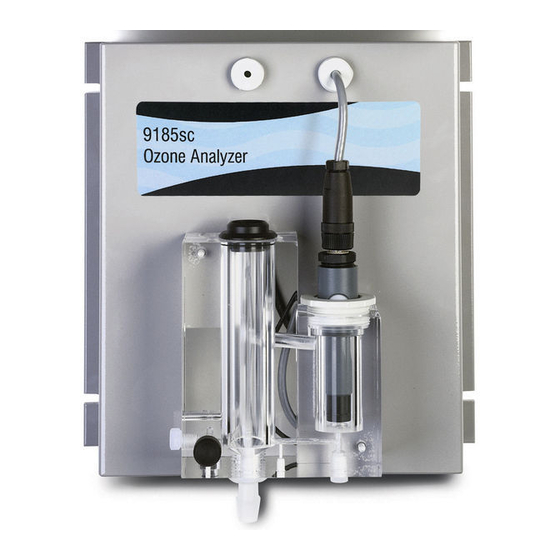
- Page 1 DOC023.52.00051 9184sc Chlorine 9185sc Ozone and 9187sc Chlorine Dioxide Analyzer USER MANUAL 02/2013 Edition 2A...
- Page 2 © HACH LANGE GmbH, 2005, 2013. All rights reserved. Printed in Germany.
-
Page 3: Table Of Contents
Table of Contents Section 1 Specifications ............................3 Section 2 General Information ..........................5 2.1 Safety Information ............................... 5 2.1.1 Use of Hazard Information ......................... 5 2.1.2 Precautionary Labels ..........................5 2.2 General Sensor Information ..........................6 2.3 Theory of Operation............................. 6 Section 3 Installation...............................9 3.1 Mounting the Analyzer............................9 3.1.1 Environmental Considerations ........................ - Page 4 Appendix A 9184sc Theory of Operation......................37 A.1 Theory of Operation ........................... 37 A.1.1 Principle of Operation ........................37 Appendix B 9185sc Theory of Operation......................39 B.1 Theory of Operation ........................... 39 B.1.1 Principle of Operation ........................39 Appendix C 9187sc Theory of Operation......................41 C.1 Theory of Operation ...........................
-
Page 5: Section 1 Specifications
Application Sample Clean water Electrical Power Consumption 12 V, 1.5 Watts provided by sc controller Performance 9184sc 9185sc 9187sc Measurement Range 0–20 ppm (0–20 mg/L) HOCl 0–2 ppm (0–2 mg/L) O 0–2 ppm (0–2 mg/L) ClO Detection Limit 5 ppb (0.005 mg/L) HOCl 5 ppb (0.005 mg/L) O... -
Page 6: Specifications
Operating Temperature Range 0 to 45 °C (32 to 113 °F) Relative Humidity 10 to 90% non-condensing Operating Humidity 0 to 90% non-condensing Compliance The sc analyzer and sensor combination are: CE marked and declared by HACH LANGE to the applicable EU Safety and EMC Directives. -
Page 7: Section 2 General Information
Section 2 General Information 2.1 Safety Information Please read this entire manual before unpacking, setting up, or operating this equipment. Pay attention to all danger and caution statements. Failure to do so could result in serious injury to the operator or damage to the equipment. To ensure that the protection provided by this equipment is not impaired, do not use or install this equipment in any manner other than that specified in this manual. -
Page 8: General Sensor Information
The choice can be made to use this instrument with the specifications and processes of the 9184sc, 9185sc, or 9187sc sensor. This is determined by selecting the parameter during the initial sensor setup and the type of sensor being used. See 4.3 Sensor Setup... -
Page 9: General Information
General Information Figure 2 General Instrument Schematic** pH Probe (9184sc only) Gateway (behind Mounting Plate) pH Cell Cap (9184sc only) Connector Connector Cell Cap Cable to Controller Probe Body **See Replacement Parts and Accessories on page... - Page 10 General Information...
-
Page 11: Section 3 Installation
Section 3 Installation DANGER Only qualified personnel should conduct the tasks described in this section of the manual. 3.1 Mounting the Analyzer The analyzer is designed to be mounted on a flat, vertical surface such as a wall, panel, stand, etc. The instrument must be level. Locate the sensor as close to the sampling point as possible. -
Page 12: General Installation Considerations
Installation 3.1.2 General Installation Considerations • Place the analyzer in an accessible location. • Keep the sample tubing as short as possible to minimize lag time. • Do not place the probe next to a heat source. • Ensure that there is no air intrusion into the sample supply line. •... -
Page 13: Connecting The Waste Stream
Installation 3.4 Connecting the Waste Stream Connect the waste stream using the supplied ½-inch ID tubing. Be sure the drain is free flowing (free of obstructions) so that the waste stream does not cause unnecessary back-pressure or overflow. Note: Waste from this instrument must go to the drain. 3.5 Assembling and Placing the Probe Refer to Figure 5... - Page 14 Installation 6. Tap the side of the probe to make sure that no air bubbles are trapped in the probe body when inserting the electrode. 7. Screw on the retaining ring. Some electrolyte may spill out the top of the body. 8.
-
Page 15: Placing The Probe Into The Flow Thru Assembly
Installation Figure 7 Tightening the Membrane Displays the correct way to tighten the membrane. It is Displays the incorrect way to tighten the membrane. It is snug but not overtightened. too loose and the internal electrolyte could leak. 3.5.1.1 Placing the Probe Into the Flow Thru Assembly 1. - Page 16 Installation Figure 8 Placing the Probe Into the Flow Thru Assembly** Electrode Cable Connector Probe Assembly Probe Retaining Nut Flow Thru Assembly **See Replacement Parts and Accessories on page...
-
Page 17: Using The Optional Ph (9184Sc Tfc Only)
Installation 3.5.1.2 Using the Optional pH (9184sc TFC only) The optional pH (Figure 2 on page 7) is used when analysis is needed for measuring all of – the free available chlorine (both HOCI and OCI ). See 4.3 Sensor Setup on page 19 selecting this option using the controller during initial sensor parameter selection. -
Page 18: Instrument And Controller Startup
Installation Figure 10 Quick-connect Fitting pin assignment Number Designation Wire Color +12 VDC Brown Circuit Common Black Data (+) Blue Data (–) White Shield Shield (grey wire in existing quick-disconnect fitting) Groove 3.7 Instrument and Controller Startup 1. Ensure the flow regulator is threaded (clockwise) all the way and is snug but not overtightened. - Page 19 Installation Figure 11 Setting the Flow Rate Sample inlet tubing Sample Flow meter adjustment knob Drain tubing Sample level overflow (indicates the correct water level)
- Page 20 Installation...
-
Page 21: Section 4 Operation
Section 4 Operation 4.1 Using the sc Controller Before using the sensor in combination with an sc controller make yourself familiar with the operating mode of the controller. Refer to the controller user manual and learn how to use and navigate the menu functions. 4.2 Sensor Data Logging The sc controller provides one data log and one event log for each sensor. -
Page 22: Sensor Diagnostics Menu
Operation 4.4 Sensor Diagnostics Menu SELECT SENSOR ERROR LIST—See section 6.1 on page WARNING LIST— See section 6.2 on page 4.5 Sensor Setup Menu SELECT SENSOR (if more than one sensor is attached) CALIBRATE ZERO CAL section 4.6.4 on page PROCEESS CONC Use to adjust concentration which requires accurate pH;... -
Page 23: Calibration
Operation 4.5 Sensor Setup Menu (continued) DISP PH FORMAT (9184sc T.F.C or 9184sc Chlorine + Acid only) Choose either XX.XX pH or XX.X pH. pH MAXIMUM (9184sc T.F.C only) Allows user to set the maximum pH allowed value. An higher value will display a PH TOO HIGH error message. LOG SETUP Allows user to select data logging interval for the sensor and temperature. -
Page 24: Adjusting The Temperature
Operation Temperature Conversion Conversion from Celsius to Fahrenheit: °F = 1.8 x °C + 32 Conversion from Celsius to Kelvin: K = °C + 273.15 Table 1 Temperature Conversions °C °F °C °F °C °F 273.15 60.8 289.15 89.6 305.15 33.8 274.15 62.6... -
Page 25: Process Ph 2 Point Sample
(Cat. No. 5870023) for all other 9184sc uses. 9185sc To test for Ozone, use the Indigo Method, Ozone HR AccuVac test (Cat. No. 25180-25) that goes with the DR/4000, DR/2500, DR/890, and the Pocket Colorimeter II. -
Page 26: Process Calibration
Operation 9187sc To test for Chlorine Dioxide use the DPD Glycine Method, Chlorine Dioxide Reagent Set (Cat. No. 27709-00) that goes with the DR/4000, DR/2500, and DR/890, and Pocket Colorimeter II. Note: Please reference the manufacturer catalog for other methods. When performing the following steps, calculate the pH first then write down that number for reference. -
Page 27: Chemical Zero Calibration
Operation 4.6.4.1 Chemical Zero Calibration 1. From the Main Menu, select SENSOR SETUP and confirm. 2. Highlight the appropriate sensor if more than one is attached and confirm. 3. Select CALIBRATE and confirm. 4. Select ZERO and select the available Output Mode (Active, Hold, or Transfer) from the list box and confirm. - Page 28 Operation...
-
Page 29: Section 5 Maintenance
Section 5 Maintenance DANGER Only qualified personnel should conduct the tasks described in this section of the manual. 5.1 Maintenance Schedule The following schedule shows the minimum maintenance requirements for typical operation. Maintenance Task 2 Months 3 Months 6 Months Annually Membrane Electrolyte... -
Page 30: Replacing The Tubing
Maintenance Figure 12 Disassembling the Sensor Probe Chamber Measurement Electrode Probe Assembly Probe Body Probe Retaining Nut Filling Screw Electrode Cable Connector Probe Body Washer Electrode Retaining Ring 10. Pre-mounted Membrane 5.2.2 Replacing the Tubing Replace the tubing annually, if necessary. 5.2.3 Replacing the Electrolyte Replace the electrolyte when changing the membrane. -
Page 31: Section 6 Troubleshooting
Section 6 Troubleshooting 6.1 Error Messages Note: When an error occurs, the measurement values are replaced by dashes, (- - -). Message Type Error Message Solution Check the current value, along with the calibration parameters. Check CONC TOO HIGH electrode. Check the current value, along with the calibration parameters. - Page 32 Troubleshooting...
-
Page 33: Section 7 Replacement Parts And Accessories
7.2 Replacement Parts Description Catalog Number pH Electrode 368416,00000 9184sc set of 4 pre-mounted membranes 09184=A=3500 9185sc set of 4 pre-mounted membranes 09185=A=3500 9187sc set of 4 pre-mounted membranes 09187=A=3500 Electrolyte for the 9184sc 09184=A=3600 Electrolyte for the 9185sc 09185=A=3600... -
Page 34: Extension Cables
Replacement Parts and Accessories 7.4 Extension Cables Description Catalog Number Cable, sensor extension, 0,35 m LZX847 Cable, sensor extension, 5 m LZX848 Cable, sensor extension, 10 m LZX849 Cable, sensor extension, 15 m LZX850 Cable, sensor extension, 20 m LZX851 Cable, sensor extension, 30 m LZX852... -
Page 35: Section 8 Contact
Fax +34 94 657 33 97 www.hach-lange.dk www.hach-lange.se www.hach-lange.it info@hach-lange.es www.hach-lange.es HACH LANGE LDA HACH LANGE SP. ZO.O. HACH LANGE S.R.O. HACH LANGE S.R.O. Av. do Forte nº8 ul. Krakowska 119 Zastrčená 1278/8 Roľnícka 21 Fracção M PL-50-428 Wrocław CZ-141 00 Praha 4 - Chodov SK-831 07 Bratislava –... - Page 36 Contact HACH LANGE D.O.O. ΗΑCH LANGE E.Π.Ε. HACH LANGE D.O.O. HACH LANGE MAROC SARLAU Fajfarjeva 15 Αυλίδος 27 Ivana Severa bb SI-1230 Domžale GR-115 27 Αθήνα HR-42 000 Varaždin Villa 14 – Rue 2 Casa Tel. +386 (0)59 051 000 Τηλ.
-
Page 37: Section 9 Warranty, Liability And Complaints
Section 9 Warranty, liability and complaints HACH LANGE GmbH warrants that the product supplied is free of material and manufacturing defects and undertakes the obligation to repair or replace any defective parts at zero cost. The warranty period for instruments is 24 months. If a service contract is taken out within 6 months of purchase, the warranty period is extended to 60 months. - Page 38 Warranty, liability and complaints...
-
Page 39: Appendix A 9184Sc Theory Of Operation
Appendix A 9184sc Theory of Operation A.1 Theory of Operation The 9184sc Chlorine Analyzer is an on-line, single-channel industrial analyzer that measures free chlorine in drinking water treatment plants, distribution networks, and other applications that require monitoring free chlorine at the ppb and ppm levels. This instrument uses an amperometric method to measure HOCl concentration. - Page 40 9184sc Theory of Operation It is also important to notice that the dissociation constants are temperature-dependent (the equipment takes into account this element). The amperometric sensor consists of: • a gold working electrode (cathode) where the main reaction occurs • a silver counter-reference electrode (anode) •...
-
Page 41: Appendix B 9185Sc Theory Of Operation
Appendix B 9185sc Theory of Operation B.1 Theory of Operation The 9185sc Ozone Analyzer is an on-line, single-channel industrial analyzer that measures ozone in drinking water treatment plants, distribution networks, and other applications that require monitoring ozone at the ppb and ppm levels. - Page 42 9185sc Theory of Operation...
-
Page 43: Appendix C 9187Sc Theory Of Operation
Appendix C 9187sc Theory of Operation C.1 Theory of Operation The 9187sc Chlorine Dioxide Analyzer is an on-line, single-channel industrial analyzer that measures chlorine dioxide in drinking water treatment plants, distribution networks, and other applications that require monitoring chlorine dioxide at the ppb and ppm levels. This instrument uses an amperometric method to measure chlorine dioxide concentration. - Page 44 9187sc Theory of Operation...
-
Page 45: Appendix D Modbus Register Information
Appendix D Modbus Register Information Table 2 Sensor Modbus Registers Tag Name Register # Data Type Length Description Main Measurement Parameter in Concentration Measurement Tag in 40001 Float mg/L mg/L pH Measurement Param. 40003 Float pH Measurement Tag Temperature measurement 40005 Float Temperature measurement... - Page 46 Modbus Register Information Table 2 Sensor Modbus Registers (continued) Tag Name Register # Data Type Length Description 40047 Integer Internal use 40048 Integer Internal use Averaging 40049 Integer Averaging Automatic/Manual temperature 40050 Automatic/Manual temperature toogle toogle Manual Temperature unit 40051 Integer Manual Temperature unit Manual Temperature...
- Page 47 Modbus Register Information Table 2 Sensor Modbus Registers (continued) Tag Name Register # Data Type Length Description DriverVersion_float 40104 Float Driver version 40106 Float Internal use Measurement Logging Interval 40108 Integer Sensor Data logging interval Temperature Logging Interval 40109 Integer Temperature logging interval...
- Page 48 Modbus Register Information...
- Page 49 Safety ................5 Sample Line ..............10 sc100 Warning Messages ..........29 Sensor Instrument Specifications ..........3 Data Logging ............19 Sensor Cable Wiring..............16 Mounting Installation Considerations ........10 Theory 9184sc.............. 37 Theory 9185sc.............. 39 Optional pH..............15 Theory 9187sc.............. 41...
- Page 50 Index...
Need help?
Do you have a question about the 9185sc and is the answer not in the manual?
Questions and answers