Table of Contents
Advertisement
Quick Links
Advertisement
Table of Contents
Troubleshooting

Related Manuals for Bovie AARON 2250

Summary of Contents for Bovie AARON 2250
- Page 1 SERVICE GUIDE Ser vice Guide • Aaron 2250...
-
Page 2: Equipment Covered In This Manual
(with chart comparisons). The Aaron 2250 was constructed with the highest quality components, and was built in an ISO 9001 registered environment. In the unlikely event that your generator fails within one year of purchase date, Aaron Medical will warranty the product and effect factory repairs. -
Page 3: Safety Precautions When Operating The Generator
There is no substitute for a properly trained and vigilant medical staff. It is important that they read, understand, and follow the operating instructions supplied with this electrosurgical equipment. To promote the safe use of the Aaron 2250, please refer to the User’s Guide for standard operating precautions. APPLICABLE SAFETY STANDARDS CSA C22.2, NO. -
Page 4: Table Of Contents
Equipment Covered in this Manual................ii For Information Contact ....................ii Safety Precautions When Operating the Generator ............iii Applicable Safety Standards....................iii Conventions Used in this Guide..................iii The Aaron 2250........................1-1 Functional Description.....................1-2 Unit Description .......................1-3 Safety Precautions When Repairing the Generator............1-3 General Warnings, Cautions, and Notices ..............1-3 Active Accessories....................1-4... - Page 5 RF Drive .........................4-4 HV Relay .........................4-4 Output........................4-4 Sense and Backup Sense Circuits................4-4 Controls and Indicators ....................4-5 Aaron 2250 Control Signal Inputs and Outputs ..............4-5 Operating the Aaron 2250 ....................5-1 Inspecting the Generator and Accessories ..............5-2 Service Personnel Safety....................5-2 Installation and Placement ....................5-3 Functional (Operational) Checks..................5-3...
- Page 6 Figure 3 – 17 Bipolar set to 80 W, at no load ..............3-14 Figure 3 – 18 Bipolar set to 80 W, actual power set to 200 W load ........3-14 Figure 4 – 1 Functional Block Diagram of the Aaron 2250 system........4-2 Figure 6 – 1 Fuse holder......................6-2 Figure 6 –...
- Page 7 Silkscreen for Bottom of Display PCB for Component Locations.........B-28 Silkscreen for Relay PCB for Component Locations............B-29 Final Assembly Overview......................B-30 Cabling in Assembly ......................B-31 Mechanical Front Panel Assembly..................B-32 Mechanical Back Panel Assembly..................B-33 Cabling Back Panel Assembly....................B-34 Ser vice Guide • Aaron 2250...
- Page 8 viii Aaron Medical...
-
Page 9: The Aaron 2250
Safety Precautions when Repairing the Generator CAUTIONS: Read all warnings, cautions, and instructions provided with this generator before using. Read the instructions, warnings, and cautions provided with electrosurgical accessories before using. Specific instructions are not included in this manual. Ser vice Guide • Aaron 2250... -
Page 10: Functional Description
FUNCTIONAL DESCRIPTION The Aaron 2250 is a multipurpose electrosurgical generator for use in physician’s offices and surgi-centers. This unit offers unsurpassed performance, flexibility, reliability, and user convenience. The Aaron 2250 includes digital technology. This new technology is evident in the self-checking circuitry and error code readouts. -
Page 11: Unit Description
These diagnostics continually monitor the unit to ensure proper performance. UNIT DESCRIPTION The Aaron 2250 is a self-contained unit, consisting of the main enclosure and power cord. The main components incorporated in the generator include: • Front Panel Components Power switch; membrane switches to control power output and mode selection;... -
Page 12: Active Accessories
Active Accessories WARNINGS: Shock Hazard - Do not connect wet accessories to the generator. Shock Hazard - Ensure that all accessories and adapters are correctly connected and that no metal is exposed. CAUTIONS: Accessories must be connected to the proper receptacle type. In particular, bipolar accessories must be connected to the Bipolar Instrument receptacle only. -
Page 13: Generator Electric Shock Hazards
Use an anti-static container for transport of electrostatic-sensitive components and circuit boards. Cleaning NOTICE: Do not clean the generator with abrasive cleaning or disinfectant compounds, solvents, or other materials that could scratch the panels or damage the generator. Ser vice Guide • Aaron 2250... - Page 14 Aaron Medical...
-
Page 15: Controls, Indicators, And Receptacles
CONTROLS, INDICATORS, AND RECEPTACLES This section describes: ● ● The Front Panel ● ● Controls and Indicators Overview ● ● The Rear Panel Ser vice Guide • Aaron 2250... -
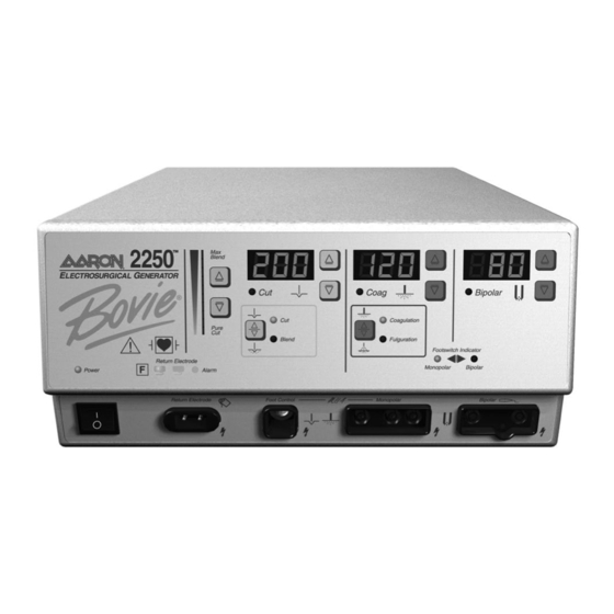
Page 16: Front Panel
FRONT PANEL Figure 2 – 1 Layout of controls, indicators, and receptacles on the front panel Aaron Medical... -
Page 17: Controls And Indicators Overview
CONTROLS AND INDICATORS OVERVIEW Users may control most Aaron 2250 functions from the front panel. Each control is plainly marked and colored on the front panel for quick reference. The volume control is located on the rear panel. Normal operations involve activating the generator with either a front connected handswitch or footswitch. -
Page 18: Symbols On The Front Panel
Symbols on the Front Panel SYMBOLS DESCRIPTION Cut Controls Cut Mode Blend Mode Coag Controls Coagulation Mode Fulguration Mode Bipolar Controls Bipolar Mode Indicators Split Return Electrode Solid Return Electrode Regulatory Symbology Read instructions before use. Defibrillator proof type CF equipment RF Isolated –... -
Page 19: Cut And Blend Controls
10 steps. Indicates when the Blend Cut and Blend mode is selected. modes. NOTICE: When selecting the Blend mode, the unit defaults to a setting of minimum blend (only the first bar is illuminated). Ser vice Guide • Aaron 2250... -
Page 20: Coag Controls
Coag Controls Figure 2 – 3 Controls for the Coag mode Coag Power Control Buttons Coag Power Display (watts) Increases or decreases the Coagulation Indicates the power set for or Fulguration Coag power output in the Coag mode. increments of 1 to 10 watts. Coag Activation Indicator Illuminates when Coag mode is activated. -
Page 21: Bipolar Controls
Bipolar Power Control Buttons Displays error code in the event Increases or decreases the Bipolar power of an error. output in increments of 1 to 10 watts. Bipolar Activation Indicator Illuminates when Bipolar mode is activated. Ser vice Guide • Aaron 2250... -
Page 22: Indicators
Indicators Figure 2 – 5 Indicators for power, return electrodes, and footswitch control Monopolar Footswitch Indicator Bipolar Footswitch Indicator Illuminates when monopolar Illuminates when bipolar footswitch control is plugged footswitch control is plugged in in and available. and available. Power Indicator Illuminates when the Split Return Solid Return... -
Page 23: Power Switch And Receptacles
Monopolar Footswitching Receptacle Bipolar Receptacle Turns the unit on or off. Accepts cables or adapters equipped Accepts standard cables for with standard (Aaron #12) active plugs. bipolar handpieces. Connect Connect footswitching accessories. bipolar accessories. Ser vice Guide • Aaron 2250... -
Page 24: Rear Panel
REAR PANEL Figure 2 – 7 Layout of connectors and controls on the rear panel Symbols on the Rear Panel SYMBOLS DESCRIPTION Equipotential Ground Stud Non-ionizing Radiation Volume Control Danger - Explosion Risk If Used With Flammable Anesthetics. Fuse Enclosed Relay Connector Monopolar Footswitch Input Jack Bipolar Footswitch Input Jack... -
Page 25: Technical Specifications
All specifications are nominal and subject to change without notice. A specification referred to as “typical” is within ± 20% of a stated value at room temperature (25° C / 77° F) and a nominal input power voltage. Ser vice Guide • Aaron 2250... -
Page 26: Performance Characteristics
PERFORMANCE CHARACTERISTICS Input Power Input Voltage 100-240 VAC Mains line frequency range (nominal): 50 / 60 Hz Power consumption: 500 VA Fuses (two): 6.3 A (slow blow) Duty Cycle Under maximum power settings and rated load conditions (Cut, 200 watt @ 300 ohm load), the generator is suitable for activation times of 10 seconds ON followed by 30 seconds OFF for one hour. -
Page 27: Audio Volume
Normal polarity, intact ground: < 10 µA Source current, patient leads, all outputs Normal polarity, ground open: < 10 µA Reverse polarity, ground open: < 10 µA Sink current at high line, all inputs < 10 µA Ser vice Guide • Aaron 2250... -
Page 28: High Frequency (Rf) Leakage Current
The Aaron 2250 complies with the appropriate IEC 60601-1-2 and IEC 60601-2-2 specifications regarding electromagnetic compatibility. Voltage Transients (Emergency Generator Mains Transfer) The Aaron 2250 operates in a safe manner when the transfer is made between line AC and an emergency generator voltage source. Aaron Medical... -
Page 29: Output Characteristics
490 kHz ± 5 kHz 30 kHz ± 5 kHz 7000 V 6.5 ± 20% Bipolar 80 W @ 150 Ω 490 kHz ± 5 kHz 30 kHz ± 5 kHz 1000 V 1.6 ± 20% Ser vice Guide • Aaron 2250... -
Page 30: Output Power Curves
Output Power Curves The curves that follow depict the changes for each mode at specific power settings. Figure 3 – 1 Output power vs impedance for Cut mode Figure 3 – 2 Output power versus impedance for Blend mode, set at Minimum. Aaron Medical... -
Page 31: Figure 3 - 3 Output Power Versus Impedance For Blend Mode, Set At Maximum
Figure 3 – 3 Output power versus impedance for Blend mode, set at Maximum Figure 3 – 4 Output power vs impedance for Coagulation mode Coagulation Ser vice Guide • Aaron 2250... -
Page 32: Figure 3 - 5 Output Power Vs Impedance For Fulguration Mode
Figure 3 – 5 Output power vs impedance for Fulguration mode Fulguration Figure 3 – 6 Output power vs impedance for Bipolar mode Aaron Medical... -
Page 33: Output Waveforms
The following figures are the output waveforms as viewed on an oscilloscope. Figure 3 – 7 Cut set to 200 W, at no load, open Figure 3 – 8 Cut set to 200 W, actual power 200 W at 300 ohm load Ser vice Guide • Aaron 2250... -
Page 34: Figure 3 - 9 Blend Minimum Set To 200 W, At No Load, Open
Figure 3 – 9 Blend minimum set to 200 W, at no load, open Figure 3 – 10 Blend minimum set to 200 W, actual power 200 W at 300 ohm load 3-10 Aaron Medical... -
Page 35: Figure 3 - 11 Blend Maximum Set To 200 W, At No Load, Open
Figure 3 – 11 Blend maximum set to 200 W, at no load, open Figure 3 – 12 Blend maximum set to 200 W, actual power 200 W at 300 ohm load Ser vice Guide • Aaron 2250 3-11... -
Page 36: Figure 3 - 13 Coagulation Set To 120 W, At No Load, Open
Figure 3 – 13 Coagulation set to 120 W, at no load, open Figure 3 – 14 Coagulation set to 120 W, actual power 120 W at 500 ohm load 3-12 Aaron Medical... -
Page 37: Figure 3 - 15 Fulguration Set To 80 W, At No Load, Open
Figure 3 – 15 Fulguration set to 80 W, at no load, open Figure 3 – 16 Fulguration set to 80 W, actual power 80 W at 500 ohm load Ser vice Guide • Aaron 2250 3-13... -
Page 38: Figure 3 - 17 Bipolar Set To 80 W, At No Load
Figure 3 – 17 Bipolar set to 80 W, at no load Figure 3 – 18 Bipolar set to 80 W, actual power set to 200 W load 3-14 Aaron Medical... -
Page 39: Theory Of Operation
THEORY OF OPERATION This section contains the following information ● ● Block Diagram ● ● Functional Overview of Key Circuits ● ● Controls and Indicators ● ● Aaron 2250 Control Signal Inputs and Outputs Ser vice Guide • Aaron... -
Page 40: Block Diagram
Functional Block Diagram of the Aaron 2250 system. FUNCTIONAL OVERVIEW OF KEY CIRCUITS The following descriptions highlight the main circuits in the Aaron 2250. Controls and Indicators The front panel overlay contains 10 membrane function switches. Each membrane switch is used to toggle between modes, presets, and power settings. -
Page 41: Temperature Sensing Circuits (3)
RF output is disabled. Input Voltage The Aaron 2250 is designed to operate at a wide range of input voltages. The unit will perform with in specifications with an input voltage within the range of 100-240VAC 50/60 Hz. The input voltage is connected via a power entry module. -
Page 42: Control Circuit
PFC also regulates the universal input of 100 to 240 watt voltages that power the unit. Power Supply The Aaron 2250 incorporates a medically approved 40W Quad output power supply. +12VDC, 5VDC, -12VDC, 3.3VDC, and 5VDC are generated by this power supply. These voltages are used by the main and display board to supply power to all logic circuits. -
Page 43: Controls And Indicators
Voltage and current are sensed during power output. CONTROLS AND INDICATORS The Aaron 2250 controls and indicators are listed below: • MEMBRANE SWITCHES Toggle between modes. • DISPLAYS Three separate displays (Cut, Coag, & Bipolar) indicate the output power in watts. - Page 44 This is an input signal from the bipolar footswitch sense circuit. This signal is generated RQEST_SENSE_FOOT_ by a colpitts oscillator located on the display board and an isolation transformer located on BIPOLAR the main board. When an activation request is made, the output for this circuit becomes a logic 1 (3.3 volts) signal.
- Page 45 This is an output signal from the system logic to control the SMPS circuit. SMPS_DRV2 Used for controlling the voltage of the high voltage power supply, controls the output power. This is an output signal from the system logic to control the SMPS circuit. SMPS_DRV1 Used for controlling the voltage of the high voltage power supply, controls the output power.
- Page 46 This is and output signal from the system logic that generates a 62.5 kHz square wave. NEM_CLK_GEN This signal is used by the NEM circuit. This is an output signal from the system logic that controls an analog switched. This NEM_PAD_SENSE_EN signal is used by the NEM circuit to change the analog signal sent to the NEM A/D.
- Page 47 This is an input signal to the system logic from the front panel overlay to decrease the COAG_DOWN power setting for Coagulation and Fulguration coag modes. This is an input signal to the system logic from the front panel overlay to increase the COAG_UP power setting for Coagulation and Fulguration coag modes.
- Page 48 A/D1_REF_V_DAC_DATA This is a communication line used by the system logic to control the sensing A/D’s. A/D1_REF_V_DAC_SCLK This is a communication line used by the system logic to control the sensing A/D’s. A/D1_REF_V_DAC_SYNC This is a communication line used by the system logic to control the sensing A/D’s. A/D2_REF_V_DAC_DATA This is a communication line used by the system logic to control the sensing A/D’s.
-
Page 49: Operating The Aaron 2250
This section covers the following topics: ● ● Inspecting the Generator and Accessories ● ● Service Personnel Safety ● ● Installation and Placement ● ● Functional (operational) Checks ● ● Operating the Unit ● ● Activating the Unit Ser vice Guide • Aaron 2250... -
Page 50: Inspecting The Generator And Accessories
INSPECTING THE GENERATOR AND ACCESSORIES Before each use of the Aaron 2250, inspect the unit and all accessories to verify good working order: • Inspect for physical damage to the generator and its connections. • Verify that the appropriate accessories and adapters are present. -
Page 51: Installation And Placement
Note the error code and refer to Section 7, Troubleshooting. Once the self-test is successful, connect the accessories and set the generator controls. Refer to Preparing for Monopolar Surgery or Preparing for Bipolar Surgery later in this section. Ser vice Guide • Aaron 2250... -
Page 52: Preparing For Monopolar Surgery
(Bovie NEM™). NOTICE: The Bovie NEM™ system recommends that you use a split return electrode. Refer to the manufacturer’s instructions for application site and placement procedures. When using metal plate return electrodes, use a conductive gel specifically designed for electrosurgery. Select a return electrode site with good blood flow. -
Page 53: Activating The Unit
When you turn on your unit remember the following features: The Aaron 2250 will power up to the last used modes and last used settings. During activation, the activated mode can be adjusted up and or down a maximum of four steps. - Page 54 Aaron Medical...
-
Page 55: Maintaining The Aaron 2250
MAINTAINING THE AARON 2250 This section covers the following topics: ● ● Cleaning ● ● Periodic Inspection ● ● Fuse Replacement Ser vice Guide • Aaron 2250... -
Page 56: Cleaning
Do not allow fluids to enter the chassis. Do not sterilize the generator. PERIODIC INSPECTION Every six months, visually inspect the Aaron 2250 for signs of wear or damage. In particular, look for any of the following problems: • Damage to the power cord •... -
Page 57: Fuse Replacement On The Main Pcb
7. Replace and secure the cover panel. Figure 6 – 2 Fuse location Main PCB Fuse Information 250 VAC 250 VAC AMPS 6.3 A 0.5 A Size 5 x 20 mm 5 x 20 mm Type Slow Blow Slow Blow Ser vice Guide • Aaron 2250... - Page 58 Aaron Medical...
-
Page 59: Troubleshooting
TROUBLESHOOTING This section includes error code descriptions and actions to take to resolve them. Ser vice Guide • Aaron 2250... -
Page 60: Recommended Equipment For Troubleshooting
• If an error code was displayed, take the appropriate action(s) to correct the error condition. Inspecting the Generator If the Aaron 2250 malfunctions, check for obvious conditions that may have caused the problem. 1. Check the generator for visible signs of physical damage. -
Page 61: Inspecting Internal Components
5. Reinstall the cover by positioning the cover over the chassis, and securing the four 6 - 32 x ⁄ " screws to the bot- tom sides of the chassis and the two 6 - 32 x ⁄ " screws to the lower front chassis. Ser vice Guide • Aaron 2250... -
Page 62: Understanding Error Codes And Audio Tones
UNDERSTANDING ERROR CODES AND AUDIO TONES The Aaron 2250 includes automatic self-diagnostics. If the diagnostics detect an error, the system displays an error code, sounds an audible tone, and deactivates the output power. Most error codes result from faults in accessories attached to the unit. The following table lists the error codes, describes the errors, and recommends actions to take to resolve the errors. -
Page 63: Correcting Common Problems
Metal-to-metal sparking Check all connections to the generator, patient only when generator is active. return electrode, and accessories. High settings used for fulguration Use lower power settings for fulguration or select the Coagulation mode. Ser vice Guide • Aaron 2250... - Page 64 Situation Possible Cause Recommended Action Generator does not respond Disconnected power cord, faulty wall 1. Check power cord connections (generator and when turned on. receptacle, or faulty power cord. wall receptacle). 2. Connect the power cord to a functional wall receptacle.
- Page 65 Damaged front panel overlay Replace front panel overlay. properly when pressed. Loose or disconnected internal cable Check/connect overlay cable to display board. Power supply malfunction Replace power supply. Main board malfunction Replace the main board. Ser vice Guide • Aaron 2250...
- Page 66 Situation Possible Cause Recommended Action Generator is on and the Malfunctioning footswitch or 1. Turn off the generator. Check and correct all accessory is activated, but handswitching instrument accessory connections. the generator does not deliver 2. Turn on the generator output.
-
Page 67: Main Board Test Points
TP26 Active Damping TP27 SMPS VSS TP28 Power Ground TP29 SMPS Ground TP30 SMPS Drive 1 TP31 SMPS Drive 2 TP32 Ground DISPLAY BOARD TEST POINTS Test Point Description Ground TP2 - TP9 Reserved Ser vice Guide • Aaron 2250... - Page 68 7-10 Aaron Medical...
-
Page 69: Repair Policy And Procedures
REPAIR POLICY AND PROCEDURES Refer to this section for information on: ● ● Responsibility of the Manufacturer ● ● Returning the Generator for Service Ser vice Guide • Aaron 2250... -
Page 70: Responsibility Of The Manufacturer
RESPONSIBILITY OF THE MANUFACTURER Aaron Medical is responsible for the safety, reliability, and performance of the generator only under the following circumstances: • The user has followed the Installation and Setup Procedures in this Service Guide. • Persons authorized by Aaron Medical performed assembly operation, readjustments, modifications, or repairs. •... -
Page 71: Warranty
• Mounting Fixtures (all models): One year from date of shipment • Footswitches (all models): Ninety days from date of shipment • Patient Return Electrodes: Shelf life only as stated on packaging • Sterile Single Use Accessories: Only as stated on packaging Ser vice Guide • Aaron 2250... - Page 72 This warranty is in lieu of all other warranties, express or implied, including without limitation, the warranties of merchantability and fitness for a particular purpose, and of all other obligations or liabilities on the part of Aaron Medical. Aaron Medical neither assumes nor authorizes any other person to assume for it any other liability in connection with the sale or use of any of Aaron Medical’s products.
-
Page 73: Board Drawings, Schematics, & Assemblies
BOARD DRAWINGS, SCHEMATICS, & ASSEMBLIES Ser vice Guide • Aaron 2250... -
Page 74: How To Order Parts From Aaron Medical
Department. Our trained staff will verify the part numbers and arrange immediate delivery. The Technical Service Department can relay cost information, determine parts availability, and suggest any assembly updates available. AARON 2250 DESIGN BREAKDOWN AND DRAWING REFERENCE PCB ASSEMBLIES Description... - Page 75 On/Off Switch DPST Blk Snap-Mount 15-182-001 Overlay Button 15-181-001 Overlay Top 07-094-002 Power Entry Module Filtered 02-033-002 Fuse 5 x 20 250 Volt Time Lag 6.3 Amp 15-176-001 Back Panel Label 04-080-001 Brass Grounding Stud Ser vice Guide • Aaron 2250...
-
Page 76: Aaron Drawing And Schematic Package
AARON DRAWING AND SCHEMATIC PACKAGE Following tri-folds. List for Cabling in Assembly Drawing - Refer to page B-31 REFERENCE DESIGNATORS FOR WIRING Referenced Part Connected From Connected To 2 PIN, SPEAKER ASSY JP13 (MAIN PCB) - ITEM 5 3 PIN, SPEAKER ASSY JP10 (MAIN PCB) - ITEM 5 BACK PANEL, ITEM 19 3 PIN, BIPOLAR CONNECTOR... -
Page 77: Main Board Schematic Block Diagram
Main Board Schematic Block Diagram Ser vice Guide • Aaron 2250... -
Page 78: Power Factor Circuit
Power Factor Circuit Bovie Medical... -
Page 79: Power Supply Circuit
Power Supply Circuit Ser vice Guide • Aaron 2250... -
Page 80: Smps Circuit
SMPS Circuit Bovie Medical... -
Page 81: Power Generator Circuit
Power Generator Circuit Ser vice Guide • Aaron 2250... -
Page 82: High Voltage Relays Circuit
High Voltage Relays Circuit B-10 Bovie Medical... -
Page 83: Current / Voltage Sensors Circuit
Current / Voltage Sensors Circuit Ser vice Guide • Aaron 2250 B-11... -
Page 84: Current / Voltage Sensors (Backup) Circuit
Current / Voltage Sensors (Backup) Circuit B-12 Bovie Medical... -
Page 85: Audio Amplifier Circuit
Audio Amplifier Circuit Ser vice Guide • Aaron 2250 B-13... -
Page 86: Display Block Diagram
Display Block Diagram B-14 Bovie Medical... -
Page 87: System Logic Circuit
System Logic Circuit Ser vice Guide • Aaron 2250 B-15... -
Page 88: Display Control Circuit
Display Control Circuit B-16 Bovie Medical... -
Page 89: Neutral Electrode Monitoring Circuit
Neutral Electrode Monitoring Circuit Ser vice Guide • Aaron 2250 B-17... -
Page 90: Analog To Digital Converter Circuit
Analog to Digital Converter Circuit B-18 Bovie Medical... -
Page 91: Request Sense Hand Cut Circuit
Request Sense Hand Cut Circuit Ser vice Guide • Aaron 2250 B-19... -
Page 92: Request Sense Hand Coag Circuit
Request Sense Hand Coag Circuit B-20 Bovie Medical... -
Page 93: Request Sense Foot Cut Circuit
Request Sense Foot Cut Circuit Ser vice Guide • Aaron 2250 B-21... -
Page 94: Request Sense Foot Coag Circuit
Request Sense Foot Coag Circuit B-22 Bovie Medical... -
Page 95: Request Sense Foot Bipolar Circuit
Request Sense Foot Bipolar Circuit Ser vice Guide • Aaron 2250 B-23... -
Page 96: Foot Monopolar Contact Circuit
Foot Monopolar Contact Circuit B-24 Bovie Medical... -
Page 97: Foot Bipolar Contact Circuit
Foot Bipolar Contact Circuit Ser vice Guide • Aaron 2250 B-25... -
Page 98: Silkscreen For Main Pcb For Component Locations
Silkscreen for Main PCB for Component Locations B-26 Bovie Medical... -
Page 99: Silkscreen For Top Of Display Pcb For Component Locations
Silkscreen for Top of Display PCB for Component Locations Ser vice Guide • Aaron 2250 B-27... -
Page 100: Silkscreen For Bottom Of Display Pcb For Component Locations
Silkscreen for Bottom of Display PCB for Component Locations B-28 Bovie Medical... -
Page 101: Silkscreen For Relay Pcb For Component Locations
Silkscreen for Relay PCB for Component Locations Ser vice Guide • Aaron 2250 B-29... -
Page 102: Final Assembly Overview
Final Assembly Overview B-30 Bovie Medical... -
Page 103: Cabling In Assembly
Cabling in Assembly Refer to page B-4 for list of cables Ser vice Guide • Aaron 2250 B-31... -
Page 104: Mechanical Front Panel Assembly
Mechanical Front Panel Assembly B-32 Bovie Medical... -
Page 105: Mechanical Back Panel Assembly
Mechanical Back Panel Assembly Ser vice Guide • Aaron 2250 B-33... -
Page 106: Cabling Back Panel Assembly
Cabling Back Panel Assembly B-34 Bovie Medical...
Need help?
Do you have a question about the AARON 2250 and is the answer not in the manual?
Questions and answers