Table of Contents
Advertisement
Advertisement
Table of Contents
Troubleshooting

Related Manuals for Bovie SPECIALIST PRO


Summary of Contents for Bovie SPECIALIST PRO
- Page 1 Service Guide • Specialist | PRO...
- Page 3 SERVICE GUIDE Service Guide • Specialist | PRO...
-
Page 4: Preface
PREFACE This Service Guide and the equipment it describes are for qualified technicians who maintain and repair the Bovie® Specialist | PRO Electrosurgical Generator. Additional User information is available in the Bovie® Specialist | PRO Electrosurgical Generator User’s Guide. This document covers technical descriptions of the Bovie® Specialist | PRO including its physical appearance, all operator controls and indications, operational specifications, component functional descriptions (module level), diagrams of the electronic circuits used, and troubleshooting guidelines (with chart comparisons). -
Page 5: Safety Precautions When Operating The Generator
There is no substitute for a properly trained and vigilant medical staff. It is important that they read, understand, and follow the operating instructions supplied with this electrosurgical equipment. To promote the safe use of the Bovie® Specialist | PRO Electrosurgical Generator, please refer to the User’s Guide for standard operating precautions. -
Page 6: Table Of Contents
For Information Call ..............................2 SAFETY PRECAUTIONS WHEN OPERATING THE GENERATOR .................... 3 CONVENTIONS USED IN THIS GUIDE ..........................3 THE BOVIE® SPECIALIST | PRO ELECTROSURGICAL GENERATOR ................. 10 FUNCTIONAL DESCRIPTION .............................. 11 UNIT DESCRIPTION ................................12 SAFETY PRECAUTIONS WHEN REPAIRING THE GENERATOR .................... 12 General Warnings, Cautions, and Notices ........................ - Page 7 Controls and Indicators ............................... 43 Digital PWM Circuit ..............................43 SYSTEM LOGIC .................................. 43 BOVIE® SPECIALIST | PRO CONTROL SIGNAL INPUTS AND OUTPUTS ................44 MAINTAINING THE BOVIE® SPECIALIST | PRO ...................... 46 CLEANING ..................................47 PERIODIC INSPECTION ..............................47 FUSE REPLACEMENT .................................
- Page 8 Step 3 – Ship the Generator ............................59 WARRANTY................................60 BOARD DRAWINGS AND SCHEMATICS ......................... 62 HOW TO ORDER PARTS FROM BOVIE MEDICAL CORPORATION ..................63 BOVIE® SPECIALIST | PRO DESIGN BREAKDOWN & DRAWING REFERENCE ..............63 BOVIE DRAWING & SCHEMATIC PACKAGE ........................65 Bovie Medical Corporation...
- Page 9 Figure 3 – 12 Fulguration mode waveform ........................38 ......................................38 Figure 3 – 13 Bipolar mode waveform ..........................39 Figure 4 – 1 Functional block diagram of the Bovie® Specialist | PRO system ..............41 Service Guide • Specialist | PRO...
- Page 10 ASSEMBLY DRAWING 5 A1250S FINAL ASSEMBLY ......................89 ASSEMBLY DRAWING 6 A1250S BACK PANEL ASSEMBLY ....................90 ASSEMBLY DRAWING 7 A1250S CONNECTOR PANEL BOARD ..................91 ASSEMBLY DRAWING 8 A1250S FRONT HOUSING ASSEMBLY ..................92 ASSEMBLY DRAWING 9 A1250S REAR PANEL ASSEMBLY ....................93 Bovie Medical Corporation...
- Page 11 Service Guide • Specialist | PRO...
-
Page 12: The Bovie® Specialist | Pro Electrosurgical Generator
THE BOVIE® SPECIALIST | PRO ELECTROSURGICAL GENERATOR This section includes the following information: Functional Description Unit Description Safety precautions when Repairing the Generator General Warnings, Cautions, and Notices Active Accessories Fire/Explosion Hazards Generator Electric Shock Hazards Servicing Cleaning CAUTIONS: Read all warnings, cautions, and instructions provided with this generator before using including those contained... -
Page 13: Functional Description
FUNCTIONAL DESCRIPTION The Bovie® Specialist | PRO is a multipurpose electrosurgical generator for use in physician’s offices and surgi-centers. It provides unsurpassed performance, ®flexibility, reliability, and user convenience in one compact package. The Bovie® Specialist | PRO Electrosurgical Generator includes digital technology. This new technology is evident in the self-checking circuitry and error code readouts. -
Page 14: Unit Description
General Warnings, Cautions, and Notices To promote the safe use of the Bovie® Specialist | PRO Electrosurgical Generator, please refer to the User’s Guide for standard operating precautions. Read all warnings, cautions, and instructions provided with this generator before using including those contained within this service guide document and the associated User Guide provided with each unit which are specific for the intended generator application of Human Use or Veterinary Use. -
Page 15: Active Accessories
Fire / Explosion Hazards WARNINGS: Danger: Fire / Explosion Hazard - Do not use the Bovie® Specialist | PRO electrosurgical generator in the presence of flammable anaesthetics. Fire / Explosion Hazard - The following substances will contribute to increased fire and explosion hazards in the operating room: •... -
Page 16: Generator Electric Shock Hazards
Provide as much distance as possible between the electrosurgical generator and other electronic equipment (such as monitors). An activated electrosurgical generator may cause interference with them. NOTICE: After installing a new low voltage power supply, verify that the voltages are correct. Bovie Medical Corporation... -
Page 17: Cleaning
Cleaning WARNING: Non-flammable agents should be used for cleaning and disinfection wherever possible. Electric Shock Hazard - Always turn off and unplug the generator before cleaning. NOTICE: Do not clean the generator with abrasive cleaning or disinfectant compounds, solvents, or other materials that could scratch the panels or damage the generator. -
Page 18: Controls, Indicators, And Receptacles
CONTROLS, INDICATORS, AND RECEPTACLES This section describes: The Front and Rear Panels Controls, Indicators, Receptacles, and Ports Bovie Medical Corporation... -
Page 19: Front Panel
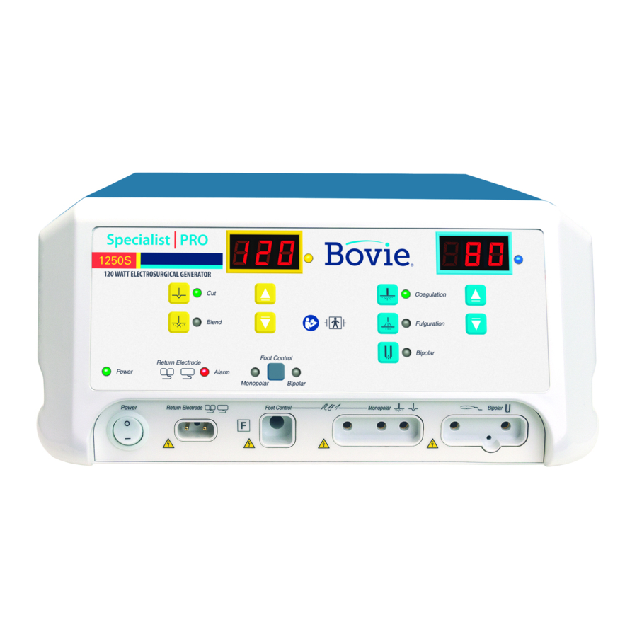
FRONT PANEL Figure 2 – 1 Layout of controls, indicators, and receptacles on the front panel Service Guide • Specialist | PRO... -
Page 20: Symbols On The Front Panel
Mandatory: Refer to instruction manual/guide. Defibrillator Proof Type BF Equipment RF Isolated – patient connections are isolated from earth at high frequency. Warning: Dangerous voltage. Power Switch and Handpiece Connectors Patient Return Electrode Monopolar Output Bipolar Output Bovie Medical Corporation... -
Page 21: Controls And Indicators Overview
CONTROLS AND INDICATORS OVERVIEW Users may control most Bovie® Specialist | PRO functions from the front panel. Each Control is plainly marked and colored on the front panel for quick reference. Volume control and a footswitch connector are located on the rear panel. -
Page 22: Cut And Blend Controls
CUT AND BLEND CONTROLS Figure 2 – 2 Controls for the Cut and Blend Modes Bovie Medical Corporation... -
Page 23: Coag And Bipolar Controls
COAG AND BIPOLAR CONTROLS Figure 2 – 3 Controls for the Coagulation, Fulguration, and Bipolar Modes Service Guide • Specialist | PRO... -
Page 24: Indicators
INDICATORS Figure 2 – 4 Indicators for power, return electrodes, and footswitch control Bovie Medical Corporation... -
Page 25: Power Switch And Receptacles
POWER SWITCH AND RECEPTACLES Figure 2 – 5 Location of the unit power switch and front panel receptacles Service Guide • Specialist | PRO... -
Page 26: Rear Panel
Please note that infected medical devices must be disposed of as medical/biohazard waste and cannot be included in used electronic equipment disposal/recycling programs. In addition, certain electronic products must be returned directly to Bovie Medical Corporation. Contact your Bovie® sales representative for return instructions. - Page 27 Service Guide • Specialist | PRO...
-
Page 28: Technical Specifications
All specifications are nominal and subject to change without notice. A specification referred to as “typical” is within ± 20% of a stated value at room temperature (25° C / 77° F) and a nominal input power voltage. Bovie Medical Corporation... -
Page 29: Performance Characteristics
PERFORMANCE CHARACTERISTICS Input Power 100 – 240 VAC Mains line frequency range (nominal): 50 – 60 Hz Power consumption: 270 VA Fuses (two): 3.15A (Slow Blow) Duty Cycle Under maximum power settings and rated load conditions (Cut, 120 watt @ 500 ohm load), the generator is suitable for activation times of 10 seconds on, 30 seconds off for one hour. -
Page 30: Audio Volume
Normal polarity, intact ground: < 10 μA Normal polarity, ground open: < 50 μA Source current, patient leads, all outputs Reverse polarity, ground open: < 50 μA < 50 μA Sink current at high line, all inputs Bovie Medical Corporation... -
Page 31: High Frequency (Rf) Leakage Current
IEC 60601-2-2 specifications regarding electromagnetic compatibility. Voltage Transients (Emergency Generator Mains Transfer) The Bovie® Specialist | PRO Electrosurgical Generator operates in a safe manner when the transfer is made between line AC and an emergency generator voltage source. Service Guide • Specialist | PRO... -
Page 32: Emc Compliance
Bovie Medical. Otherwise, degradation of the performance of Specialist | Pro could result. Understand that only the Accessories supplied with or ordered from Bovie Medical should be used with your device. The Specialist | Pro and its accessories are not suitable for interconnection with other equipment. - Page 33 The Specialist | Pro is intended for use in the electromagnetic environment listed below. The customer or the user of the Specialist | Pro should assure that it is used in such an environment. - electromagnetic immunity Immunity test Compliance Test Level ±8kV Contact IEC 61000-4-2, Electro-Static Discharge ±15kV Air...
-
Page 34: Output Characteristics
7.7 ± 20% 30 W @ 200 Ω Bipolar 520 kHz (-14 kHz, +29 kHz) 32 kHz ± 5 kHz 1200V 6.9 ± 20% * an indication of a waveform's ability to coagulate bleeders without a cutting effect. Bovie Medical Corporation... -
Page 35: Output Power Curves
OUTPUT POWER CURVES Figure 3–1 and 3–2 illustrates output voltage (Vpeak) versus power setting. Figure 3–3 illustrates output power versus power setting for all modes. Figures 3–4 through 3–8 illustrate specific output power delivered to a range of load resistances for each mode. Figure 3 –... -
Page 36: Figure 3 - 3 Output Power Versus Power Setting For All Modes
Figure 3 – 3 Output power versus power setting for all modes Figure 3 – 4 Output power versus impedance for Cut mode Bovie Medical Corporation... -
Page 37: Figure 3 - 5 Output Power Versus Impedance For Blend Mode
Figure 3 – 5 Output power versus impedance for Blend mode Figure 3 – 6 Output power versus impedance for Coagulation mode Service Guide • Specialist | PRO... -
Page 38: Figure 3 - 7 Output Power Versus Impedance For Fulguration Mode
Figure 3 – 7 Output power versus impedance for Fulguration mode Figure 3 – 8 Output power versus impedance for Bipolar mode Bovie Medical Corporation... -
Page 39: Reference Output Waveforms
Reference Output Waveforms The following figures are the output waveforms as viewed on an oscilloscope. Figure 3 – 9 Cut mode waveform Figure 3 – 10 Blend mode waveform Service Guide • Specialist | PRO... -
Page 40: Figure 3 - 11 Coagulation Mode Waveform
Figure 3 – 11 Coagulation mode waveform Figure 3 – 12 Fulguration mode waveform Bovie Medical Corporation... -
Page 41: Figure 3 - 13 Bipolar Mode Waveform
Figure 3 – 13 Bipolar mode waveform Service Guide • Specialist | PRO... -
Page 42: Theory Of Operation
THEORY OF OPERATION This section includes the following information: Block diagram Functional overview of key circuits System logic Bovie® Specialist | PRO control signal inputs and outputs. Bovie Medical Corporation... -
Page 43: Block Diagram
Figure 4 – 1 Functional block diagram of the Bovie® Specialist | PRO system FUNCTIONAL OVERVIEW OF KEY CIRCUITS The following descriptions highlight the main circuits in the Bovie® Specialist | PRO Electrosurgical Generator. Power Factor Correction Circuit (PFC) The Power Factor Correction Circuit ensures lower power consumption. The circuit is used to correct the power load that is distributed to the unit’s capacitors, providing the lowest voltage required for proper operation of the unit. -
Page 44: Speaker Circuit
When you connect a single plate patient return electrode to the unit, the Pad Sensing Module will detect if the resistance is below 25 Ω. If it is, the Bovie® Specialist | PRO will display the green single plate LED on the front of the unit. -
Page 45: Controls And Indicators
SYSTEM LOGIC The control logic uses a Field Programmable Gate Array as the “brain” of the Bovie® Specialist | PRO Electrosurgical Generator. This system interprets all of the inputs and delivers the correct corresponding outputs. Every operation of the unit is controlled from this system. -
Page 46: Bovie® Specialist | Pro Control Signal Inputs And Outputs
BOVIE® SPECIALIST | PRO CONTROL SIGNAL INPUTS AND OUTPUTS The following table lists the important input and output signals. From a troubleshooting standpoint, the absence (and presence) of these signals will help you isolate problems. Signal Name Description This is an input signal from the Temperature Sense Circuit... - Page 47 Signal Name Description This is an output signal from the system logic that controls relays on the main board. These relays direct which output jack receives the output RF power. HAND/FOOT_SEL The output power for monopolar modes is switchable from foot-controlled hand piece activation, to a handcontrolled (switching pencil) activation.
-
Page 48: Maintaining The Bovie® Specialist | Pro
MAINTAINING THE BOVIE® SPECIALIST | PRO This section includes the following information: Cleaning the unit Performing periodic inspection Replacing fuses. Bovie Medical Corporation... -
Page 49: Cleaning
Do not allow fluids to enter the chassis. Do not sterilize the generator. PERIODIC INSPECTION Every six months, visually inspect the Bovie® Specialist | PRO for signs of wear or damage. In particular, look for any of the following problems: •... -
Page 50: Troubleshooting
TROUBLESHOOTING This section includes error code descriptions and actions to take to resolve them. Bovie Medical Corporation... -
Page 51: Recommended Equipment For Troubleshooting
If an error code was displayed, take the appropriate action(s) to correct the error condition. Inspecting the Generator If the Bovie® Specialist | PRO malfunctions, check for obvious conditions that may have caused the problem. Check the generator for visible signs of physical damage. -
Page 52: Inspecting Internal Components
Lift the cover off the chassis. Save the cover and screws for later reinstallation. Visually inspect and verify that all connectors are firmly seated. Inspect each board for damaged components, wires, cracks and corrosion. Reinstall the cover by positioning the cover over the chassis, and securing the four screws. Bovie Medical Corporation... -
Page 53: Understanding Error Codes And Audio Tones
UNDERSTANDING ERROR CODES AND AUDIO TONES The Bovie® Specialist | PRO Electrosurgical Generator includes automatic, perpetual, self-diagnostics. If the diagnostics detect an error, the system displays an error code, sounds an audible tone, and deactivates the output power. Any errors detected will shut down the RF output power. -
Page 54: Correcting Common Problems
Loose or disconnected cable between Check / connect ribbon cable from the main main board and display board board to the display board. Main board malfunction Replace the main board. Display board malfunction Replace the display board. Bovie Medical Corporation... - Page 55 Situation Possible cause Recommended action Blank or confusing LED Faulty ribbon cable between Main Check / connect ribbon cable that connects display board and Display board the display board to the main board. Display board malfunction Replace the display board. Mode buttons do not operate correctly when Loose or disconnected cable between...
- Page 56 Some manufacturers offer RF choke filters for use in monitor leads. The filters reduce interference when the generator is activated and minimize the potential for an electrosurgical burn at the site of the monitor electrode. Bovie Medical Corporation...
- Page 57 Situation Possible cause Recommended action Pacemaker Intermittent connections or metal-tometal 1. Check all connections to the generator. interference Sparking 2. It may be necessary to re-program the pacemaker. Current traveling from active to return 1. Use bipolar instruments, if possible. If you must use a electrode during monopolar monopolar instrument, place the patient return electrode as Electrosurgery is passing too close to...
-
Page 58: Main Board Test Points
+75 VDC TP41, T19 (HV_GND) HIGH VOLTAGE GROUND TP20 (3.3V) + 3.3 VDC TP21 (5V) +5 VDC TP22 (12v) +12 VDC TP23 (-12V) -12 VDC TP25 (1.2V) +1.2 VDC TP35 (HVPFC_16V) +16V PFC TP37 (GND_PFC) PFC GROUND Bovie Medical Corporation... - Page 59 Service Guide • Specialist | PRO...
-
Page 60: Repair Policy And Procedures
REPAIR POLICY AND PROCEDURES Refer to this section for information on Responsibility of the manufacturer Returning the generator for service Bovie Medical Corporation... -
Page 61: Responsibility Of The Manufacturer
If necessary, contact Customer Service for the proper packaging to ship the unit. Please be sure to include a reference of the Bovie Return Materials Authorization Number on the outside of the box/container. C. Ship the generator, prepaid, to the address given to you by the Bovie Medical Corporation Service Center. Service Guide • Specialist | PRO... -
Page 62: Warranty
This warranty does not apply to any product, or part thereof, which has been repaired or altered outside Bovie Medical’s factory in a way so as, in Bovie Medical’s judgment, to affect its stability or reliability, or which has been subjected to misuse, neglect, or accident. - Page 63 This warranty is in lieu of all other warranties, express or implied, including without limitation, the warranties of merchantability and fitness for a particular purpose, and of all other obligations or liabilities on the part of Bovie Medical Corporation. Bovie Medical Corporation neither assumes nor authorizes any other person to assume for it any other liability in connection with the sale or use of any of Bovie Medical Corporation’s products.
-
Page 64: Board Drawings And Schematics
BOARD DRAWINGS AND SCHEMATICS This supplement contains the assembly drawings and schematics for the following printed circuit boards: Main board Display board Relay board Connector board Bovie Medical Corporation... -
Page 65: How To Order Parts From Bovie Medical Corporation
Our trained staff will verify the part numbers and arrange immediate delivery. The Technical Service Department can relay cost information, determine parts availability, and suggest any assembly updates available. BOVIE® SPECIALIST | PRO DESIGN BREAKDOWN & DRAWING REFERENCE PCB ASSEMBLIES... - Page 66 Bovie Medical Corporation...
-
Page 67: Bovie Drawing & Schematic Package
BOVIE DRAWING & SCHEMATIC PACKAGE Following tri-folds Service Guide • Specialist | PRO... - Page 68 Bovie Medical Corporation...
-
Page 69: Schematic 1 Main Board Top Level Block
SCHEMATIC 1 MAIN BOARD TOP LEVEL BLOCK Service Guide • Bovie® Surgi-Center│PRO... -
Page 70: Schematic 2 Main Board Rf Amplifier Circuit
SCHEMATIC 2 MAIN BOARD RF AMPLIFIER CIRCUIT Bovie Medical Corporation... -
Page 71: Schematic 3 Main Board Power Supply Block
SCHEMATIC 3 MAIN BOARD POWER SUPPLY BLOCK Service Guide • Bovie® Surgi-Center│PRO... -
Page 72: Schematic 4 Main Board Assembly Support And Mounting Holes
SCHEMATIC 4 MAIN BOARD ASSEMBLY SUPPORT AND MOUNTING HOLES Bovie Medical Corporation... -
Page 73: Schematic 5 Main Board Isolated Power Factor Corrector Circuit
SCHEMATIC 5 MAIN BOARD ISOLATED POWER FACTOR CORRECTOR CIRCUIT Service Guide • Bovie® Surgi-Center│PRO... -
Page 74: Schematic 6 Main Board Logic Power Supply Circuit
SCHEMATIC 6 MAIN BOARD LOGIC POWER SUPPLY CIRCUIT Bovie Medical Corporation... -
Page 75: Schematic 7 Main Board Audio Circuit
SCHEMATIC 7 MAIN BOARD AUDIO CIRCUIT Service Guide • Bovie® Surgi-Center│PRO... -
Page 76: Schematic 8 Display Board Top Level Block
SCHEMATIC 8 DISPLAY BOARD TOP LEVEL BLOCK Bovie Medical Corporation... -
Page 77: Schematic 9 Display Board Diagnostic Circuit
SCHEMATIC 9 DISPLAY BOARD DIAGNOSTIC CIRCUIT Service Guide • Bovie® Surgi-Center│PRO... -
Page 78: Schematic 10 Display Board Neutral Electrode Monitoring Circuit
SCHEMATIC 10 DISPLAY BOARD NEUTRAL ELECTRODE MONITORING CIRCUIT Bovie Medical Corporation... -
Page 79: Schematic 11 Display Board Control Logic Circuit
SCHEMATIC 11 DISPLAY BOARD CONTROL LOGIC CIRCUIT Service Guide • Bovie® Surgi-Center│PRO... -
Page 80: Schematic 12 Connector Panel Block
SCHEMATIC 12 CONNECTOR PANEL BLOCK Bovie Medical Corporation... -
Page 81: Schematic 13 High Voltage Relay Circuit
SCHEMATIC 13 HIGH VOLTAGE RELAY CIRCUIT Service Guide • Bovie® Surgi-Center│PRO... -
Page 82: Printed Circuit Board 1 Main Board Pcb Top View
PRINTED CIRCUIT BOARD 1 MAIN BOARD PCB TOP VIEW Bovie Medical Corporation... -
Page 83: Printed Circuit Board 2 Main Board Pcb Bottom View
PRINTED CIRCUIT BOARD 2 MAIN BOARD PCB BOTTOM VIEW Service Guide • Bovie® Surgi-Center│PRO... -
Page 84: Printed Circuit Board 3 Display Board Pcb (Top And Bottom Views)
PRINTED CIRCUIT BOARD 3 DISPLAY BOARD PCB (TOP AND BOTTOM VIEWS) Bovie Medical Corporation... -
Page 85: Printed Circuit Board 4 High Volatge Relay Pcb (Top And Bottom Views)
PRINTED CIRCUIT BOARD 4 HIGH VOLATGE RELAY PCB (TOP AND BOTTOM VIEWS) Service Guide • Bovie® Surgi-Center│PRO... -
Page 86: Printed Circuit Board 5 Connector Panel Pcb (Top And Bottom Views)
PRINTED CIRCUIT BOARD 5 CONNECTOR PANEL PCB (TOP AND BOTTOM VIEWS) Bovie Medical Corporation... -
Page 87: Assembly Drawing 1 A1250S Final Assembly
ASSEMBLY DRAWING 1 A1250S FINAL ASSEMBLY Service Guide • Bovie® Surgi-Center│PRO... -
Page 88: Assembly Drawing 2 A1250S Final Assembly
ASSEMBLY DRAWING 2 A1250S FINAL ASSEMBLY Bovie Medical Corporation... -
Page 89: Assembly Drawing 3 A1250S Final Assembly
ASSEMBLY DRAWING 3 A1250S FINAL ASSEMBLY Service Guide • Bovie® Surgi-Center│PRO... -
Page 90: Assembly Drawing 4 A1250S Back Panel Assembly
ASSEMBLY DRAWING 4 A1250S BACK PANEL ASSEMBLY Bovie Medical Corporation... -
Page 91: Assembly Drawing 5 A1250S Final Assembly
ASSEMBLY DRAWING 5 A1250S FINAL ASSEMBLY Service Guide • Bovie® Surgi-Center│PRO... -
Page 92: Assembly Drawing 6 A1250S Back Panel Assembly
ASSEMBLY DRAWING 6 A1250S BACK PANEL ASSEMBLY Bovie Medical Corporation... -
Page 93: Assembly Drawing 7 A1250S Connector Panel Board
ASSEMBLY DRAWING 7 A1250S CONNECTOR PANEL BOARD Service Guide • Bovie® Surgi-Center│PRO... -
Page 94: Assembly Drawing 8 A1250S Front Housing Assembly
ASSEMBLY DRAWING 8 A1250S FRONT HOUSING ASSEMBLY Bovie Medical Corporation... -
Page 95: Assembly Drawing 9 A1250S Rear Panel Assembly
ASSEMBLY DRAWING 9 A1250S REAR PANEL ASSEMBLY Service Guide • Bovie® Surgi-Center│PRO... - Page 96 Bovie Medical Corporation...
- Page 97 MC-55-237-002_5-EN 10/2022 Service Guide • Bovie® Surgi-Center│PRO...
Need help?
Do you have a question about the SPECIALIST PRO and is the answer not in the manual?
Questions and answers