
Related Manuals for ZALMAN GS1000


Summary of Contents for ZALMAN GS1000
- Page 1 GS1000 English version ◈ Please read this manual thoroughly before installation. ◈ Please visit the GS1000 web page at Zalman’ s website to view the GS1000 installation video. E-mail: zalman@zalman.com www.zalman.com...
-
Page 2: Table Of Contents
GS1000 ▣ Contents 1. Cautionary Notes 2. Specifications 3. Components 4. Installation Guide 5. Zalman’s Recommendations The specifications of any product may change without prior notice to improve performance... -
Page 3: Cautionary Notes
GS1000 in its original packaging for transport. ◈ ◈ Disclaimer Zalman Tech Co., Ltd. is not responsible for any damages due to external causes, including but not limited to improper use, problems with electrical power, accident, neglect, alteration, repair, improper installation, or improper testing. -
Page 4: Specifications
GS1000 2 Specifications Enclosure Type Full Tower Enclosure Dimensions 585 mm X 220 mm X 520 mm (D x W x H) (18.9 x 8.7 x 17.7 ) Weight 12kg (26.4lb) Materials Aluminum/ Plastic (ABS)/ steel (GI) Motherboard Compatibility E-ATX / Standard ATX / microATX... -
Page 5: Components
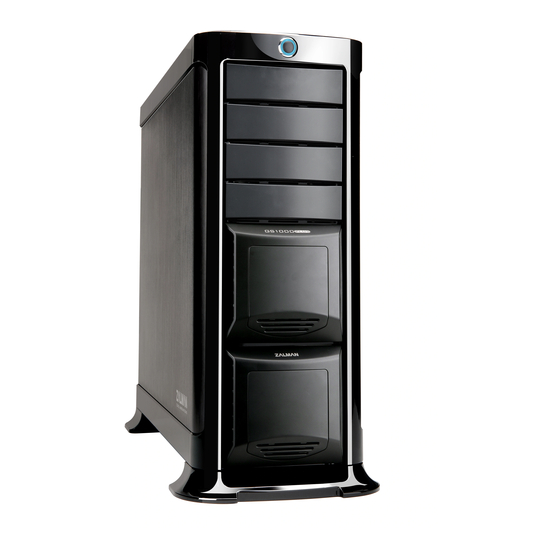
GS1000 3 Components (1) GS1000 POWER USB 2.0 Headphones IEEE 1394 Front View Back View Top View Icon Description Tools required for assembly Side View The specifications of any product may change without prior notice to improve performance... - Page 6 GS1000 (2) GS1000 Diagram and Parts Table Item Part Name Item Part Name HDD Cover Aluminum Door HDD Tray PSU Bracket 2 In 1 Bracket PSU Fan Bracket 5.25 " Bay Cover Rear Foot Chassis Front Foot Top Cover The specifications of any product may change without prior notice to improve performance...
- Page 7 GS1000 (3) Included GS1000 Parts Diagram Part Specification Qty Description ABS+Spray Foot (matches case Enclosure Support (FRONT/REAR) color) For Power M/B Power Extension 12V Extension Cable Cables Cable (8PIN) PH #6-32*6 Use with microATX M/B Stand Off (Silver) M/Bs #6-32*12...
-
Page 8: Installation Guide
GS1000 4 Installation Guide (1) Installation of the Front & Rear Feet PWH M3*12 Front Foot Rear Foot (2) Removal of the Side Panels The specifications of any product may change without prior notice to improve performance... - Page 9 GS1000 (3) Installation of the Power Supply 1) PSU Bracket Removal TYPE TYPE #6-32*6 2) PSU Bracket Installation TYPE TYPE The specifications of any product may change without prior notice to improve performance...
- Page 10 GS1000 (4) Installation of the M/B and Add-On Card(s) 1) M/B Installation #6-32*6 micro ATX motherboards Server motherboards 2) Graphic Card Installation The specifications of any product may change without prior notice to improve performance...
- Page 11 GS1000 (5) 5.25 and 3.5 Drives 1) 5.25 Drive Panel Removal 2) 5.25 ODD Drive Installation The specifications of any product may change without prior notice to improve performance...
- Page 12 GS1000 3) 5.25 Bay FDD / HDD installation 1 FDD Installation M3 * 5 2 HDD Installation The specifications of any product may change without prior notice to improve performance...
- Page 13 GS1000 (6) HDD Installation 1) 3.5 HDD Tray Removal 1. Press both corners towards the center. 2. Pull the handle with another finger or hand. The specifications of any product may change without prior notice to improve performance...
- Page 14 GS1000 2) 3.5 HDD Installation Push the hooks as shown in the Diagram of released hooks. diagram 3.5 " HDD 3.5 " HDD 3.5 " HDD 3) HDD Installation #6-32*12 Note) To transport a fullly assembled system, use a bolt to fixate the HDD lock as shown in figure.
- Page 15 Note) For safe installation and removal of HDD’s, please turn the computer OFF before proceeding. SATA cables not provided with the GS1000. Please purchases or use that of another source. The specifications of any product may change without prior notice to improve performance...
- Page 16 GS1000 (8) Power Button / LED and Front I/O Cables 1) Power Cable If the Power LED Connector is installed in reverse the power LED will not operate properly. Please refer to the motherboard’s manual before connecting the Power LED.
- Page 17 GS1000 2) Front I/O Cables Note) Precautions for Cable Connections Please refer to the motherboard’s manual when connecting the USB 2.0, IEEE1394a and audio connectors. Do not connect the USB2.0 connector to the IEEE1394a connector, or vice versa. This may cause serious damage to the product.
-
Page 18: Zalman's Recommendations
GS1000 5 Zalman’ s Recommendations (1) Use of an optional 120mm fan on the top panel of the case will improve cooling performance. (2) Use of an optional 120mm fan on the bottom panel of the case will improve cooling peformance as well. - Page 19 GS1000 2) Installing a 2nd Fan (3) Adding a 2nd Hot Swap PCB (optional) (4) Zalman Recommended Products for GS1000 CNPS9700 GV1000 ZM-F3 LED ZM850-HP ZM-NBF47 CPU Cooler VGA Cooler LED Fans Northbridge Cooler The specifications of any product may change without prior notice to improve performance...
Need help?
Do you have a question about the GS1000 and is the answer not in the manual?
Questions and answers