
Related Manuals for ZALMAN LQ1000


Summary of Contents for ZALMAN LQ1000
- Page 2 Disclaimer Visit our website and watch the Z-Machine LQ1000 installation Zalman Tech Co., Ltd. is not responsible for any damages due to external causes, including video for an installation overview. but not limited to, improper use, problems with electrical power, accident, neglect, alteration, repair, improper installation, or improper testing.
- Page 3 Table of Contents 2. Parts List 1. Specifications 2.1 Front View 2. Parts List 3. Components 4. Installation Guide 5. Leakage Inspection and Test Run 1. Specifications Enclosure Dimensions (L x W x H) 480mm X 220mm X 450mm Weight 15kg (33lb) Material Aluminum Alloy...
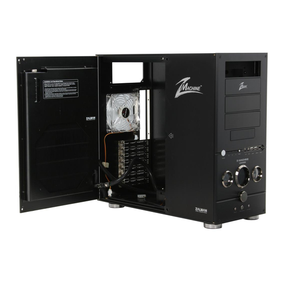
- Page 4 3. Components 2.2 Side View Water Tank (Reservoir) (1) Enclosure (5) Funnel Tool-Free Bolt Reservoir Cap 120mm Fan (6) Silicone Tube (1m) (2) CPU Water Block (ZM-WB5) (7) 220mm LED Fan Reservoir Window (3) Jump Cable (8) 220mm LED Fan Grill (4) Anti-Corrosion Coolant (ZM-G300) (9) User’s Manual Radiator...
- Page 5 4.4 Motherboard Installation 4. Installation Guide A bolt, #6-32*10(Black) Secure the motherboard to the enclosure, then, install components (CPU, VGA, RAM, etc.) 4.1 Power Supply Installation onto the motherboard. Unscrew the four Bolts (Bolt, FH M3x6) as shown in the diagram to open the Doors. Clip Support for Socket 775 Place the PSU on the Power Bracket, and screw the four Bolts (A bolt, #6-32*10 (Black)) from outside the enclosure.
- Page 6 4.6 Hard Disk Drive Installation 4.7 Cable Connection Button PCB Improper connection of the Power LED and HDD LED can lead to LED malfunction. Please refer to your motherboard’s manual before making cable connections. HDD chassis 4.8 Front I/O Connection Lock Bar Certain motherboards have different configurations for the IEEE1394a, USB2.0, and audio connectors from the one shown in the diagram below.
- Page 7 4.10 Installation Troubleshooting 4.9 Silicone Tube Connection (1) Please refer to the manual included with the CPU waterblock (ZM-WB5) for installation Refer to the diagram below as a reference for the coolant’s circulation path/ order. guides. (2) The user can add optional VGA and Northbridge waterblocks. (3) Use Needle - Nose Pliers to loosen and pull back the Tube Clamp on the tip of the Tube connecting the Water Pump’s outlet to the Tube Nipple, then disconnect the Tube from Tube Nipple.
- Page 8 (10) Connect the PSU’s Main Connector and the CPU 4-Pin Connector to the motherboard. drop when the coolant begins circulating. please pour additional coolant up to the “High Leve” (11) To prevent coolant leakage the LQ1000 Must be set upright on its feet before proceeding mark.
- Page 9 5.3 220mm Fan Installation 5.4 Front Panel Display (1) Install the provided 220mm Fan and Ffan Grill as shown in the diagram below. (2) Connect the 220mm Fan’s 3-Pin Connector to the Black 3-Pin Connector. (3) After the Fan is installed, please be cautious to prevent inference between or among Tubes and/or cables.
- Page 10 Zalman Computer Noise Prevention System Stable performance and a noiseless liquid cooling system can both be achieved with the use of Zalman’s Ultra Quiet Power Supply, VGA Water Block, Northbridge Water Block and Super Thermal Grease. Ultra Quiet Power Supply...
Need help?
Do you have a question about the LQ1000 and is the answer not in the manual?
Questions and answers