ZiLOG Z80 User Manual
Pio module for rc2014
Hide thumbs
Also See for Z80:
- User manual (306 pages) ,
- Handbook (297 pages) ,
- Reference card (16 pages)

Related Manuals for ZiLOG Z80


Summary of Contents for ZiLOG Z80
- Page 1 Module Module RC2014 RC2014 User Guide User Guide module: SC103 version module: SC103 version Design and Documentation by Stephen C Cousins Edition 1.0.0...
-
Page 2: Table Of Contents
CONTENTS ........................ 2 VERVIEW ..................... 3 RINTED IRCUIT OARD ....................... 4 CHEMATIC .......................5 & W ..........7 OMPONENTS HERE ..................... 15 SSEMBLY UIDE PIO M ................. 26 ONFIGURING THE ODULE ....................27 DDRESS ELECTION ..............29 URCHASING THE RINTED IRCUIT OARD ...................... -
Page 3: Overview
Overview The Z80 PIO module (SC103) provides two 8-bit parallel ports with handshaking and flexible input and output connectivity, as well as support for Z80 mode 2 interrupt daisy chaining. Each port has eight bidirectional data lines and two handshaking lines. The PIO has flexible interrupt generation and fully supports Z80 mode 2 interrupts. -
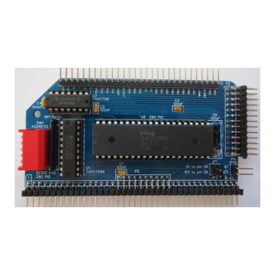
Page 4: Printed Circuit Board
Printed Circuit Board The printed circuit board is a standard footprint RC2014 board. Printed circuit board, top/component side: Printed circuit board, bottom/solder side:... -
Page 5: Schematic
Schematic Errata Version 1.0 of the PCB has the RC2014 IEI (pin 38) and IEO (pin 39) incorrectly labelled. The labels are incorrectly shown next to pins 37 and 38, not 38 and 39. Also port A I/O lines are not correctly labelled on the back of the board. The labels on the front of the board are correct though. -
Page 6: What You Need
JP2, and P1 to P4 may need to be cut from longer strips. Image Reference Description Printed circuit board SC103 Z80 PIO C1, 2, 3, 4 Capacitor 100nF, ceramic, lead spacing = 2.54mm Capacitor 100uF, electrolytic, lead spacing = 2.54mm (radial) or 14mm (axial) - Page 7 Z80 PIO, 8MHz, Z84C2008PEG (or Z80 PIO, 10MHz, Z84C2010PEG), PDIP 40 U2 socket 40 pin PDIP IC socket 0.6" wide 74HCT08, quad 2-input AND gate U3 socket 14 pin PDIP IC socket 0.3" wide Also required to assemble the module from the above components: ...
-
Page 8: Components: What They Do & Where To Get Them
Further savings are usually possible by ordering parts direct from countries like China. Image Reference Description Printed circuit board SC103 Z80 PIO Supplier Part number EasyEDA Search EasyEDA.com for RC2014 PIO The PCB is currently only available to be ordered from EasyEDA.com, although you... - Page 9 Image Reference Description Capacitor 100uF, electrolytic, lead spacing = 2.54mm (radial) or 14mm (axial) Supplier Part number Farnell 9452478 (100uF, 16V, radial) Mouser 140-REA101M1CBK0611P (100uF, 16V, radial) 711-0933 (100uF, 16V, radial) This capacitor provides suppression of transients on the power supply. The PIO module may well be used to power and control external electronics, in which case there could be significant transients generated on the supply lines.
- Page 10 JP1 and J2 Image Reference Description JP1 and JP2 Jumper shunt for pin spacing = 2.54mm Supplier Part number eBay 201261690156 Farnell 2396303 Mouser 649-68786-102LF 674-2397 These shunts (small sockets) connect the required pins on JP1 and J2. Image Reference Description Pin header, male, angled, 2-row x 39-pin, 2 row (1 row optional)
- Page 11 Image Reference Description Pin header, male, 2 rows x 13 pins, angled Supplier Part number eBay 200906546562 (2x40 pin to be cut to length) Farnell 1097962 (2x40 pin to be cut to length) Mouser 571-9-103795-0 (2x40 pin to be cut to length) 155-743 (2x40 pin to be cut to length) This connector provides access to all the PIO I/O signals in a format suitable to connect to external devices via a ribbon cable.
- Page 12 710-61304011021 (1x40 pin to be cut to length) 156-077 (1x40 pin to be cut to length) As the official RC2014 backplanes do not provide a Z80 mode 2 interrupt daisy chain (IEI and IEO signals), these have been brought to the back of the board where they can be easily linked to other modules with Dupont wires.
- Page 13 Image Reference Description DIP switch, 6 way, piano style Supplier Part number eBay 262361463572 Farnell 2452331 Mouser 653-A6FR-6104 (black) 877-2359 This switch is used to set the I/O address for the module. It sets the required state of address lines A2 to A7, thus allowing the module to occupy a 4 address block on any 4-byte boundary.
- Page 14 692-Z84C4010PEG (10 MHz version) 625-9040 (8 MHz version) The Z80 PIO provides provides two 8-bit parallel ports with handshaking and flexible interrupt functions. It has mode 2 interrupt support, making it a usual general purpose I/O chip for use in an expanded Z80 system.
- Page 15 Image Reference Description 74HCT08, quad 2-input AND gate Supplier Part number Farnell 9591796 Mouser 595-CD74HCT688E 527-514 This integrated circuit provides a special reset signal to the PIO. There is no separate reset pin on the PIO, so instead the M1 pin has an extra function. When M1 is low and both RD and IORQ are high, the PIO enters a reset state.
-
Page 16: Assembly Guide
Assembly Guide This guide assumes you are familiar with assembling circuit boards, soldering and cleaning. If not, it is recommended you read some of the guides on the internet before continuing. First check you have all the required components, as listed in the section “What You Need”. - Page 17 Step 2 Fit and solder capacitors C1, C2, C3 and C4. These can be fitted either way round, as they are not polarity dependent.
- Page 18 Step 3 Fit and solder resistor pack RP1. This must be fitted the correct way round. The component should have pin 1 marked with a dot, as illustrated right.
- Page 19 Step 4 Fit and solder connector P1. You can fit just a single row header as used by the RC2014 standard bus. The only reasons for the second row is to provide additional power supply pins, make the module the same height as the others and to increase stability of the module. To prepare the header, it should first be cut to length (if starting with a strip more than 39 pins long) and then unwanted pins must...
- Page 20 Step 5 Fit and solder connector P2. Take care to ensure the pins are parallel to the circuit board.
- Page 21 Step 6 Fit and solder connector P3 and P4. Take care to ensure the pins are parallel to the circuit board. Connector P3 is optional, so if you want to put the RC2014 in a case or just don’t like the look of it, you can leave this connector off.
- Page 22 Step 7 Fit and solder header pins JP1 and JP2. JP1 and JP2 are made up of a single header 2 pins by 2 pins as illustrated right.
- Page 23 Step 8 Fit and solder the DIP switch SW1. In order to provide some certainty for software it is strongly recommended you set the base address of your first PIO module to 0x68. The module then occupies I/O addresses 0x68 to 0x6B. This is done by setting the switches as illustrated below. If you have a second PIO module the recommended base address is 0x6C.
- Page 24 Step 8 Fit and solder capacitor C5. The PCB allows for a radial or axial capacitor. In order to build a low profile board, the capacitor should lay on its side. An axial capacitor would be most secure in this configuration, but there is limited length allocated and you probably don’t have one! You can fit a radial capacitor on its side, but it is not as secure as an axial package as both leads come out of the same end.
- Page 25 Step 10 Remove any solder ‘splats’ with a brush, such as an old toothbrush. Visually inspect the soldering for dry joints and shorts. Clean the flux off with suitable cleaning materials. Visually inspect again. Before fitting the ICs or jumper shunts, plug the board into an RC2014 backplane with no other boards fitted.
- Page 26 Step 11 Insert the ICs into their sockets, taking care to insert them the right way round, as illustrated below. Be careful not to bend any legs over. Now plug the PIO module into the RC2014 backplane together with your normal working set of modules.
-
Page 27: Configuring The Pio Module
2, it will be necessary to set up an interrupt daisy chain. This is fully described in the Z80 peripherals data sheet, but essentially it requires linking the output (IEO) of one interrupt generating device to the input (IEI) of the next, and so on. -
Page 28: Address Selection
Address Selection The module’s address can be set to any address that is a multiple of 4, such as address 0, 4, 8, 12, 16, … , 252. This address is known as the base address, with the module occupying this address plus the next three addresses. Thus if the base address is 0, then the module occupies the address range 0 to 3. - Page 29 The following table shows examples of address switch settings. Switches Base Address Address Range Recommended 0x68 hexadecimal 0x68 to 0x6B hexadecimal PIO module (104 decimal) (104 to 107 decimal) address 0x6C hexadecimal 0x6C to 0x6F hexadecimal PIO module (108 decimal) (108 to 111 decimal) address 0x00 hexadecimal...
-
Page 30: Purchasing The Printed Circuit Board
Select the main menu item “Explore” In the search box, enter “RC2014 PIO” or “sccousins” Select, from the list shown, the project “SC103 v1.x Z80 PIO for RC2014” The project’s details should now be displayed. From here you can select “Download Gerber” or “Order at JLCPCB”. You also have the option to “Open in Editor”... - Page 31 Select “Checkout securely” Enter your details and select your shipping options. And finally complete the order. Warning You may get a warning about design rule violations. There are 2 legitimate warnings that may be reported due to the position of the last pair of holes on the RC2014 bus connector being too close to the edge of the board when using the standard RC2014 board outline.
-
Page 32: Fault Finding
Fault Finding Check all links and jumpers, check no chips have bent legs and thus not making contact with their socket, carefully inspect all soldering, check all the chips are inserted the right way round, check all the components are in the right place. With the PIO module plugged in to the RC2014 backplane with no other boards fitted. -
Page 33: History
History 2018-06-25 v1.0 First circuit boards... -
Page 34: Contact Information
Stephen C Cousins, Chelmsford, Essex, United Kingdom. RC2014 information Information about the RC2014 system can be found at www.rc2014.co.uk RC2014 support Issues related to the RC2014 can be posted on the google group “RC2014-Z80”. RC2014 supplies Parts can be purchased through Tindie at www.tindie.com (search “RC2014”) Official RC2014 parts are at: https://www.tindie.com/stores/Semachthemonkey/?ref=offsite_badges&utm_sour...
Need help?
Do you have a question about the Z80 and is the answer not in the manual?
Questions and answers