Moxa Technologies EtherDevice EDR-G902 Hardware Installation Manual
Hide thumbs
Also See for EtherDevice EDR-G902:
- Hardware installation manual (14 pages) ,
- User manual (79 pages) ,
- Quick installation manual (13 pages)
Table of Contents
Advertisement
Quick Links
Download this manual
See also:
User Manual
Advertisement
Table of Contents

Related Manuals for Moxa Technologies EtherDevice EDR-G902


Summary of Contents for Moxa Technologies EtherDevice EDR-G902
- Page 1 EDR-G902/G903 Hardware Installation Guide Moxa EtherDevice™ Router Third Edition, May 2014 2014 Moxa Inc. All rights reserved. P/N: 1802009030012...
-
Page 2: Package Checklist
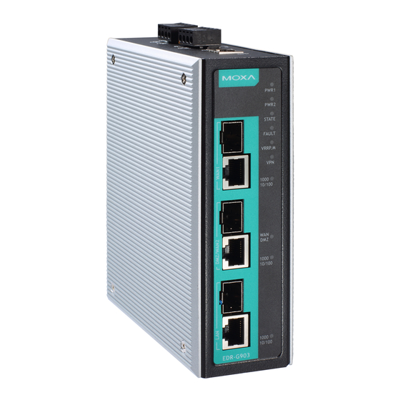
Package Checklist The Moxa EtherDevice Router is shipped with the following items. If any of these items is missing or damaged, please contact your customer service representative for assistance. • 1 EtherDevice Router • Hardware Installation Guide • CD-ROM with User’s Manual and Windows utility •... - Page 3 Panel Views of EtherDevice Router EDR-G903 Front Panel: 1. WAN1, DMZ/WAN2, LAN port: 10/100/1000 BaseT(X) or 100/1000Base SFP slot combo ports 2. Power input PWR1 LED 3. Power input PWR2 LED 4. Fault LED 5. 10/100/1000BaseT(X) LED indicator 6. LED for DMZ/WAN2 port EDR-G902 Front Panel: 1.
-
Page 4: Mounting Dimensions
Top Panel: 1. Grounding screw 2. 4-pin terminal block for PWR 1, PWR 2 3. 4-pin terminal block for DI and Relay 4. RS-232 console port Rear Panel: 1. Terminal block 2. DIN-Rail kit Mounting Dimensions Unit = mm (inch) - 4 -... -
Page 5: Din-Rail Mounting
DIN-Rail Mounting The aluminum DIN-Rail attachment plate should already be fixed to the back panel of the EtherDevice Router when you take it out of the box. If you need to reattach the DIN-Rail attachment plate to the EtherDevice Router, make sure the stiff metal spring is situated towards the top, as shown in the following figures. - Page 6 ATTENTION Safety First! Be sure to disconnect the power cord before installing and/or wiring your Moxa EtherDevice Router. Calculate the maximum possible current in each power wire and common wire. Observe all electrical codes dictating the maximum current allowable for each wire size. If the current goes above the maximum ratings, the wiring could overheat, causing serious damage to your equipment.
-
Page 7: Wiring The Relay Contact
Wiring the Relay Contact The EtherDevice Router has one set of relay outputs. This relay contact uses one contacts of the terminal block on the EtherDevice Router’s top panel. Refer to the next section for detailed instructions on how to connect the wires to the terminal block connector, and how to attach the terminal block connector to the terminal block receptor. -
Page 8: Wiring The Digital Inputs
Wiring the Digital Inputs The EtherDevice Router has one set of digital input, DI. The DI consists of two left contacts of the 4-pin terminal block connector on the EtherDevice Router’s top panel, which are used for the DC inputs. The top and front views of one of the terminal block connectors are shown here. - Page 9 RJ45 (10-pin) to DB9 (F) Cable Wiring 10/100/1000BaseT(X) Ethernet Port Connection The 10/100/1000BaseT(X) ports located on Moxa EtherDevice Router’s front panel are used to connect to Ethernet-enabled devices. Most users will choose to configure these ports for Auto MDI/MDI-X mode, in which case the port’s pinouts are adjusted automatically depending on the type of Ethernet cable used (straight-through or cross-over), and the type of device (NIC-type or HUB/Switch-type) connected to the port.
- Page 10 RJ45 (8-pin) to RJ45 (8-pin) Straight-Through Cable Wiring RJ45 (8-pin) to RJ45 (8-pin) Cross-Over Cable Wiring 100 BaseFX or 1000BaseSFP Fiber Port The Gigabit Ethernet ports on the EtherDevice Router are SFP slots, which require 100BaseFX SFP or Gigabit mini-GBIC fiber transceivers to work properly.
-
Page 11: Led Indicators
ATTENTION This is a Class 1 Laser/LED product. To avoid causing serious damage to your eyes, do not stare directly into the Laser Beam. LED Indicators The front panel of the Moxa EtherDevice Router contains several LED indicators. The function of each LED is described in the following table: Color State Description... -
Page 12: Specifications
Specifications Technology Standards IEEE 802.3 for 10BaseT IEEE 802.3u for 100BaseT(X) and 100BaseFX IEEE 802.3ab for 1000BaseT(X) IEEE 802.3z for 1000BaseX Protocols SNMPv1/v2c/v3, DHCP Server/Client, TFTP, NTP, HTTP, HTTPS, Telnet, SSH, Syslog, SMTP, LLDP, PPPoE, PPTP, Dynamic DNS, QoS (Quality of Service) Flow Control IEEE 802.3x flow control, back pressure flow... - Page 13 Technical Support Contact Information www.moxa.com/support Moxa Americas: Moxa China (Shanghai office): Toll-free: 1-888-669-2872 Toll-free: 800-820-5036 Tel: 1-714-528-6777 Tel: +86-21-5258-9955 Fax: 1-714-528-6778 Fax: +86-21-5258-5505 Moxa Europe: Moxa Asia-Pacific: Tel: +49-89-3 70 03 99-0 Tel: +886-2-8919-1230 Fax: +49-89-3 70 03 99-99 Fax: +886-2-8919-1231 - 13 -...