Table of Contents
Advertisement
Quick Links
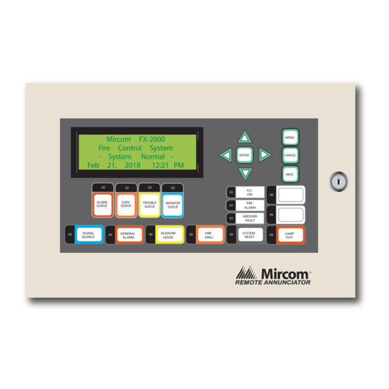
RAX-LCD
Remote FX-2000 Annunciator Panel
Feb 21, 2018
SIGNAL
SILENCE
Installation and Wiring Manual
Mircom FX-2000
Fire Control System
- System
Normal -
12:21 PM
ALARM
SUPV.
TROUBLE
MONITOR
QUEUE
QUEUE
QUEUE
QUEUE
ACKNOW-
GENERAL
ALARM
LEDGE
MENU
ENTER
CANCEL
INFO
A.C.
ON
PRE-
ALARM
GROUND
FAULT
FIRE
SYSTEM
LAMP
DRILL
RESET
TEST
REMOTE ANNUNCIATOR
LT-856 Rev 9
February 2018
Advertisement
Table of Contents

Related Manuals for Mircom RAX-LCD


Summary of Contents for Mircom RAX-LCD
- Page 1 RAX-LCD Remote FX-2000 Annunciator Panel Mircom FX-2000 MENU Fire Control System - System Normal - ENTER CANCEL Feb 21, 2018 12:21 PM INFO A.C. ALARM SUPV. TROUBLE MONITOR PRE- QUEUE QUEUE QUEUE QUEUE ALARM GROUND FAULT SIGNAL ACKNOW- FIRE SYSTEM...
-
Page 3: Table Of Contents
The RAX-LCD Shared Display Chassis ................. Specifications and Features Enclosure Models ......................Module Models ....................... 5.2.1 RAX-LCD Remote FX-2000 Shared Display LCD Annunciator ........5.2.2 RAX-1048TZDS Adder Annunciator Chassis (48 Display Points) ........Current Drain for Battery Calculations ................Environmental Specifications .................. - Page 4 List of Figures and Tables Table 1 Backboxes ........................Figure 1 Mechanical Assembly Diagram ..................Figure 2 Wiring Diagram ....................... Figure 3 Annunciator Panel Connections ..................Table 2 Maximum Wiring Run to Last Annunciator ..............Table 3 Annunciator “Address” Settings ..................Figure 4 Annunciator Connections ....................
-
Page 5: Introduction
Introduction Mircom's FX-2000's remote shared display is the RAX-LCD. The RAX-LCD shared display provides an exact replica (less 16 zone LEDs) of the main FX-2000 Fire Alarm Panel display at a remote location. It is equipped with a large 4 line x 20 character back-lit alphanumeric LCD display that uses a simple menu system complete with a directional keypad and switches for Enter, Menu Cancel and Info. -
Page 6: Installation Instructions
Installation Instructions Table 1 Backboxes Backbox Height H (in.) Width (in.) Mounting A (in.) Mounting B (in.) BB-1001D/R 9.0” 12.75” 9.95” 7.5” BB-1002D/R 18.0” 12.75” 9.95” 16.5” BB-1003D/R 26.5” 12.75” 9.95” 24.9” BB-1008D/R 33.0” 22.5” 20.9” 35.2” BB-1012D/R 45.0” 22.5” 20.9”... -
Page 7: Wiring Instructions
No star wiring or T-tapping is 24 VDC POWER FROM FIRE ALARM CONTROL allowed. Each RAX-LCD 24 VDC PANEL OR PREVIOUS ANNUNCIATOR INPUT Shared Display has a 120... -
Page 8: Dip Switch Settings
SW1-6 and SW1-1 OFF and all the other DIP SW1-8 during power up. At switches are ON. all other times put in “ON” state. The OFF setting is active. The addresses available for the RAX-LCD are 33 to 63. Set the address as follows in the table below:... - Page 9 Table 3 Annunciator “Address” Settings Address SW1-1 SW1-2 SW1-3 SW1-4 SW1-5 Address SW1-1 SW1-2 SW1-3 SW1-4 SW1-5...
-
Page 10: The Rax-1048Tzds Adder Annunciator Chassis
SILENCE LEDGE DRILL RESET or IPS-2424DS. ALARM TEST RAX-LCD SHARED DISPLAY BOARD The RAX-LCD Shared Figure 4 Annunciator Connections Display Chassis P1: Connects to the first RAX-1048TZDS or IPS-2424DS. P2: BDM port. Terminals: See Wiring Instructions on page 3 for details. -
Page 11: Specifications And Features
Standby: 100 mA Max., All LEDs ON: 150 mA Max. 5.2.2 RAX-1048TZDS Adder Annunciator Chassis (48 Display Points) • Interconnect via one ribbon cable from RAX-LCD or to previous RAX-1048TZDS or IPS- 2424DS to the next RAX-1048TZDS or IPS-2424DS. •... -
Page 12: Current Drain For Battery Calculations
Current Drain for Battery Calculations The following are the currents for the RAX-LCD to which is added the number of RAX- 1048TZDS and/or IPS-2424DS used: Normal Standby Current = 100 mA+ [________ X 15 mA] + [________ X 10mA] =_______... -
Page 13: Warranty And Warning Information
As the only individual in contact with system users, please bring each item in this warning to the attention of the users of this Mircom System. Failure to properly inform system end-users of the circumstances in which the system might fail may result in over-reliance upon the system. - Page 14 11. Battery Failure. If the Mircom System or any device connected to the system operates from batteries it is possible for the batteries to fail. Even if the batteries have not failed, they must be fully charged, in good condition, and installed correctly.
- Page 15 20. Integrated Products. Mircom System might not function as intended if it is connected to a non-Mircom product or to a Mircom product that is deemed non-compatible with a particular Mircom System.
- Page 16 U.S.A © Mircom 2018 25 Interchange Way 4575 Witmer Industrial Estates Printed in Canada Vaughan, ON L4K 5W3 Niagara Falls, NY 14305 Subject to change without prior notice Tel: (888) 660-4655 Tel: (888) 660-4655 (905) 660-4655 (905) 660-4655 www.mircom.com Fax: (905) 660-4113...
Need help?
Do you have a question about the RAX-LCD and is the answer not in the manual?
Questions and answers