
Related Manuals for Fronius Robacta Reamer V Twin


Summary of Contents for Fronius Robacta Reamer V Twin
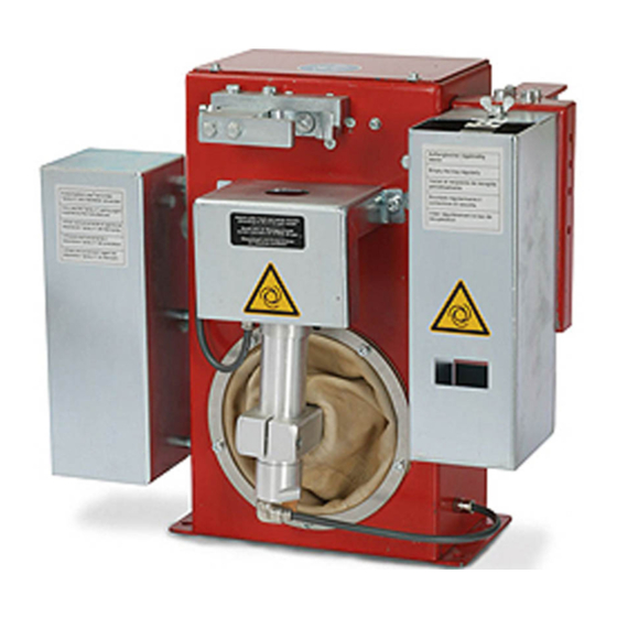
- Page 1 Operating Instructions Robacta Reamer V Twin Operating instructions 42,0426,0142,EN 024-29082022...
-
Page 3: Table Of Contents
Transport notices on the packaging Controls, connections and mechanical components Safety Safety Robacta Reamer V Twin control elements, connections and mechanical components Control elements, connections and mechanical components Standard I/O connecting plug (X1) pin assignment for robot control General Standard I/O (X1) connecting plug pin assignment... - Page 4 Cleaning position of the welding torch with externally routed coolant lines Cleaning position of the welding torch with internally routed coolant lines Fitting the clamping system for welding torches with internally routed coolant lines Tools required Removing the existing clamping system Fitting the Twin clamping system Adjusting the lifting device Adjusting the lifting device...
- Page 5 Troubleshooting Safety Safety Troubleshooting Errors in program sequence Technical data Technical data Robacta Reamer V Twin Appendix Circuit diagram Robacta Reamer V Twin Robacta Reamer V Twin pneumatic diagram Declaration of conformity...
-
Page 6: Safety Rules
Safety rules Explanation of DANGER! safety notices Indicates immediate danger. ▶ If not avoided, death or serious injury will result. WARNING! Indicates a potentially hazardous situation. ▶ If not avoided, death or serious injury may result. CAUTION! Indicates a situation where damage or injury could occur. ▶... -
Page 7: Proper Use
Proper use The device is to be used exclusively for its intended purpose. The device is intended solely for the mechanical cleaning of Fronius robot weld- ing torches in automatic mode. Any use above and beyond this purpose is deemed improper. The manufacturer shall not be held liable for any damage arising from such usage. -
Page 8: Protecting Yourself And Others
The device must be incorporated into a higher-level safety system within a se- cured area. If this area has to be accessed when setup and maintenance work is carried out, make sure that the entire system is switched off for the duration of the work in this area and that it is prevented from starting up accidentally, e.g. -
Page 9: Emc Measures
EMC device classification as per the rating plate or technical data. EMC measures In certain cases, even though a device complies with the standard limit values for emissions, it may affect the application area for which it was designed (e.g. when there is sensitive equipment at the same location, or if the site where the device is installed is close to either radio or television receivers). -
Page 10: Safety Measures In Normal Operation
Safety measures Only operate the device if all safety devices are fully functional. If the safety in normal opera- devices are not fully functional, there is a risk of tion injury or death to the operator or a third party, damage to the device and other material assets belonging to the operator, inefficient operation of the device. -
Page 11: Disposal
Disposal Waste electrical and electronic equipment must be collected separately and re- cycled in an environmentally-friendly way, in accordance with the European Dir- ective and national legislation. Used equipment must be returned to the distrib- utor or disposed of via an approved local collection and disposal facility. Correct disposal of used equipment promotes the sustainable recycling of material re- sources. -
Page 13: General
General... -
Page 15: General
Device concept The clamping device on the front of the Robacta Reamer V Twin holds the gas nozzle in place during cleaning. A cleaning cutter is used to clean the nozzle. After the cleaning process, a parting agent is applied to the inside and front of the gas nozzle through the spray nozzle that is fixed in the middle of the cleaning motor. -
Page 16: Scope Of Supply
The "Robacta Reamer" parting agent (item number 42,0411,8042) and the cleaning cutter are not part of the scope of supply. Robacta Reamer V Twin clean- ing device with wire cutter Spatter tray Tightening key for cleaning mo- Compressed air relief valve... -
Page 17: Warning Notices On The Device
Warning notices The Robacta Reamer V Twin is fitted with warning notices and a rating plate. The on the device warning notices and rating plate must not be removed or painted over. Type Art.No. Chargen No. Wels - Austria 24 V p max 6 bar (87psi.) - Page 18 Wear eye protection Notice warning of automatic start-up of the device...
-
Page 19: Transport
Transport Transport The device is to be transported by the following devices: devices On pallets using a forklift truck On pallets using a lift truck Manual WARNING! Danger from machines and objects falling. This can result in serious injury and damage to property. ▶... -
Page 21: Controls, Connections And Mechanical Components
Controls, connections and mechan- ical components... -
Page 23: Safety
Safety Safety Observe the following safety rules when using all functions described in the "Controls, connections and mechanical components" section. WARNING! Danger from incorrect operation! This can result in serious injury and damage to property. ▶ The functions described must only be used by trained and qualified person- nel. -
Page 24: Robacta Reamer V Twin Control Elements, Connections And Mechanical Components
Robacta Reamer V Twin control elements, con- nections and mechanical components Control ele- ments, connec- tions and mech- anical compon- (13) ents (12) (11) (10) Side view Front view Standard I/O connection socket (X1) For a + 24 V DC supply CAUTION! Danger from overcurrent. - Page 25 Cleaning motor with parting-agent injection nozzle The cleaning motor drives the cleaning cutter (10) Protective cover (11) Cleaning cutter With internal through hole for the parting-agent injection nozzle (12) Gas nozzle clamping device Holds the gas nozzle in place during cleaning (13) Wire cutter (15)
-
Page 26: Standard I/O Connecting Plug (X1) Pin Assignment For Robot Control
The cable harness must be adapted to the connection technology on the robot control. Standard I/O Input and output signals on the (X1) connecting Robacta Reamer V Twin: plug pin assign- Clamp gas nozzle/Cleaning motor ment ON (cleaning cutter turning) input... -
Page 27: Installation And Commissioning
Installation and commissioning... -
Page 29: Safety
Safety Safety Observe the following safety rules for all work described in the "Installation and commissioning" section. WARNING! Danger due to incorrect operation and incorrectly performed work. This can result in serious injury and damage to property. ▶ All activities described in these Operating Instructions may only be carried out by trained and qualified personnel. -
Page 30: Ensuring That The Cleaning Device Is Depressurised
WARNING! Danger from power supply and/or compressed air supply to the cleaning device! The following conditions can lead to serious injuries: rotating cleaning cutters lifting device moving up/down extending/retracting gas nozzle clamping device activated wire cutter flying parts (shavings, etc.) compressed air/parting agent mixture escaping from the parting-agent injection nozzle If work has to be performed on the cleaning device while it is being supplied with... -
Page 31: Before Commissioning
Before commissioning Proper use The cleaning device is to be used exclusively for cleaning Fronius robot welding torches, especially the gas nozzle and its interior, in automatic mode and within the scope of the technical data. Any use above and beyond this purpose is deemed improper. -
Page 32: Measures For The Safe Operation Of The Device With Untrained Personnel
Measures for the If untrained operators have access to the device, its compressed air supply must safe operation of be disconnected for the duration of work in accordance with 'Performance Level the device with d' of the ISO 13849-1 standard. untrained per- sonnel To ensure that the compressed air supply is interrupted as required, MS6-SV... -
Page 33: Screwing The Cleaning Device To The Underlying Surface
Screwing the cleaning device to the underlying surface Screwing the NOTE! cleaning device and installation Different fixings may be required to set up the installation stand depending on stand to the un- the type of underlying surface (foundation). derlying surface Fixings are therefore not included in the scope of supply of the installation stand. - Page 34 Position the spatter tray on the cleaning device as shown For an underlying surface (foundation) thickness of less than 5 mm (0.197 in.): Securely screw the cleaning device and spatter tray to the underlying surface (foundation) as shown us- ing the fixings supplied For an underlying surface (foundation) thickness greater than 5 mm (0.197 in.) or an installation different to that shown above: Securely screw the cleaning device and spatter tray to the underlying surface...
-
Page 35: Fitting The Cleaning Cutter
Fitting the cleaning cutter Fitting the CAUTION! cleaning cutter Danger due to cleaning cutter that has become very hot through use. This can result in severe burns. ▶ Before handling cleaning cutters, allow cleaning cutter to cool to room tem- perature (+25 °C, +77 °F). -
Page 36: Torch Cleaning Position
Torch cleaning position Cleaning posi- tion of the weld- ing torch with ex- ternally routed coolant lines 10 mm (0.39 in.) Welding torch with externally routed coolant Cleaning position lines CAUTION! Danger due to incorrectly positioned welding torch! This may damage the coolant lines on the welding torch. ▶... -
Page 37: Fitting The Clamping System For Welding Torches With Internally Routed Coolant Lines
Fitting the clamping system for welding torches with internally routed coolant lines Tools required Torx® screwdriver, TX25 3 mm & 5 mm Allen key Removing the Undo the 5 Allen screws existing clamp- size 3 mm ing system Remove the housing cover Undo the 2 Allen screws size 5 mm Remove the 3-part clamping... -
Page 38: Fitting The Twin Clamping System
Remove the Allen countersunk screw size 5 mm Remove the clamping device ele- ment Fitting the Twin Secure the clamping device ele- clamping system ment with the M8 x 25 mm Allen countersunk screw size 5 mm Insert two 3 x 12 mm pins... - Page 39 Assemble the clamping device ele- ments Screw together the clamping device elements with two washers and two M6 x 25 mm Allen screws size 5 mm Fit the clamping device elements with two M6 x 16 mm Allen screws size 5 mm Make sure that there is a gap of ap- prox.
- Page 40 Fit the housing cover Secure the housing cover with five M4 x 8 mm Allen screws size 3 mm...
-
Page 41: Adjusting The Lifting Device
Adjusting the lifting device Adjusting the To make it easier to adjust the lifting device, it is advisable to fit one of the fol- lifting device lowing adjustment aids to the torch body: Robacta Twin 500 adjustment aid, item no. 42,0001,5559 Robacta Twin 900 adjustment aid, item no. - Page 42 Loosen the Allen screw (2) on the lifting device Push the lifting device (3) by hand into its highest lift position and hold in place Push the cleaning motor (4) and cleaning cutter by hand into the cleaning position (5) NOTE! The cleaning cutter must not touch any welding torch components.
-
Page 43: Installing The Compressed Air Supply
Installing the compressed air supply Establishing the To establish the compressed air supply: compressed air Depressurise the compressed air supply line of the cleaning device and en- supply for the sure that it remains depressurised for the duration of the following work on cleaning device, the device function of the... -
Page 44: Starting Up The Parting Agent Nebuliser
Starting up the parting agent nebuliser Fill parting agent NOTE! container (1 litre) and con- Only use "Robacta Reamer" parting agent (item number 42,0411,8042) supplied by the manufacturer. nect to the cleaning device The composition of the manufacturer's parting agent is designed specifically for the cleaning device. -
Page 45: Connect The Parting Agent Container (10 Litres) To The Cleaning Device
Connect the NOTE! parting agent container (10 Only use "Robacta Reamer" parting agent (item number 42,0411,8042) supplied litres) to the by the manufacturer. cleaning device The composition of this parting agent is designed specifically for the cleaning device. If other manufacturers' products are used, trouble-free operation cannot be guaranteed. -
Page 46: Adjusting The Parting Agent Nebuliser Spray Amount
Adjusting the NOTE! parting agent To ensure that the spray amount is adjusted properly, the welding torch must be nebuliser spray amount in the cleaning position. Establish a compressed air supply to the cleaning device Connect the cleaning device to the robot control Start the spraying process using the robot control and check that sufficient spray is being applied If the spray amount is not sufficient, increase it as required... -
Page 47: Using The Fill-Level Control Sensor
Using the fill-level control sensor Optional fill- NOTE! level control The fill-level control sensor is only available as an option. sensor The fill-level control sensor emits a signal once the fill level in the parting agent container falls below a specified level. Controls and in- 'OUT OFF' button dicators on the... -
Page 48: Fitting The Fill-Level Control Sensor
Fitting the fill- NOTE! level control First press the upper part of the sensor sensor into the installation adapter as shown - the sockets (1) on the installa- tion adapter must fit into the recesses (2) in the sensor. When the upper part of the sensor is properly lined up in the installation ad- apter, press the sensor fully into the installation adapter - the latch (3) on... -
Page 49: Calibrating The Empty State
Calibrating the Drain the parting agent container empty state until the parting agent level is at least 20 mm (0.787 in.) below the sensor Establish a power supply to the sensor 20 mm (0.79 in.) Press the "OUT OFF" button for between 2 and 6 seconds The LED on the sensor flashes slowly... -
Page 50: Locking/Unlocking The Fill-Level Control Sensor
Locking/unlock- NOTE! ing the fill-level It is possible to lock the fill-level con- control sensor trol sensor to prevent it from being adjusted accidentally. 10 s 10 s Locking the fill-level control sensor: Simultaneously press the "OUT OFF" and "OUT ON" buttons for at least 10 seconds The LED status changes briefly if the LED lights up when locking, it will go out briefly after locking... -
Page 51: Manually Checking The Cleaning Device Functions
Manually checking the cleaning device functions Safety WARNING! For the following tasks, the cleaning device must be supplied with compressed air. This results in danger from the rotating cleaning cutter, cleaning motor mov- ing up/down, gas nozzle clamping device moving out/in, flying parts (chips, etc.), compressed air/parting agent mixture escaping from the parting-agent in- jection nozzle. - Page 52 Lifting device up/down Deactivating the function The following must be checked when the function is being performed: parting agent exit (parting agent is sprayed in) Spraying in parting agent Deactivating the function...
-
Page 53: Starting Up The Cleaning Device
Starting up the cleaning device Prerequisites for The following requirements must be met before the cleaning device is started up: start-up Cleaning device is bolted to underlying surface Cleaning cutter is fitted Lifting device has been adjusted Parting agent nebuliser has been started up Compressed air supply has been established Functions have been checked manually Cleaning device connected to robot control... -
Page 54: Cleaning Programme
Cleaning programme Safety CAUTION! Danger due to improper installation and commissioning. This can result in damage to property. ▶ The cleaning device's functions must be manually checked before starting automatic operation. ▶ Do not start in automated mode until the cleaning device has been properly installed and started up. -
Page 55: Cleaning Program Sequence - Overview
Cleaning pro- NOTE! gram sequence - overview Run through a complete cleaning process each time you start to weld. The cleaning program sequence is composed of the following sub-processes: Wire cutter - pos. A "Parting agent level" query (option) "Cleaning motor lowered" query "Gas nozzle free"... -
Page 56: Wire Cutter
1. Wire cutter NOTE! Perform a complete cleaning cycle each time you start to weld. Start Start from position A approx. 50 mm / 1.97 in. above wire cutter (between the blades and the metal cover) Speed: high speed mode Signal to the power source "Start 50 mm wirefeeding"... -
Page 57: Parting Agent Level" Query (Option)
Wait approx. 2 - 3 sec. Reset Signal to the power source "Retract wire electrode" Next program step: 2. "Parting agent level" query (option) 2. "Parting agent "Parting agent level OK" query: level" query (op- Low or High tion) "Parting agent level OK" query = "Parting agent level OK"... -
Page 58: Cleaning Motor Lowered" Query
3. "Cleaning mo- "Cleaning motor lowered" query: tor lowered" Low or High query "Cleaning motor lowered" query = External signal "Cleaning motor up" Wait 0.5 seconds Reset External signal "Cleaning motor up" "Cleaning motor lowered" query = High "Cleaning motor lowered" query: Low or High "Cleaning motor lowered"... -
Page 59: Gas Nozzle Free" Query
4. "Gas nozzle "Gas nozzle free" query: free" query Low or High "Gas nozzle free" query = Low External signal "Clamp gas nozzle, cleaning motor on" Wait 0.5 seconds Reset External signal "Clamp gas nozzle, cleaning motor on" "Gas nozzle free" query = High "Gas nozzle free"... -
Page 60: Cleaning
5. Cleaning Start from position B approx. 50 mm / 1.97 in. above gas nozzle clamping device Speed: high speed mode 50 mm 1.97 in. Move into the gas nozzle clamping device For details see page 36. Speed: 10 cm/s (236.22 ipm) Position the welding torch in the clamping device: The gas nozzle must sit on the in-... - Page 61 "Swivel mechanism right" query = "Swivel mechanism right" query = Stop High Error message: Swivel mechanism not to the right Signal to the power source "Blow compressed air through welding torch" External signal "Cleaning motor up" (= start cleaning) Wait 3 sec. "Cleaning motor raised"...
- Page 62 Wait 0.5–0.7 sec. Reset External signal "Spray parting agent" "Cleaning motor lowered" query: Low or High "Cleaning motor lowered" query = "Cleaning motor lowered" query = Stop High Error message: Cleaning motor not fully lowered Reset External signal "Swivel to the right" Wait 0.5 sec.
- Page 63 Signal to the power source "Blow compressed air through welding torch" External signal "Cleaning motor up" Wait 3 sec. "Cleaning motor raised" query: Low or High "Cleaning motor raised" query = "Cleaning motor raised" query = Stop High Error message: Cleaning motor not fully raised Reset External signal "Cleaning motor up"...
- Page 64 "Cleaning motor lowered" query = "Cleaning motor lowered" query = Stop High Error message: Cleaning motor not fully lowered Reset External signal "Swivel to the left" Wait 0.5 sec. Reset External signal "Clamp gas nozzle, cleaning motor on" Wait 0.5 sec. "Gas nozzle free"...
-
Page 65: Signal Waveform For Cleaning
Signal waveform for cleaning Signal inputs 1. Gas nozzle clamped: 2. Move swivel mechanism to the right: 3. Move swivel mechanism to the 1,5 s 0,5 s left: 4. Cleaning motor up: 5. Spray parting agent: 0,5 s 2,0 s 2,0 s ca. -
Page 66: Signals Not Defined Using Time
Signals not Parting agent level OK: defined using time Signal waveform: Cut wire electrode input signal: wire cutter (in- puts and out- puts) -
Page 67: Care, Maintenance And Disposal
Care, maintenance and disposal... -
Page 69: Safety
Safety Safety Observe the following safety rules for all work described in the "Care, mainten- ance and disposal" section. WARNING! Danger due to incorrect operation and incorrectly performed work. This can result in serious injury and damage to property. ▶ All activities described in these Operating Instructions may only be carried out by trained and qualified personnel. - Page 70 WARNING! Danger from power supply and/or compressed air supply to the cleaning device! The following conditions can lead to serious injuries: rotating cleaning cutters lifting device moving up/down extending/retracting gas nozzle clamping device activated wire cutter flying parts (shavings, etc.) compressed air/parting agent mixture escaping from the parting-agent injection nozzle If work has to be performed on the cleaning device while it is being supplied with...
-
Page 71: Care, Maintenance And Disposal
Care, maintenance and disposal General The cleaning device generally needs no maintenance. However, to keep the clean- ing device in good working condition for years to come, several points on care and maintenance must be observed. Before each Check fill level in parting agent container and top up if necessary start-up Check fill level in parting agent spatter tray and empty if necessary Check cleaning cutter for wear and replace if necessary... -
Page 72: Disposal
Disposal Dispose of in accordance with the applicable national and local regulations. -
Page 73: Adjust The Swivel Mechanism Stop Angle
Adjust the swivel mechanism stop angle General To make it easier to adjust the stop angle, it is advisable to fit one of the following adjustment aids to the torch neck: Robacta Twin 500 adjustment aid, item no. 42,0001,5559 Robacta Twin 900 adjustment aid, item no. 42,0001,5560 Preparatory Move the welding torch to the cleaning position work... -
Page 74: Adjust The Swivel Mechanism Stop Angle
Adjust the swivel Banking screw (4) adjusts the left stop angle mechanism stop Banking screw (5) adjusts the right stop angle angle Undo nut (2) or (3) depending on the stop angle to be adjusted Depending on the stop angle to be adjusted, undo banking screw (4) or (5) until the cleaning motor can be moved to the highest position... -
Page 75: And Finally
And finally... Screw on the cleaning device hous- ing cover using the four original screws and washers (1) -
Page 77: Troubleshooting
Troubleshooting... -
Page 79: Safety
Safety Safety Observe the following safety rules for all work described in the "Troubleshooting" section. WARNING! Danger due to incorrect operation and incorrectly performed work. This can result in serious injury and damage to property. ▶ All activities described in these Operating Instructions may only be carried out by trained and qualified personnel. - Page 80 WARNING! Danger from power supply and/or compressed air supply to the cleaning device! The following conditions can lead to serious injuries: rotating cleaning cutters lifting device moving up/down extending/retracting gas nozzle clamping device activated wire cutter flying parts (shavings, etc.) compressed air/parting agent mixture escaping from the parting-agent injection nozzle If work has to be performed on the cleaning device while it is being supplied with...
-
Page 81: Troubleshooting
Troubleshooting Errors in pro- The parting agent does not spray gram sequence Parting agent container is full Cause: Not enough spray Remedy: Adjust spray time Cause: Parting agent hose suction filter in the parting agent container is soiled Remedy: Clean the suction filter of the parting agent hose with compressed air Starting up the parting (for more detailed information, see section agent nebuliser... - Page 82 Cleaning cutter collides with a contact tip or gas nozzle Cause: Lifting device not adjusted properly Remedy: Adjust the lifting device Cause: Cleaning cutter not suited to welding torch shape Remedy: Fit the correct cleaning cutter Cause: Cleaning cutter is worn Remedy: Replace cleaning cutter Cause:...
-
Page 83: Technical Data
Technical data... -
Page 85: Technical Data
Technical data Robacta Reamer Supply voltage + 24 V DC V Twin Rated power 14.4 W Nominal pressure 6 bar 86.99 psi Air consumption 440 l/min 465 qt./min Compressed air connection thread G ¼" identification Standard I/O (X1) Input: + 24 V DC / max. 300 mA Output: + 24 V DC / max. -
Page 87: Appendix
Appendix... -
Page 89: Circuit Diagram Robacta Reamer V Twin
Circuit diagram Robacta Reamer V Twin Gasdüse spannen und Reinigungsmotor ein Clamp gas nozzle and Cleaning motor on Reinigungsmotor auf Cleaning motor up Trennmittel einsprühen Spray parting agent Gasdüse frei Gas nozzle free Gasdüse gespannt Gas nozzle clamped Trennmittel-Stand I.O... -
Page 90: Robacta Reamer V Twin Pneumatic Diagram
Robacta Reamer V Twin pneumatic diagram... -
Page 91: Declaration Of Conformity
Produkt: responsibility that the following que le produit suivant: product: Robacta Reamer V Twin Robacta Reamer V Twin Robacta Reamer V Twin Gasdüsenreinigungsgerät Gas nozzle cleaner Appareil de nettoyage de buses gaz auf das sich diese Erklärung...
Need help?
Do you have a question about the Robacta Reamer V Twin and is the answer not in the manual?
Questions and answers