
Related Manuals for Fronius Energy Package


Summary of Contents for Fronius Energy Package
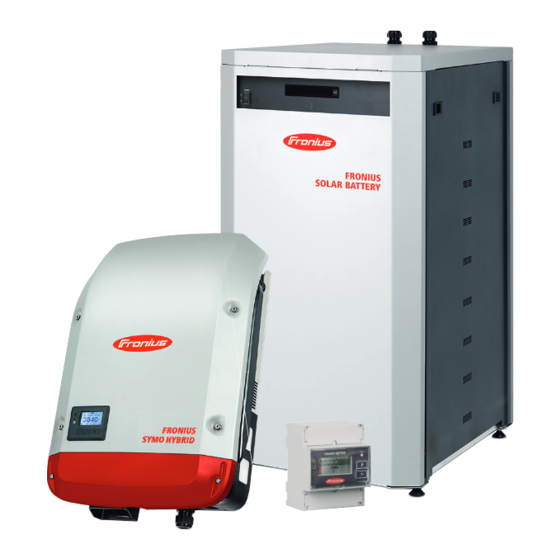
- Page 1 Operating Instructions Fronius Energy Package Operating Instructions 42,0426,0222,EN 024-05052022...
-
Page 3: Table Of Contents
Backup power and energy saving mode Fronius Ohmpilot and backup power mode Energy saving mode General Fronius Solar Battery and Fronius Symo Hybrid switch-off conditions Fronius Symo Hybrid and Fronius Solar Battery switch-on conditions Special case Indicators on the devices and user interfaces... - Page 4 Operation Data communication Data communication area General Controls, connections and indicators on the system monitoring unit Fronius Hybrid inverter Controls and indicators Display Fronius Solar Battery Battery management module Battery module Display Display types Data converter connections Data converter controls and indicators...
-
Page 5: Status Codes - Class
Connecting to Fronius system monitoring via a web browser General remarks Prerequisites Establishing a connection to Fronius system monitoring via a web browser Connecting to Fronius system monitoring established via the Internet and Fronius Solar.web General remarks Functional description Prerequisites Accessing Fronius system monitoring data via the Internet and Fronius Solar.web... -
Page 6: Status Codes - Class
Settings – System overview System overview Settings - Meter General Fronius Smart Meter Connection of the Fronius Smart Meter to Fronius system monitoring Settings – DNO Editor General DNO Editor – IO control Connection example "PSC editor - AUS - Demand Response Modes (DRM)"... -
Page 7: Safety Rules
Safety rules Explanation of DANGER! safety notices Indicates immediate danger. ▶ If not avoided, death or serious injury will result. WARNING! Indicates a potentially hazardous situation. ▶ If not avoided, death or serious injury may result. CAUTION! Indicates a situation where damage or injury could occur. ▶... -
Page 8: Environmental Conditions
Any safety devices that are not fully functional must be repaired by an author- ised specialist before the device is switched on. Never bypass or disable protection devices. For the location of the safety and danger notices on the device, refer to the sec- tion headed "General remarks"... -
Page 9: Emergency Power
Emergency This system is equipped with an emergency power function. This means a backup power power supply is automatically established in the event of a power outage. The emergency power sticker provided with the inverter must be attached to the electrical distributor. -
Page 11: General Information
General information... -
Page 13: Fronius Symo Hybrid
Fronius Symo Hybrid Device concept Device design: Housing cover Inverter Mounting bracket Connection area including DC main switch Data communication area Data communication cover The hybrid inverter converts the direct current generated by the PV modules into alternating current. This alternating current is synchronized with the grid voltage and fed into the public grid. -
Page 14: Proper Use
Fronius Installing components that are not distributed or expressly approved by Fronius Operating the device with a battery that has not been approved by Fronius Operating the equipment with an energy meter that has not been approved by Fronius Fronius shall not be liable for any damage resulting from such action. -
Page 15: Product Registration
You only need to fill out a few details and confirm the registration. Who can register a device? The warranty agreement is concluded between Fronius and the warranty holder (owner of the installed system). For this reason, the system must be registered by the warranty holder using their Solar.web login credentials. - Page 16 Where can I find the serial number for my product? The serial number can be found on the rating plate of the Fronius device. For the Solar Battery, only use the serial number shown in the picture. The serial numbers of the individual battery modules are not relevant.
-
Page 17: Fronius Solar Battery
Battery module (1.2 kWh usable capacity) With the market launch of its new Fronius Energy Package, Fronius is introducing an inverter that can be used to store energy. One of the key components is the Fronius Solar Battery, which contains a lithium-ion rechargeable cell. The Fronius Solar Battery supplements the Fronius hybrid inverter by adding storage func- tionality. -
Page 18: Increase In Storage Capacity
Observe the stipulations of the power supply company concerning energy fed in- to the grid and the operation of storage systems. Increase in stor- The storage capacity of the Fronius Solar Battery can also be increased after age capacity purchase to a maximum capacity of 9.6 kWh of usable energy. - Page 19 Safety symbols – Text of the warning notices: CAUTION! Incorrect handling or failing to observe these notices and the operating instructions is extremely dangerous. It may give rise to thermal/electric- al or fire hazards, thereby resulting in serious injuries. Please read the Operating Instructions carefully while also ensuring compliance with the safety instructions during use! To avoid electric shocks: Do not dismantle or modify the device...
-
Page 20: The Various Operating Modes
Converts the direct current into alternating current. Cannot, however, be used to charge batteries and is not available to provide emergency power. Grid Operating mode: The Fronius hybrid inverter can be used purely as an inverter without a battery Inverter connected to it. -
Page 21: Operating Mode - Inverter Plus Battery
Operating mode To ensure fault-free regulation, parallel operation of several batteries is not per- - Inverter plus mitted. battery To optimise self-consumption in your PV system, you can use a battery as a stor- age system. The battery is connected to the inverter on the DC side. As a result, there is no need for multiple current conversion processes, which results in greater efficiency. -
Page 22: Operating Mode - Inverter Plus Battery And Multiple Smart Meters
Operating mode - Inverter plus battery and mul- tiple Smart Meters Operating mode - inverter with battery, AC- coupled to an- other inverter Operating mode IMPORTANT! In emergency power mode, an increased nominal frequency is - Inverter plus used in order to avoid parallel operation with other generators. battery and emergency To ensure fault-free regulation, parallel operation of several batteries is not per-... -
Page 23: Operating Mode - Inverter Plus Battery, Ohmpilot And Emergency Power Function
Operating mode IMPORTANT! In a hybrid PV system with Fronius Ohmpilot and all the system - Inverter plus features, the Ohmpilot cannot be operated in the event of a power failure for battery, Ohmpi- control-related reasons. Therefore, it makes sense to install the Ohmpilot outside lot and emer- of the emergency power circuit. -
Page 24: Operating Mode - Inverter Plus Battery, Additional Inverter And Emergency Power Function
Service mode SOC value and then kept at this value until service mode is ended manually. The Fronius Symo Hybrid recharges the battery to counteract self discharge and maintain the set Forced re-charging minimum SOC (protection against deep dis- charge). - Page 25 Operating state Description The storage system starts from energy saving Start mode (standby). Only available for the Fronius Solar Battery.
-
Page 26: Emergency Power Mode
If there are additional inverters in the system, these should be installed outside of the emergency power circuit, but within that for the Fronius Smart Meter, see Operating mode - Inverter plus battery, additional inverter and emergency power function on page 24. -
Page 27: Restrictions In Backup Power Mode
More information on energy saving mode can be found in chapter mode on page Fronius Ohmpi- The Fronius Ohmpilot is not suitable for backup power mode. If a Fronius Ohmpi- lot and backup lot is used, it should be installed outside of the backup power circuit (see Oper-... - Page 28 Disable functions that would exceed the power limits in backup power mode: Set measuring of heating rod to manual on the Ohmpilot (under "General - General Settings - Heating 1 - Manual"). Disable the "Legionella prevention (h)" and "Adapt day curve" settings (under "General - General Settings - Heating 1").
-
Page 29: Energy Saving Mode
When the battery is in energy saving mode, the display remains dark. In Sol- ar.web, energy saving mode is indicated by an "i" next to the battery symbol. In the energy balance view, the SOC (State of Charge) of the Fronius Solar Battery is not displayed for the duration of energy saving mode. -
Page 30: Fronius Symo Hybrid And Fronius Solar Battery Switch-On Conditions
The battery is recharged to restore the minimum state of charge or to per- form a calibration. The Fronius Solar Battery is woken up as soon as the Symo Hybrid is generat- ing PV power. This guarantees reliable operation of the battery. -
Page 31: Calibration Charging For The Fronius Solar Battery
The following description of calibration charging is valid from version 1.4.1-12 of the Fronius system monitoring software. Conditions for One charge and discharge cycle of the Fronius Solar Battery corresponds to an starting the cal- energy throughput of 48 Ah per battery module. Calibration charging occurs cyc-... -
Page 32: Calibration Process (Fronius Solar Battery)
Emergency power mode can be started – calibration charging is interrupted Display during As soon as calibration charging starts, it becomes visible in Fronius Solar.web calibration (current and energy balance view) or on the web interface of the Fronius Symo charge (Fronius Hybrid inverter. Solar Battery) - Page 33 0.3 A, 0 A is shown on the display, even though calibration charging continues. In Fronius Solar.web, the SOC value for the entire battery is displayed. On the battery display, the SOC values of the individual battery modules can be viewed.
-
Page 34: Suitable Third-Party Batteries For Fronius Symo Hybrid
Fronius expressly points out that third-party batteries are not Fronius products and that Fronius is not a trader or distributor of these batteries. This means that Fronius accepts no liability for these batteries and cannot offer any kind of war- ranty. - Page 35 * Note for systems with backup power switchover with Fronius Symo Hybrid and BYD Battery-Box Premium HVM 8.3: If there is a power failure, there is no energy available from the PV system and the battery has a low state of charge (SOC typically < 20%), the system may no longer be able to switch to backup power mode.
- Page 36 Switch on the automatic circuit break- er. Set the DC disconnector to the "On" switch position.
-
Page 37: Operation
Operation... -
Page 39: Data Communication Area
Use the mating connector supplied with the inverter to connect to the floating switch contact. System monitoring with WLAN antenna General The inverter is fitted with the WLAN-enabled system monitoring and energy management unit (Fronius Datamanager) as standard. Various functions are included with the Fronius system monitoring, such as:... -
Page 40: Controls, Connections And Indicators On The System Monitoring Unit
Ability to control the inverter via Modbus (TCP) Ability to assign control priorities Ability to control the inverter by means of connected meters (Fronius Smart Meter) Ability to control the inverter via a ripple control signal receiver (e.g. by spe-... - Page 41 Lights up green: Fronius Solar.web connection established Lights up red: Fronius Solar.web connection is required but has not been established Not lit: no Fronius Solar.web connection is required or the option for sending data to Fronius Solar.web has been deactivated Supply LED Lights up green: internal communication system is providing an ad- equate power supply;...
- Page 42 Function I/Os Digital inputs and outputs RS485 Modbus RTU 2-wire (RS485): Modbus data - Modbus data + Int./ext. power supply Internal voltage output 12.8 V input for an external supply voltage >12.8 - 24 V DC (+ 20%) Digital inputs: 0 - 3, 4 - 9 Voltage level: low = min.
- Page 43 Function Modbus termination switch (for Modbus RTU) Internal bus terminator with 120 ohm resistor (yes/no) Switch in "on" position: 120 ohm terminating resistor active Switch in "off" position: no terminating resistor active IMPORTANT! On an RS485 bus, the terminating resistor on the first and last device must be active.
-
Page 44: Fronius Hybrid Inverter
Fronius Hybrid inverter Controls and in- dicators (5) (6) (7) (8) Item Description Display For displaying values, settings and menus Monitoring and status LEDs General status LED Lights up steady: If a status code is being displayed on the monitor (red for error,... -
Page 45: Display
Item Description “Enter” key For confirming a selection The keys operate capacitively. Exposure to water may impair their function. If ne- cessary, wipe the keys dry with a cloth to ensure optimum functionality. Display The display is supplied with power via the AC grid voltage and via the PV and bat- tery side. -
Page 46: Fronius Solar Battery
Fronius Solar Battery Battery manage- ment module LCD display Provides information about the status of a module (charging/discharging, total voltage, total current strength, total remaining capacity, number of connected modules, remaining capacity of each module, voltage/temper- ature etc. of the cell block) -
Page 47: Display Types
Display switching diagram Display overall status Overall of system Connection Display status of indi- vidual modules Modul Nr. 00 Modul .Nr. N Status Status Mode Mode Cell temp Cell temp. Alarm bits Alarm bits Heatsink Press and hold DISP key Press DISP key Nr.N. - Page 48 UNIT Number of connected modules 1 - 16 Version XXXX Status of connected modules In the above example, there are 6 connected modules (no. 00 - no. 05). "Status" display Display Details Display M_NO Number of modules displayed 00 - 15 STAT Module status YX (Y: Current status, X: Previ-...
- Page 49 "Cell Temp., Cycle Count" display Display Details Display M_NO Number of modules displayed 00 - 15 CYCL Number of cycles 0000 - 9999 Average temperature of all cells -99.9 °C to +99.9 °C "Alarm bits" display Display Details Display M_NO Number of modules displayed 00 - 15 ALRM...
-
Page 50: Data Converter Connections
S7 = 0x4 (hex) = 0100 (binary) RS485 terminal Rx422 = off Tx422 = off Data converter The data converter features 8 LEDs, the meaning of which is explained below: LED displays Fronius Solar Bat- Fronius hybrid in- tery verter RS232/422/485 Fieldbus RS232/422/485... - Page 51 Flashing Status OK green/red Lights up red General gateway error (see "Error No." LEDs) Flashing red Data converter is in configuration/test mode "State" LED (Fronius hybrid inverter) Lights up green Initialised and started Flashing green Initialised Flashing green/red Lights up red...
-
Page 52: Navigation At The Menu Level
Navigation at the menu level Activating dis- Press any key play backlighting The display backlighting is activated. There is an option under "Display Settings - Backlighting" in the SETUP menu to set the display backlighting so that it is on all the time or off all the time. Automatic deac- If two minutes pass without any button being pressed, the display backlighting tivation of dis-... -
Page 53: Values Displayed Under The Now Menu Item
Values displayed Output power (W) under the NOW AC reactive power (VAr) menu item Grid voltage (V) Output current (A) Grid frequency (Hz) Solar voltage (V) – Of U PV Solar current (A) – Of I PV Time Date Values displayed Energy fed in (kWh / MWh) under the LOG Energy delivered by the inverter over the period in question... -
Page 54: Menu Items In The Set-Up Menu
Menu items in the Set-up menu Standby Manual activation / deactivation of Standby mode No energy is fed into the grid. The Startup LED will show steady orange. In the display, STANDBY / ENTER are alternately displayed In Standby mode, no other menu item at menu level can be accessed or ad- justed. -
Page 55: Relay (Floating Contact Switch)
WiFi Access Point [not available] Displayed if there is no system monitoring present on the inverter. Relay (floating Status codes (state codes), the status of the inverter (e.g. feeding energy into the contact switch) grid) or Energy Manager functions can be displayed using the floating switch con- tact (relay). -
Page 56: Energy Manager(Under "Relay" Menu Item)
Energy Manager: E-Manager: Further details on the "Energy Manager" function may be found in the "Energy Manager" section. Relay test Function test to determine whether the floating switch contact switches Switch-on point (only if "Energy Manager" function is activated) for setting the effective power limit beyond which the floating switch contact is switched on Factory setting 1000 W... -
Page 57: Time / Date
When choosing the switch-off point, the power consumption of the connected load should be taken into account. When choosing the switch-on point, the weather conditions and anticipated in- solation should also be taken into account. Application example Switch-on point = 2000 W, switch-off point = 1800 W If the inverter is outputting 2000 W or above, then the floating switch contact on the inverter is switched on. -
Page 58: Display Settings
Display settings Setting range Language / Contrast / Illumination Language Set language for display Setting range German, English, French, Dutch, Italian, Spanish, Czech, Slovak, etc. Contrast Set the contrast on the display Setting range 0 - 10 Factory setting Since the contrast is temperature-dependent, it may be necessary to adjust the setting under the "Contrast"... -
Page 59: Fan
Setting range 2 digits, 3 decimal places Factory setting (depends on country setup) CO2 factor Setting the CO2 factor of the energy fed into the grid To check that the fan is working correctly Setting range Test fan #1 / Test fan #2 (depending on the device) Use the "Up"... -
Page 60: Setup Menu Item
SETUP menu item Initial setting The inverter is pre-configured after commissioning has been completely carried out (e.g. using the Installation Wizard) according to the country setup. The SETUP menu item allows the initial settings of the inverter to be changed easily to bring it in line, as closely as possible, with the preferences and require- ments of the user. -
Page 61: Application Example: Setting The Time
The inverter switches from wherever it is on the menu level back to the "NOW" display mode (exception: "Standby" Setup menu item). The display backlighting goes out. The current power of feeding in is displayed. Setting menu Open the desired menu entries, general Use the 'Up' or 'Down' keys to select the desired menu item Press "Enter"... - Page 62 An overview of the values that can be changed is displayed. Use the “Up” or “Down” keys to select “Set time”. Press the “Enter” key. The current time appears. (HH:MM:SS, 24-hour clock), the “tens” digit for the hour will flash. Use the “Up”...
-
Page 63: The Info Menu Item
The INFO menu item Measured values PV ins. Insulation resistance of the photovoltaic system and the storage system Ext. lim. External power reduction in per cent e.g. specified by grid operator U PV Current PV voltage on the terminals even if the inverter is feeding in no power whatsoever GVDPR Grid voltage-dependent power reduction... - Page 64 ON / OFF – Voltage-dependent power reduction GVDPRe Threshold at which the voltage-dependent power reduc- tion begins GVDPRv Reduction gradient used to reduce the power, e.g.: 10% per volt above the GVDPRe threshold Message Activates the sending of an info message via Fronius Solar Net...
-
Page 65: Version
Fault Ride Through: Status – Default setting: OFF If the function is activated, the inverter does not switch off immediately in the event of a short-term AC voltage dip (outside of the limits specified by the grid supplier), but instead continues to feed in power for a defined period. -
Page 66: Switching The Key Lock On And Off
Switching the key lock on and off General The inverter has a key lock function. When the key lock is active, the Setup menu is not accessible, i.e. the setup data cannot be changed accidentally (or maliciously). The code 12321 has to be entered in order to activate / deactivate the key lock. Switching the Press the "Menu"... -
Page 67: The Basic Menu
The Basic menu Accessing the Press the "Menu" key Basic menu The menu level appears. Press the unassigned "Menu / Esc" key 5 times "Access Code" is displayed in the "CODE" menu; the first digit starts flashing. Enter the code 22742: Use the "Plus" and "Minus"... - Page 68 MPP Tracker 1 DC operating mode: MPP AUTO / FIX / MPP USER MPP AUTO: normal operating status; the inverter automatically searches for the ideal operating point FIX: for entering a fixed DC voltage at which the inverter will operate MPP USER: for entering a lower MP voltage above which the inverter will search for its ideal operating point Dynamic Peak Manager: ON / OFF...
-
Page 69: Fronius System Monitoring
Fronius system monitoring... -
Page 71: General
General Fronius system monitoring is a networked datalogger. The Fronius system monitoring web page provides a quick overview of the photo- voltaic system. It can be accessed via a web browser when there is a direct connection or – if configured to support an indirect connection –... -
Page 72: Calculating Data Volumes
The table below provides an overview of the data volume for various configura- tions and time settings (INV = Fronius Symo Hybrid, SM = Smart Meter, BAT = battery module of the Fronius Solar Battery) Data volume per day:... - Page 73 A data volume of approx. 500 kB per hour is required to view the system on Fronius Solar.web or the Fronius Solar.web App. A certain data volume is also required to update the Fronius system monitoring firmware. This data volume depends on the size of the update package and there- fore cannot be considered in the advance data volume calculation.
-
Page 74: General Information For The Network Administrator
255.255.255.0). If you want Fronius system monitoring to send service messages or to transmit data to Fronius Solar.web, you must enter a gateway address and a DNS server address. Fronius system monitoring uses the gateway address for the purpose of establishing an Internet connection. -
Page 75: Using Fronius Solar.web And Sending Service Messages
Solar.access or Fronius Solar.service Ability to access the Datamanager web page Configure the firewall so that data can be sent from the Fronius system monitor- ing IP address to port 49049/UDP of "fdmp.solarweb.com". *) We recommend only allowing access to the web interface of the Fronius sys- tem monitoring function from secure networks. -
Page 76: Installing Fronius System Monitoring - Overview
Starting for the IMPORTANT! Starting up the Fronius system monitoring function for the first first time time is made considerably easier with the Fronius Solar.start app. The Fronius Solar.start app is available in the respective app stores. Or visit https://wizard.solarweb.com... - Page 77 Search for a network with the name "FRONIUS_239.xxxxx" Establish a connection to this network Enter the password 12345678 (Alternatively, connect the end Run the Fronius Solar.start app device and inverter using an Eth- ernet cable.) Enter the following in the browser: http://datamanager 192.168.250.181 (IP address for...
-
Page 78: Information To Help You Work Through The Technician Wizard
Once you have worked your way through the technician wizard, an automatic pro- cess is triggered to calibrate all the components. This involves charging the Fronius Solar Battery fully. After that, the system automatically starts in the set operating mode. -
Page 79: Testing Backup Power Mode
A battery state of charge of over 30% is recommended when in test mode. A description of how to perform the test operation can be found in the chapter "Backup power checklist" of the document "Fronius Energy Package - Examples of backup power switchover". -
Page 80: Connecting To Fronius System Monitoring Via A Web Browser
General remarks A connection to Fronius system monitoring via a web browser is the ideal choice if there are lots of PC users who need to access the latest system values over the same LAN (e.g. company networks, schools, etc.). -
Page 81: Connecting To Fronius System Monitoring Established Via The Internet And Fronius Solar.web
Fronius Solar.web” is set to “Yes” under “Fronius Solar.web” in the settings for Fronius system monitoring. In order for archive data to be accessed in Fronius Solar.web, “Send archive data to Fronius Solar.web” must be set to “daily” or “hourly” for Fronius sys- tem monitoring. Accessing Froni- To use Fronius Solar.web for the purpose of accessing current data and archive... -
Page 83: Current Data, Services And Settings Offered By Fronius System Monitoring
Current data, services and settings offered by Fronius system monitor-... -
Page 85: The Fronius System Monitoring Web Page
Overview of recent status codes System information, network diagnostics, firmware update The Settings menu The Settings When you click "Settings", the Settings menu appears on the Fronius system menu monitoring web page. The "Settings" menu is where you configure Fronius system monitoring. -
Page 86: Additional Setting Options
Additional set- On the Fronius system monitoring web page, the following additional setting op- ting options tions are available on the top right-hand side: System information: Datalogger ID, software version, hardware version, Fronius Solar.web connection Help: Commissioning the LAN Commissioning the WLAN... -
Page 87: Services - System Information
Services – System information System informa- The system information page contains various information about the system. tion Additionally, there are the following buttons: "Datalogger restart" For restarting the Datamanager / system monitoring "Reset to factory settings" button with the selection options: "All settings except for the network"... -
Page 88: Services - Network Diagnostics
Services – Network diagnostics Network dia- Under Services / Network diagnostics, you will find various functions that are gnostics useful for diagnosing and resolving network problems. You can execute ping and traceroute commands. Ping command A ping command allows you to check whether a host can be reached and how long the data transfer process takes. -
Page 89: Services - Firmware Update
Services – Firmware update General The firmware of the Fronius system monitoring datalogger can be updated under Services / Firmware update. A firmware update can be performed via a LAN or over the Web. Searching for IMPORTANT! An Internet connection is required to use the “Automatic update updates auto- search”... -
Page 90: Services - Starting The Wizard
Starting the wiz- You can access and run the setup wizard again by selecting "Open wizards". SOLAR WEB WIZARD For connecting the system to Fronius Solar.web and Fronius apps for mobile devices TECHNICIAN WIZARD (for trained personnel or specialists only) -
Page 91: Settings - General
Settings – General General Under "Yield", you can enter the charge rate per kWh ("Feed-in tariff"), the cur- rency and the procurement costs per kWh ("Grid supply tariff") for calculating the yield. The yield figure is displayed in the current general view. Under "System time", you can enter the date, hour and minutes. -
Page 92: Settings - Passwords
Settings – Passwords General remarks Access to Fronius system monitoring is controlled by assigning passwords. There are 3 different types of password available for this purpose: The administrator password The service password The user password Passwords Administrator password User name = admin The administrator password is set during the commissioning process and grants the user read access and the right to change settings. -
Page 93: Settings - Network
As a result, the connection to the Datamanager (system monitoring) can be established using the name instead of the IP address. For example: Host name = sample_system, domain name = fronius.com The Datamanager (system monitoring) can be reached via the address "sample_system.fronius.com". - Page 94 The Datamanager (system monitoring) serves as an access point. A PC or smart device connects directly with the Datamanager (system monitoring). It is not possible to connect to the internet.
-
Page 95: Settings - Fronius Solar.web
Settings – Fronius Solar.web Fronius Sol- You can use the Fronius Solar.web menu item to establish a direct connection to ar.web Fronius Solar.web. The storage system interval selected for the fields "Inverter Query Cycle" and "Fronius Sensor Cards Query Cycle" affects the required storage capacity. -
Page 96: Settings - Io Mapping
Settings – IO mapping General This menu item allows you to configure the properties of the inverter's individual inputs and outputs (I/O). You can only select those settings that are supported by the system concerned (which are determined by the functionality of the sys- tem and how it has been configured). - Page 97 IMPORTANT! To control the inverter via DRM, a Fronius DRM interface (item number 4,240,005) is required in the inverter. Installation is described in the Installation Instructions for the Fronius DRM interface. The Installation Instructions for the Fronius DRM interface are avail- able on the Fronius homepage at the following link: http://www.fronius.com/QR-link/4204102292...
-
Page 98: Energy Storage Device
The remote control capability of the inverter always relates to the nominal device output. IMPORTANT! If no DRM control (DRED) is connected to the Datamanager and the "AUS - Demand Response Mode (DRM)" function is activated, the inverter switches to standby mode. Energy storage The pin for activating the energy storage device can be selected here. -
Page 99: Settings - Load Management
Settings - load management Load manage- Energy management controlling priorities ment If additional components (e.g. battery, Ohmpilot) are available in the system, the priorities can be set here. Devices with a higher priority are activated first, fol- lowed by the others if surplus energy is available. Load management Up to four different load management rules can be defined. -
Page 100: Settings - Push Service
This function allows you to export current and log data to an external server in different formats or using different protocols. For further information about the push service function, please see the following Operating Instructions: http://www.fronius.com/QR-link/4204102152 42,0410,2152 Fronius Push Service... -
Page 101: Settings - Modbus
Settings – Modbus General remarks With a web browser, you can use the Fronius system monitoring web page to make settings for the Modbus connection that are not accessible via the Modbus protocol. Further informa- For further information about the Modbus function, please see the following Op-... -
Page 102: Restricting Control
If inverter control is to be limited to one or more devices, use this field to enter the IP addresses of the one(s) that is/are allowed to send commands to the Fronius Datamanager. Use commas to separate multiple entries. Examples: One IP address: 98.7.65.4 - Inverter may only be controlled by IP address... -
Page 103: Settings - Energy Manager
Own consumption optimization ment The Fronius hybrid inverter always controls the system by adjusting it in line with the target value set at the metering point. In the "automatic" operating mode (factory setting), an adjustment is made to 0 W at the feed-in point (maximum self-consumption). - Page 104 2000 W TARGET: 0W 1500 W 500 W 1500 W Example involving battery system with a second producer within the home PV system to Fronius Symo Hybrid: 1000 W Second producer in home network: 2000 W Household consumption: 500 W...
- Page 105 1500 W 500 W 2500 W Example involving battery system plus a second producer within the home (with AC max. limiting) PV system to Fronius Symo Hybrid: 1000 W Second producer in home network: 2000 W Household consumption: 500 W Target value set at feed-in point: Max.
- Page 106 Calibration charging (only for Fronius Solar Battery) At regular intervals, the Fronius hybrid inverter automatically charges the Froni- us Solar Battery until it is full for the purpose of calibrating all the components. This process can be started manually here.
-
Page 107: Permitted Battery Control Parameters
tem. Depending on the insolation conditions and size of the systems concerned, the charging process can take a very long time. If the "permit battery charging from DNO grid" setting is activated, the calibra- tion charging process is performed by drawing a constant current from the photovoltaic system and the distribution network operator's grid. - Page 108 Specifying the charging range It is possible to define a charging range with a min. and max. charging limit. In this case, it is not possible for the battery to discharge. Discharging Discharge / charge Charging limit limit Min. char- Max.
-
Page 109: Pv Power Reduction
The battery control parameters make the generated energy as optimally usable tion as possible. However, situations may arise in which PV energy cannot be fully used due to battery control parameters. Example Fronius Symo Hybrid 3.0-S: 3000 W (max. output power) Fronius Solar Battery 7.5... - Page 110 In this case, the inverter would need to reduce the PV power to 0 W, as the out- put power of the Fronius Symo Hybrid 3.0-S is max. 3,000 W and the device is already fully utilised through the discharging.
-
Page 111: Settings - System Overview
Battery If a battery is connected to the Fronius hybrid inverter, it must be activated here. This setting can only be made when there is an active connection to a battery. If you are unable to make this setting, check whether the battery is switched on and whether the data connection has actually been established. - Page 112 If the function is activated, the inverter remains permanently connected to the grid so that energy can be drawn from other producers at any time. Once the meter is connected, its position must be configured in the Fronius Datamanager. Several Fronius Smart Meters can be installed in the system. A different address needs to be set for each Smart Meter.
-
Page 113: Settings - Meter
Fronius Smart If the Fronius Smart Meter is selected as the meter, the meter position needs to Meter be configured in the "Settings" field. "Meter position" at "feed-in point" (1a) The meter measures the amount of power and energy fed in. - Page 114 RS 485 Symo Hybrid DT/PE INPUT Rx / Tx GND 9 11 120 Ω LOAD X X X Fronius Smart Meter 50kA-3 Fronius Smart Meter 50kA-3 Fronius Smart Meter 50kA-3 INPUT INPUT 1N1E 3-2E (1-2) CURRENT CURRENT 6A 6A 6A...
-
Page 115: Settings - Dno Editor
"Export" button - Click this to save the rules separately in *.fpc format Connection ex- Ripple control signal receiver with 3 relays, for effective power limiting ample Ripple control signal receiver with 3 relays, for power factor limiting Fronius system monitoring I/Os Consumers (e.g. signal lamp, signal relay) -
Page 116: Psc Editor - Aus - Demand Response Modes (Drm)
If the distance between the Fronius system monitoring datalogger and the ripple control signal receiver exceeds 10 m, a shielded cable is recommended. -
Page 117: Dno Editor - Control Priorities
Modbus data on the system monitoring datalogger. With the Fronius Symo Hybrid, any PV power that is not allowed to be fed into the grid is used to charge the battery instead so that it does not go to waste. Dy- namic power reduction is only activated if the battery is full or cannot be charged for some other reason. -
Page 118: Dno Editor - Battery Charge
Max. grid power feed: 60% Example 2 If there are two Smart Meters in the feed-in branch, the Datamanager and the Fronius Datamanager (hybrid) in Solar.web cannot be shown combined in one PV system. Two individual PV systems must be created. - Page 119 (inverter 1) > P (hy- AC nom AC nom brid) Example: 7 kW > 5 kW AC nom > Two Smart Meters are required for the inverters. These must be in- stalled at the feed-in point. Hybrid system overview (web page): Settings –...
-
Page 120: Settings - Battery
Service mode allows you to replace and extend the battery modules and is also intended for test purposes. When this mode is activated, the Fronius Solar Battery is charged or discharged by means of a 10 A current or with the maximum inverter power, regardless of any other parameter settings. -
Page 121: Troubleshooting And Maintenance
Troubleshooting and maintenance... -
Page 123: Fronius Symo Hybrid
Fronius Symo Hybrid Status code dis- The inverter performs a system self-diagnosis that automatically detects many play faults that may occur and shows them on the display. This means you are promptly made aware of malfunctions in the inverter or the photovoltaic system, or of any installation or operating faults. - Page 124 Code Description Behaviour Remedy Emergency power overload Emergency power mode is interrupted. The inverter Emergency power short- Check emergency power attempts to start emer- circuit circuit; if this status code gency power mode three keeps recurring, contact Status code 143 or 144 times;...
-
Page 125: Status Codes - Class
The inverter repeats its sink; **) startup routine. *) If the status code is displayed all the time: Notify a Fronius-trained service technician. **) Fault is rectified automatically. If this status code keeps recurring, contact your system fitter Status codes –... - Page 126 Code Description Behaviour Remedy Hardware ID problem The inverter will auto- Unable to communicate with sys- matically attempt to tem monitoring connect again and, if Update inverter firm- Unable to communicate with the possible, will resume ware; *) power stage set feeding energy into the grid.
-
Page 127: Status Codes - Class
*) *) If the status code is displayed all the time: Notify a Fronius-trained service en- gineer. **) If this status code keeps recurring, contact your system engineer. Status codes –... - Page 128 Fault rectified automatically; **) ures message is shown on the display. *) If the status code is displayed all the time: notify a Fronius-trained service en- gineer **) If this status code keeps recurring, contact your system engineer.
- Page 129 PC board has been re- grid. placed) *) If the status code is displayed all the time: Notify a Fronius-trained service en- gineer. **) Fault is rectified automatically. If this status code keeps recurring, contact your system engineer.
- Page 130 *) If the status code is displayed all the time: Notify a Fronius-trained service en- gineer. Status codes – Class 9 status codes only affect the Fronius Solar Battery. These are only dis- Class 9 played on the system monitoring page and are not shown on the inverter display.
- Page 131 Error message out- put, operation resumes Communication error Battery operation not Check wiring; **) between Fronius Symo Hy- possible, feed-in re- brid and Fronius Solar Bat- sumes tery Communication error Battery operation not Displayed in standby mode, if between Fronius Symo Hy-...
-
Page 132: Customer Service
Fronius Smart possible, feed-in re- Meter sumes *) If the status code is displayed all the time: Notify a Fronius-trained service technician **) If this status code keeps recurring, contact your system engineer Class 10 - 12 1000 - 1299- Provide information on the status of the internal processor pro-... -
Page 133: Fronius Solar Battery
Fronius Solar Battery Status code dis- The storage system performs a system self-diagnosis that automatically detects play many faults that may occur. These are indicated on the display or via LEDs. This means you are promptly made aware of malfunctions in the storage system, or of any installation or operating faults. -
Page 134: Undefined Operating Statuses
LED8 LED4 LED2 LED1 Error no. Display or ID Reserved Hardware fault EEROM fault Internal memory error Fieldbus hardware fault Script error Reserved RS transmission buffer overflow RS receiver buffer overflow RS timeout General fieldbus error Parity error or stop bit error (frame check) Reserved Fieldbus configuration error... - Page 135 the inverter on both the DC and AC sides. If this does not resolve the error, noti- fy Customer Services. Whenever an error message of any kind appears on the battery display: Disconnect the inverter on the DC side and isolate it from the grid on the AC side.
-
Page 137: Appendix
Appendix... -
Page 139: Technical Data
Technical data Fronius Symo Hybrid 3.0-3-S 4.0-3-S 5.0-3-S Input data PV input power 5 kW 6.5 kW 8 kW MPP voltage range 190 - 800 V DC 250 - 800 V DC 315 - 800 V DC Max. input voltage 1000 V DC (at 1000 W/m²/ -10 °C in an open cir-... - Page 140 Fronius Symo Hybrid 3.0-3-S 4.0-3-S 5.0-3-S Permitted ambient temperature -25 °C - +60 °C Permissible humidity 0 - 100 % EMC emission class DC / AC overvoltage category Pollution degree Noise emission 59.5 dB(A) ref. 1pW Protection devices DC isolation measurement...
-
Page 141: System Monitoring
Fronius Solar Battery Battery 9.0 Battery 10.5 Battery 12.0 Electrical parameters Usable capacity 7.2 kWh 8.4 kWh 9.6 kWh Cycle stability 8000 Voltage range 240 - 345 V 280 - 400 V 320 - 460 V Nominal charging power 4800 W... -
Page 142: Explanation Of Footnotes
Guaranteed by the electrical configuration of the inverter Current peak when switching on the inverter Applicable Fronius hybrid inverter: standards and guidelines CE mark The devices conform to all the requisite and relevant standards and guidelines that form part of the relevant EU directive, and are therefore permitted to dis- play the CE mark. - Page 143 Fronius Solar Battery: IEC/EN 62133 EN 50178 (1997) EN 61000-6-2:2005 EN 61000-6-3:2007 + A1:2011 EN 62208 EN 62311:2008 FCC Part 15 Subpart B:2012 Class B IEC 60730-1 (Fourth Edition) 2010 (H.7, H.11.12, H.27.1.2) UN 38.3 60730-1 2011 (H.7, H.11.12, H.27.1.2)
-
Page 144: Warranty Terms And Conditions, And Disposal
Detailed, country-specific warranty terms are available on the internet: facturer's war- www.fronius.com/solar/warranty ranty To obtain the full warranty period for your newly installed Fronius inverter or storage system, please register at: www.solarweb.com. Disposal Waste electrical and electronic equipment must be collected separately and re- cycled in an environmentally-friendly way, in accordance with the European Dir- ective and national legislation.
Need help?
Do you have a question about the Energy Package and is the answer not in the manual?
Questions and answers