Advertisement
Quick Links
INSTRUCTION SHEET - HS6B Series
INSTRUCTION SHEET
Original Instructions
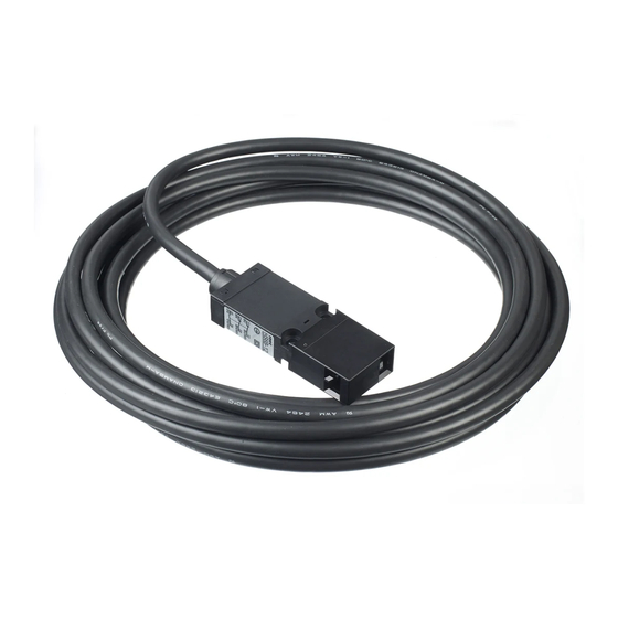
Safety Switch
HS6B Series
Confirm that the delivered product is what you have ordered.
Read his instruction sheet to make sure of correct operation.
S A F E T Y P R E C A U T I O N S
In this operating instruction sheet, safety precautions are categorized to Warning and
Caution:
WARNING
Warning notices are used to emphasize that improper operation may cause severe
personal injury or death.
CAUTION
Caution notices are used where inattention might cause personal injury or damage to
equipment.
1
Type
Safety switch
Actuator
HS6B-11B01
HS9Z-A61
Contact Configuration
Cable Length
11:1NC-1NO
01:1m
02:2NC
03:3m
12:2NC-1NO
05:5m
03:3NC
Note : Select an actuator that moves in the direction required by the hinged door and
safety switch.
2
Specifications and Ratings
Applicable Standards
EN ISO / ISO14119, IEC60947-5-1, EN60947-5-1
GS-ET-15, UL508, CSA C22.2 No.14 GB14046 5
Standards for Use
IEC60204-1/ EN60204-1
Interlocking device Type
Type 2 Interlocking device
/ the level of coded
/ low level coded actuator (EN ISO / ISO14119)
Applicable Directives
Low Voltage Directive, Machinery Direc ive
Operating
Operating Temperature
-25 to +70°C (no freezing)
Condition
Operating Humidity
45 to 85%RH (no condensation)
Storage Temperature
-40 to +80°C (no freezing)
Pollution Degree
3 (Inside2)
Altitude
2000m maximum
Impulse wi hstand voltage ‹Uimp›
4kV
Rated Insulation voltage ‹Ui›
300V
Thermal Current ‹Ith›
2.5A
Contact Ratings
( Reference Values )
‹Ue, Ie›
Electric Shock Protec ion Class
Class II (IEC61140)
Operating Frequency
1200 opera ions/hour
Operating Speed
0 05 to 1.0 m/s
B10d
2,000,000 (EN ISO 13849-1 Annex C Table C.1)
Mechanical Durability
1,000,000 operations minimum (GS-ET-15)
Electrical Durability
100,000 operations min. (AC-12 250V•1.5A)
1,000,000 operations min. (AC/DC 24 100mA)
(1,200 operations / hour)
Shock Resistance
Operating Extremes: 300m/s
Vibration Resistance
Operating Extremes: 5 to 55 Hz, half amplitude 0.5mm
Damage Limits: 30 Hz, half amplitude 1 5 mm
Direct Opening Travel
8 mm minimum
Direct Opening Force
60 N minimum
Contact Resistance
300 mΩ maximum
Degree of Protection
IP67 (IEC60529)
Conditional short circuit current
50A (250V)
Short-Circuit Protec ive Device
250V AC,10A fast acting type fuse
Weight
Approx. 120g (at HS6B-03B01)
* Make sure that a fast acting fuse for short-circuit protection trips before overheating of the wires.
Ratings approved by safety agencies
(1) TÜV ra ing
(2) UL, c-UL rating
AC-15 240V/0.75A
C300 0.75A, 240V ac, Pilot Duty
DC-13 250V/0.27A
Q300 0.27A, 250V dc, Pilot Duty
DC-13 30V/2.3A
(4) KOSHA rating
AC-15 240V/0.75A
DC-13 250V/0.27A
* In order to verify if the product
you are interested in is certified
with the S mark, please check
the following section on our
website: "List of type numbers
certified with the S mark"
61:Straight(Mainly for sliding doors)
62:L-shaped(Mainly for hinged doors)
65:Horizontal / Vertical Adjustment(Note)
66:Horizontal / Vertical Adjustment(Note)
30V
Resistive load(AC-12)
-
AC
Inductive load(AC-15)
-
Resistive load(DC-12)
2.5A
DC
Inductive load(DC-13)
2.3A
, Damage Limits: 1,000m/s
2
(Initial value, at cable length 1m)
*
(3) CCC rating
AC-15 240V/0.75A
DC-13 30V/2.3A
Safety Switch
3
Mounting Examples
Install the safety switch on the immovable machine or guard,
and install the actuator on the movable door. Do not install both
safety switch and actuator on the movable door, otherwise
※
failure will occur.
Note : When inserting an actuator into the slot, make sure to
arrange the
on the right.
Minimum Radius of Hinged Door
When using the safety switch for a hinged door, the minimum radius of the applicable
door is shown in the following figures.
When the center of the hinged door is
on the extension line of the actuator
mounting surfase.
• When using L-shaped actuator (HS9Z-A62)
HS9Z-A62
Door
Hinge
• When using angle adjustable actuator (HS9Z-A65/HS9Z-A66)
• When using angle adjustable actuator (HS9Z-A65/HS9Z-A66)
(Horizontal Adjustment)
HS9Z-A65
HS9Z-A66
(Vertical Adjustment)
HS9Z-A65
HS9Z-A66
125V
250V
2.5A
1.5A
1.5A
0.75A
Note: The figures shown above are based on the condition that the actuator enters
1.1A
0 55A
and exits the actuator entry slot smoothry when the door is closed or opened.
0.55A
0 27A
Since there may be deviation or dislocation of the hinged door, make sure of
correct operation in the actual application before installation.
Actuator Mounting Reference Position
As shown below, the mounting reference position of the actuator inserted into the
safety switch is: The actuator stop touches the safety switch lightly.
Note: After mounting the actuator, remove the actuator stop from the safety switch.
Safety Switch
2
Actuator Stop
HS9Z-A61
Actuator
Actuator Mounting Tolerance
• Mounting tolerance of the actua-
tor is 1.0mm from the center of
the actuator to up, down, right,
and, left.
• Make sure the actuator can be
inserted into the entry slot without
any issue.
shapes in the same direction, as shown
When the center of the hinged door
is on the extension line of the contact
surface of actuator and safety switch.
Door
Hinge
Door Hinge
LABEL
Door Hinge
Door Hinge
LABEL
Door Hinge
Door Stop
Door Stop
±1.0mm
±1.0mm
2016.08
B-1905-1(0)
Door
Door
Hinge
Hinge
Door Hinge
LABEL
Door Hinge
Door Hinge
LABEL
Door Hinge
Safety Switch
Actuator Stop
HS9Z-A65, A66
Actuator
Safety Switch
Center
( 1 / 4 )
Advertisement

Related Manuals for IDEC HS6B Series


Summary of Contents for IDEC HS6B Series
- Page 1 INSTRUCTION SHEET - HS6B Series 2016.08 Safety Switch B-1905-1(0) Mounting Examples Install the safety switch on the immovable machine or guard, and install the actuator on the movable door. Do not install both INSTRUCTION SHEET safety switch and actuator on the movable door, otherwise ※...
- Page 2 CAUTION • The identification of wire is made by the color and white line printed on the wire. • HS6B Series Safety Switches are Type 2 low-level coded interlocking devices (EN Colored Insulator ISO / ISO14119). The following system installation & mounting instructions are EN Color of Insulator ISO / ISO14119 requirements to prevent function failure from the interlock switch.
- Page 3 INSTRUCTION SHEET - HS6B Series 2016.08 Safety Switch B-1905-1(0) Example of wiring Diagram realizing Safety Category Example of a circuit diagram for Safety Category 3 Example of a circuit diagram for Safety Category 4 (attainable PL = d) (attainable PL = e) (Condition 1: To apply he fault exclusion of mechanical structural parts including he actuator →...
- Page 4 2-6-64 Nishimiyahara Yodogawa-ku, Osaka 532-0004, Japan EU Authorized Representative: IDEC Elektrotechnik GmbH Heselstuecken 8, D-22453 Hamburg, Germany DECLARATION OF CONFORMITY We, IDEC CORPORATION 2-6-64, Nishimiyahara Yodogawa-ku,Osaka 532-0004, Japan declare under our sole responsibility that the product: Description: Safety Switch Model No: HS6B to which this declaration relates is in conformity with the EC Directive on the following standard(s) or other normative document(s).