
Related Manuals for ICPDAS RS Series


Summary of Contents for ICPDAS RS Series
- Page 1 RS Series User Manual Industrial Redundant Ring Switch Version 1.2 This document applied to models of RS-405/405F/405A/405AF/408/408A, RSM-405/405F/405-R/405AF/408/408A...
-
Page 2: Revision History
Industrial Redundant Ring Switch – RS Series User Manual Revision History Revision Date 2006/07/01 2012/03/22 2021/11/11 TDRS4050601... -
Page 3: Copyright & Trademarks
Industrial Redundant Ring Switch – RS Series User Manual Copyright & Trademarks All rights reserved. No part of this publication may be reproduced, stored in a retrieval system, or transmitted in any form or by any means, whether electronic, mechanical, photo copying, recording or otherwise, without the prior written permission of the publisher. -
Page 4: Disclaimer
Industrial Redundant Ring Switch – RS Series User Manual Disclaimer Limited Warranty All products manufactured by ICP DAS are warranted against defective materials for a period of one year from the date of delivery to the original purchaser. During this period, if a customer is unable to resolve a product problem with ICP DAS Technical Support, a Return Material Authorization (RMA) will be issued. -
Page 5: Preface
For automation and control engineers who have been forced into this IT domain, they really don't want to get too involved with the idiosyncrasies and maintenance of Ethernet networks. To satisfy these, the RS Series Switch provides you a rugged, fault-tolerant, plug and play solution. ICP DAS industrial Switch Series... -
Page 6: Table Of Contents
Industrial Redundant Ring Switch – RS Series User Manual Contents Revision History..................i Copyright & Trademarks................ii Disclaimer....................iii Limited Warranty.......................iii Standards .........................iii Warning........................iii Safety........................iii Preface......................iv ICP DAS industrial Switch Series................iv How to Use this manual....................iv Contents....................v Acronyms ....................1 Introduction....................4 Ethernet Switch......................5 Industrial Ethernet..................... - Page 7 Industrial Redundant Ring Switch – RS Series User Manual Master LED keep on Flashing Service Information..................30 On-line support ....................... 30 Contact Worldwide....................30 Appendix A....................a Glossaries......................... a Appendix B....................d Specifications......................d Appendix C....................h Modbus Table......................h Appendix D....................i Console Command Reference .................. i Appendix E....................v...
-
Page 8: Acronyms
Industrial Redundant Ring Switch – RS Series User Manual Acronyms Acronym for Asynchronous Transfer Mode, a high performance networking technology based on the switching of fixed length, 53 byte cells. ATM switching supports the switching of voice, video, and data;... - Page 9 Industrial Redundant Ring Switch – RS Series User Manual capabilities, and the logic and timing necessary to provide a standard EIA/TIA or CCITT interface. Converts signals between those used at the DTE's serial interface and bipolar signals used on the digital network.
- Page 10 Industrial Redundant Ring Switch – RS Series User Manual Acronym for Pulse-Coded Modulation, a means of converting analog to digital form. RING Path or channel; usually electrical, where devices along the path receive transmissions sequentially from one device to the next along the ring.
-
Page 11: Introduction
Unlike other existing ring switch or managed Ethernet switch on the market, the RS Series is much more easy to use and absolutely free of software setting. After unpacking from the shipping case, it just takes one or two dip or rotary switch to make it work. -
Page 12: Ethernet Switch
Industrial Redundant Ring Switch – RS Series User Manual Ethernet Switch Ethernet is an ideal medium to transport large volumes of data, at speed, across great distances. Previously, multiple networks carrying specific protocols were installed side by side to carry out unique tasks. This inevitably led to project costs increasing as additional fiber optic or copper cables were installed to deal with the increasing volume of data. - Page 13 30 seconds to detect and recover from the fault – far to long for critical applications! ICP DAS RS Series incorporate propriety protocols that enable multiple Switches to be placed into a redundant ring. A single Switch, configured as the network focal point will monitor, detect and recover from a fiber or copper link failure within approximately 50mS –...
-
Page 14: Industrial Fiber Optic
Industrial Redundant Ring Switch – RS Series User Manual It is likely that these people will not be fully trained on Ethernet and the protocols that are in operation, nor will they fully understand the principles of SNMP etc. However, with a fault contact, fault LED‟s and graphical interface implemented they have a multi-level... -
Page 15: Industrial Vs. Commercial
At ICP DAS, our goal is to meet the demanding requirements of industrial communication networks. Our industry standard, RS Series of industrially hardened fiber optic communication products addresses these issues and provides you with optimal solutions for your factory automation and process control needs. -
Page 16: Appearance
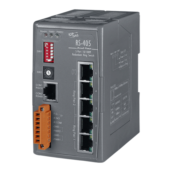
Industrial Redundant Ring Switch – RS Series User Manual Appearance RS Series come with three form factors. One is stand alone with industrial plastic case. The second one is stand alone with aluminum Dimensions case. And the other is modulized for ICPDAS PAC Series controllers Front Panel with industrial plastic case. -
Page 17: Dimensions(Units:mm)
Industrial Redundant Ring Switch – RS Series User Manual Dimensions(Units:mm) TDRS4050601... - Page 18 Industrial Redundant Ring Switch – RS Series User Manual TDRS4050601...
- Page 19 Industrial Redundant Ring Switch – RS Series User Manual Front Panel RS(M)- 405/408 series Master switch LED indicator Power 1 LED indicator Power 2 LED indicator Switch j umper block 1. Ring / Normal Switch selecting jumper 2. Reset to default jumper 3.
- Page 20 Industrial Redundant Ring Switch – RS Series User Manual RS(M)-405F series Master switch LED indicator Power 1 LED indicator Power 2 LED indicator Switch j umper block 1. Ring / Normal Switch selecting jumper 2. Reset to default jumper 3. Primary/Secondary Switch setting jumper 4.
- Page 21 Industrial Redundant Ring Switch – RS Series User Manual RSM-405-R series Terminal block Master switch LED indicator Power 2 LED indicator Power 1 LED indicator Switch j umper block Ring / Normal Switch selecting jumper Rotate jumper block Reset to default jumper...
- Page 22 Industrial Redundant Ring Switch – RS Series User Manual On Case Quick Guide The simple description of DIP and Rotate jumpers setting value, Quick Config Guide, has been printed on both right and left hand side of front panel. After acquainted with RS Series features, field engineers could deploy switches quickly by referencing Quick Config Guide.
-
Page 23: Rotary Switch (Sw2)
Industrial Redundant Ring Switch – RS Series User Manual DIP Switch (SW1) SW1 : DIP Switch Configuration State Jumper Redundancy mode Tradition mode Normal State Default Setting Primary Switch Secondary Switch Ring Protocol STP Protocol Disable Ring Pair 2 Enable Ring Pair 2... -
Page 24: Hardware Installation
Industrial Redundant Ring Switch – RS Series User Manual Hardware Installation For hardware installation, we provide both easy DIN rail mounting and wall mounting modes. DIN-Rail Mounting Installation Overview Wall-Mounting Installation Connecting Input Power RS Series support redundant power, output relay and enhanced isolation to make device much robust. -
Page 25: Din-Rail Mounting Installation
Industrial Redundant Ring Switch – RS Series User Manual DIN-Rail Mounting Installation With ICPDAS patent DIN-Clip design, DIN-Rail mounting installation becomes very easy. ® Following 3 steps completes installation. ➊ Pull the down rail clip out. Up Clip Down Clip Push &... -
Page 26: Wall-Mounting Installation
Industrial Redundant Ring Switch – RS Series User Manual Wall-Mounting Installation With ICP DAS patent DIN-Clip design, Wall-Mounting installation becomes very easy. ® Following 2 steps completes installation. Pull out ➊ Pull out Pull all wall mounting clip out. ➋... -
Page 27: Connecting Input Power
Industrial Redundant Ring Switch – RS Series User Manual Connecting Input Power IMPORTANT: It is good practice to turn off input and load power, and unplug the power terminal block before making wire connections. Otherwise, your screwdriver blade can inadvertently short your terminal connections to the grounded enclosure. -
Page 28: Connecting Output Relay
Industrial Redundant Ring Switch – RS Series User Manual Connecting Output Relay The diagram of output relay: ➊ Identify R.NO and R.COM contacts on terminal block. ➋ Insert the relayed device such as a light bulb or a buzzer pair of wire, and fastening the terminal screws to prevent the wires from coming loose. -
Page 29: Connecting Ethernet Ports
Industrial Redundant Ring Switch – RS Series User Manual Connecting Ethernet Ports RS Series includes all RJ-45 ports with automatic MDI/MDI-X crossover, and automatic 10/100Mbps data rate sensing for 10Base-T or 100Base-TX connections. Automatic MDI/MDI-X crossover allows you to connect to other switches, hubs, or workstations, without regard to using straight-through or crossover cabling. -
Page 30: Connecting Fiber Ports (Only For Models With Fiber Port)
Industrial Redundant Ring Switch – RS Series User Manual Connecting Fiber Ports (only for models with fiber port) The automatic MDI/MDI-X crossover function does not apply to fiber connections, as these must be crossed over manually. To connect the fiber port on one switch to the fiber port of another switch, simply cross-connect the transmit channel at each end to the receive channel at the opposite end as illustrated in the figure below. -
Page 31: Configuration
Industrial Redundant Ring Switch – RS Series User Manual Configuration This chapter provide basic techniques to form a redundant ring on your demand. One Ring Topology Overview Two Rings Coupling Two Rings Coupling with To successfully form a robust industrial Ethernet network, the Two Phase Recovering designing of network pattern is the most important stage. -
Page 32: One Ring Topology
At the moment of any connection failure, the focal point will activates the Redundant Path and fire alarm to output relay. Backup Path Active Path Broken RS Series come with 2 ring pair by default. A ring pair can form a ring with other network devices as below: TDRS4050601... -
Page 33: Two Rings Coupling
Industrial Redundant Ring Switch – RS Series User Manual Two Rings Coupling As a ring network is a small group of switches by geography, functionalities, or subsystem, 2 or more rings could be coupled together to form a whole picture of industrial network for an integrated system. -
Page 34: Two Rings Coupling With Two Phase Recovering
Industrial Redundant Ring Switch – RS Series User Manual Two Rings Coupling with Two Phase Recovering Redundant coupling gives one more chance to keep connection alive when any connection between 2 rings has been broken. It is much safe than Single Coupling, but it takes 3 more switches to form Redundant Coupling. -
Page 35: Troubleshooting
Industrial Redundant Ring Switch – RS Series User Manual Troubleshooting Overview This chapter includes some information for general troubleshooting No Power to the Switch as follows: No Link Light on a Switch Port No Power to the Switch Master LED Keep on... -
Page 36: No Power To The Switch
Industrial Redundant Ring Switch – RS Series User Manual No power to the switch. · Check for faulty power cord. · Check for loose or broken power connections. · Check connections to ensure the power and ground are attached to the correct terminals. -
Page 37: Service Information
Industrial Redundant Ring Switch – RS Series User Manual Service Information We sincerely hope that you never experience a problem with any ICP DAS product. If you do need service, call ICP DAS at 886-3-5973366 and ask for Applications Engineering. -
Page 38: Glossaries
Industrial Redundant Ring Switch – RS Series User Manual Appendix A Glossaries ANSI X3T9 Commonly referred to as FDDI. A local area network protocol that operates at 100Mbps. Asynchronous Having a variable time interval between successive data or information in the form of characters, operations, events. - Page 39 Industrial Redundant Ring Switch – RS Series User Manual Full Duplex A communication method where both ends can transmit and receive simultaneously. Half Duplex A communication method where one end transmits while the other end receives, then reverses the process.
- Page 40 Industrial Redundant Ring Switch – RS Series User Manual Token Ring A LAN topology where a control packet or token is passed from station to station in sequential order. The stations wishing to access must wait for the token before transmitting data, in the token ring the next logical station is also the next physical station.
-
Page 41: Specifications
Industrial Redundant Ring Switch – RS Series User Manual Appendix B Specifications Models R S -405 RSM-405 RS-405A RSM-405A RSM-405-R Technology Standards IEEE 802.3, IEEE 802.3u, IEEE802.3x Processing Type Store & forward wire speed switching MAC Addresses 2048 1024 Memory Bandwidth 3.2 Gbps... - Page 42 Industrial Redundant Ring Switch – RS Series User Manual RSM- Models R S -408 RSM-408 RS-408A 408A Technology Standards IEEE 802.3, IEEE 802.3u, IEEE802.3x Processing Type I Store & forward, wire speed switching MAC Addresses 2048 Memory Bandwidth 3.2 Gbps...
- Page 43 Industrial Redundant Ring Switch – RS Series User Manual Models R S - 40 5F series R SM -405 F series R S-405 AF series RSM -405AF series Technology Standards IEEE 802.3, IEEE 802.3u, IEEE802.3x Processing Type Store & forward wire speed switching...
- Page 44 Industrial Redundant Ring Switch – RS Series User Manual Sensitivity Max. RX Overload -5 dBm Budget 30dBm 10 Base-T (Cat.3, 4, 5 UTP cable; 100m Max.) Ethernet Cables 100 Base-TX (Cat.5 UTP cable; 100m Max.) Management interface Console, DIP/Rotary Switch...
-
Page 45: Modbus Table
Industrial Redundant Ring Switch – RS Series User Manual Appendix C Modbus Table Switch Status Address Status Address 10000 Ring Pair 1 Enable 10004 Power 1 Fail 10001 Ring Pair 2 Enable 10005 Power 2 Fail 10002 0 : Ring Protocol... -
Page 46: Console Command Reference
Industrial Redundant Ring Switch – RS Series User Manual Appendix D Console Command Reference ?,help [command]: Help reset default ip,setip mask,setmask gateway,setgateway mac,seteid netid [id number] lmask [mask value] cmask [mask value] smask [mask value] lvalue cvalue svalue hmivalue rtime [time]... - Page 47 Industrial Redundant Ring Switch – RS Series User Manual Example: reset Description The reset command will initiate Ring Switch a self-restart. All current setting values remain intact. TDRS4050601...
- Page 48 Industrial Redundant Ring Switch – RS Series User Manual Example: default Description The default command will restore all settings to factory default values. Current factory default values are as follow: COM1:baudrate 115200,8bit,none patity check, 1 stopbit COM2:baudrate 115200,8bit,none patity check, 1 stopbit...
- Page 49 Industrial Redundant Ring Switch – RS Series User Manual ip,setip Description If no IP address is specified, the “ip” or “setip” command will display current IP address. To assign an IP address for TCP/IP, please input IP address in the form of “ip1.ip2.ip3.ip4”(each field contains a value in the range 0 –...
- Page 50 Industrial Redundant Ring Switch – RS Series User Manual Example: mac,seteid Description If no MAC address is specified, the “mac” or “seteid” command will display current MAC address. To assign a MAC address for Ethernet, please input MAC address in the form of “e1:e2:e3:e4:e5:e6”.
- Page 51 Industrial Redundant Ring Switch – RS Series User Manual lmask [mask value] Description This command enables you to configure relay output activation status when there is link loss occurring on port(s). The ports are corresponding to the 8 mask bits, bit 0 corresponds to port 1, etc.
- Page 52 Industrial Redundant Ring Switch – RS Series User Manual Example: smask [mask value] Description This command enables you to configure relay output activation status when there is power fail occurring on power 1 or power 2, or when the switch is being selected as the master switch.
- Page 53 Industrial Redundant Ring Switch – RS Series User Manual lvalue Description This command enables you to read link status showing by a hexadecimal number that represents the 8 bits corresponding binary numbers. Bit 0 corresponds to port 1, etc. (Please refer to Appendix G, Table – 6). If there is link loss occurring on port(s), the corresponding bit(s) will be set up as 1.
- Page 54 Industrial Redundant Ring Switch – RS Series User Manual hmivalue Description This command enables you to read Switch 1 (SW1) and Switch 2 (SW2) settings on HMI by returning a message in the form of “HMI setting (state) DIPSW,RotarySW “.
- Page 55 Industrial Redundant Ring Switch – RS Series User Manual value) indicates the actual operating value. When applying redundancy mode, the actual rtime value can be only set up by modifying master switch rtime value. Parameters Parameter Description time Provides the time interval(ms) that you want to set...
- Page 56 Industrial Redundant Ring Switch – RS Series User Manual mtime [time] Description This command enables you to setup the spanning tree bridge maximum age in milliseconds(ms) . Max age is the maximum time a bridge waits without receiving spanning tree configuration messages before attempting a reconfiguration.
- Page 57 Industrial Redundant Ring Switch – RS Series User Manual Note: if you intend to set up any one of the recovery time, forward time, max age, or hello time manually by using console commands, you are required to set up these values all together by using the corresponding console commands, too.
- Page 58 Industrial Redundant Ring Switch – RS Series User Manual com2 [baudrate][databit][parity][stopbit] Description Com2 is assigned for RS485. This command enables you to The second serial port set up the transmission speed(baudrate),data bit(databit), parity check type (parity) and stop bit(stopbit). The transmission speed parameter [baudrate] allows the following settings: 300, 600, 1200, 2400, 4800, 9600, 19200, 38400, 57600, and 115200.
-
Page 59: Ingress Protection (Ip)
The IP number is composed of two numbers, the first referring to the protection against solid objects and the second against liquids. The higher the number is, the better the protection. Note: All ICP DAS RS Series devices are manufactured and tested to IEC IP51 standards. First Number No protection (Sometimes X) Protected against solid objects up to 50mm³... -
Page 60: Accessories
Industrial Redundant Ring Switch – RS Series User Manual Appendix F Accessories Power Supply (KA-52F/DIN-KA52F) Features & Specifications Input Range : 100~250AC Input Frequency : 50Hz to 60 Hz Output : 24Vdc/1Amp max. Output Power : 25Watts ... -
Page 61: Tables
Industrial Redundant Ring Switch – RS Series User Manual Appendix G Tables Table – 1 Corresponding bits and ports (for lmask command) Bit 7 Bit 6 Bit 5 Bit 4 Bit 3 Bit 2 Bit 1 Bit 0 Port 8... - Page 62 Industrial Redundant Ring Switch – RS Series User Manual 4 or 6 00101000 0X28 or 28 1 or 4 or 6 00101001 0X29 or 29 2 or 4 or 6 00101010 0X2a or 2a 1 or 2 or 4 or 6...
- Page 63 Industrial Redundant Ring Switch – RS Series User Manual 1 or 2 or 6 or 7 01100011 0X63 or 63 3 or 6 or 7 01100100 0X64 or 64 1 or 3 or 6 or 7 01100101 0X65 or 65...
- Page 64 Industrial Redundant Ring Switch – RS Series User Manual 2 or 3 or 4 or 5 or 8 10011110 0X9e or 9e 1 or 2 or 3 or 4 or 5 or 8 10011111 0X9f or 9f 6 or 8...
- Page 65 Industrial Redundant Ring Switch – RS Series User Manual 1 or 4 or 5 or 7 or 8 11011001 0Xd9 or d9 2 or 4 or 5 or 7 or 8 11011010 0Xda or da 1 or 2 or 4 or 5 or 7 or 8...
- Page 66 Industrial Redundant Ring Switch – RS Series User Manual 00000100 0X4 or 4 1 or 3 00000101 0X5 or 5 2 or 3 00000110 0X6 or 6 1 or 2 or 3 00000111 0X7 or 7 00001000 0X8 or 8...
- Page 67 Industrial Redundant Ring Switch – RS Series User Manual 1 or 2 or 3 or 4 or 5 or 6 00111111 0X3f or 3f 01000000 0X40 or 40 1 or 7 01000001 0X41 or 41 2 or 7 01000010 0X42 or 42...
- Page 68 Industrial Redundant Ring Switch – RS Series User Manual 2 or 4 or 5 or 6 or 7 01111010 0X7a or 7a 1 or 2 or 4 or 5 or 6 or 7 01111011 0X7b or 7b 3 or 4 or 5 or 6 or 7...
- Page 69 Industrial Redundant Ring Switch – RS Series User Manual 1 or 3 or 5 or 6 or 8 10110101 0Xb5 or b5 2 or 3 or 5 or 6 or 8 10110110 0Xb6 or b6 1 or 2 or 3 or 5 or 6 or 8...
- Page 70 Industrial Redundant Ring Switch – RS Series User Manual 5 or 6 or 7 or 8 11110000 0Xf0 or f0 1 or 5 or 6 or 7 or 8 11110001 0Xf1 or f1 2 or 5 or 6 or 7 or 8...
- Page 71 Industrial Redundant Ring Switch – RS Series User Manual 00000101 1 or 3 00000110 2 or 3 00000111 1 or 2 or 3 00001000 00001001 1 or 4 00001010 2 or 4 00001011 1 or 2 or 4 00001100 3 or 4...
- Page 72 Industrial Redundant Ring Switch – RS Series User Manual 01000000 01000001 1 or 7 01000010 2 or 7 01000011 1 or 2 or 7 01000100 3 or 7 01000101 1 or 3 or 7 01000110 2 or 3 or 7...
- Page 73 Industrial Redundant Ring Switch – RS Series User Manual 01111011 1 or 2 or 4 or 5 or 6 or 7 01111100 3 or 4 or 5 or 6 or 7 01111101 1 or 3 or 4 or 5 or 6 or 7...
- Page 74 Industrial Redundant Ring Switch – RS Series User Manual 10110110 2 or 3 or 5 or 6 or 8 10110111 1 or 2 or 3 or 5 or 6 or 8 10111000 4 or 5 or 6 or 8 10111001...
- Page 75 Industrial Redundant Ring Switch – RS Series User Manual 11110001 1 or 5 or 6 or 7 or 8 11110010 2 or 5 or 6 or 7 or 8 11110011 1 or 2 or 5 or 6 or 7 or 8...
- Page 76 Industrial Redundant Ring Switch – RS Series User Manual 00011011 1 or 2 or 4 or 5 00011100 3 or 4 or 5 00011101 1 or 3 or 4 or 5 00011110 2 or 3 or 4 or 5 00011111...
- Page 77 Industrial Redundant Ring Switch – RS Series User Manual 01010110 2 or 3 or 5 or 7 01010111 1 or 2 or 3 or 5 or 7 01011000 4 or 5 or 7 01011001 1 or 4 or 5 or 7...
- Page 78 Industrial Redundant Ring Switch – RS Series User Manual 10010001 1 or 5 or 8 10010010 2 or 5 or 8 10010011 1 or 2 or 5 or 8 10010100 3 or 5 or 8 10010101 1 or 3 or 5 or 8...
- Page 79 Industrial Redundant Ring Switch – RS Series User Manual 11001100 3 or 4 or 7 or 8 11001101 1 or 3 or 4 or 7 or 8 11001110 2 or 3 or 4 or 7 or 8 11001111 1 or 2 or 3 or 4 or 7 or 8...
- Page 80 Industrial Redundant Ring Switch – RS Series User Manual Table – 10 Corresponding bits and system status (for svalue) Corresponding to: Condition Description Power 1 If there is a power fail occurring on Power 1, bit 0 will be set as 1.
- Page 81 Industrial Redundant Ring Switch – RS Series User Manual Table – 13 DIP Switch(SW1) configuration SW1 : DIP Switch Configuration State Jumper Redundancy mode Tradition mode Normal State Default Setting Primary Switch Secondary Switch Ring Protocol STP Protocol Disable Ring Pair 2...
- Page 82 Industrial Redundant Ring Switch – RS Series User Manual Table – 15 Rotary Switch (SW2) configuration Roteray SW position Recovery 1.5s 1.4s 1.3s 1.2s 1.1s 1.0s Time Forwarding Delay Hello Time Max Age Roteray SW position Recovery Time Forwarding Delay...
Need help?
Do you have a question about the RS Series and is the answer not in the manual?
Questions and answers