
Related Manuals for ICPDAS RS Series


Summary of Contents for ICPDAS RS Series
- Page 1 RS Series Quick Start Industrial Redundant Ring Switch Version 1.0 This document applied to models of RS-30 5, RS-405/8, RSM-405/8 July 11, 2006 Please print in double side TDRS0602...
-
Page 2: Document Control
Industrial Redundant Ring Switch – RS Series Quick Start Document Control Date Author Version Description July 1 , 2006 KC Chen First draft TDRS4050601... -
Page 3: Copyright & Trademarks
Industrial Redundant Ring Switch – RS Series Quick Start Copyright & Trademarks Al l ri g ht s r es erv ed. No par t o f t his publ ic at i on m ay b e r epr oduced, s to r ed in a r etr i ev al sys t em, o r tr ans mi t ted in... -
Page 4: Disclaimer
Industrial Redundant Ring Switch – RS Series Quick Start Disclaimer Limited Warranty Al l pr od uc ts m an ufact ur ed by ICP DAS ar e w ar ran t ed ag ai ns t d ef ect iv e m at eri als f or a per io d of on e y ear fr om t he dat e o f delivery to the original purchaser. -
Page 5: Table Of Contents
Industrial Redundant Ring Switch – RS Series Quick Start Contents Document Control..................i Copyright & Trademarks................ii Disclaimer....................iii Limited Warranty.......................iii Standards .........................iii Warning ........................iii Safety........................iii Contents ....................iv Appearance ....................1 Dimensions ....................... 2 Front Panel ....................... 3 On Case Quick Guide....................4 Hardware Installation................. -
Page 6: Appearance
Industrial Redundant Ring Switch – RS Series Quick Start Appearance RS Series come with three form factors. One is stand alone with Dimensions industrial plastic case. The second one is stand alone with aluminum Front Panel case. And the other is modulized for ICPDAS PAC Series controllers On Case Quick Guide with industrial plastic case. -
Page 7: Dimensions
Industrial Redundant Ring Switch – RS Series Quick Start Dimensions Auxiliary View Top View 3.50 72.59 10.65 48.01 3.50 110.11 131.42 35.40 48.01 Right Side View Left Side View Front View 95.20 16.30 16.30 103.40 40.00 122.92 Back View Ø4.50... -
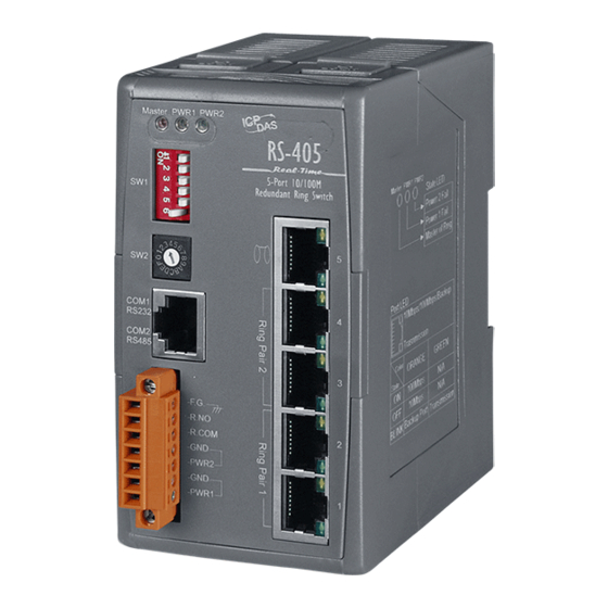
Page 8: Front Panel
Industrial Redundant Ring Switch – RS Series Quick Start Front Panel ➊ Master switch LED indicator ❷ Power 1 LED indicator ❸ Power 2 LED indicator ❹ Switch j umper block 1. Ring / Normal Switch selecting jumper 2. Reset to default jumper 3. -
Page 9: On Case Quick Guide
Industrial Redundant Ring Switch – RS Series Quick Start On Case Quick Guide The simple description of DIP and Rotate jumpers setting value, Quick Config Guide, has been printed on both right and left hand side of front panel. After acquainted with RS Series features, field engineers could deploy switches quickly by referencing Quick Config Guide. -
Page 10: Hardware Installation
Industrial Redundant Ring Switch – RS Series Quick Start Hardware Installation For hardware installation, we provide both easy DIN rail mounting DIN-Rail Mounting and wall mounting modes. Installation Wall-Mounting Installation Overview Connecting Input Power Connecting Output Relay RS Series support redundant power, output relay and enhanced Connecting Ethernet Ports ®... -
Page 11: Din-Rail Mounting Installation
Industrial Redundant Ring Switch – RS Series Quick Start DIN-Rail Mounting Installation ® With ICPDAS patent DIN-Clip design, DIN-Rail mounting installation becomes very easy. Following 3 steps completes installation. ➊ Pull the down rail clip out. Up Clip Down Clip ➋... -
Page 12: Wall-Mounting Installation
Industrial Redundant Ring Switch – RS Series Quick Start Wall-Mounting Installation ® With ICP DAS patent DIN-Clip design, Wall-Mounting installation becomes very easy. Following 2 steps completes installation. ➊ Pull out Pull out Pull all wall mounting clip out. ➋... -
Page 13: Connecting Input Power
Industrial Redundant Ring Switch – RS Series Quick Start Connecting Input Power IMPORTANT: It is good practice to turn off input and load power, and unplug the power terminal block before making wire connections. Otherwise, your screwdriver blade can inadvertently short your terminal connections to the grounded enclosure. -
Page 14: Connecting Output Relay
Industrial Redundant Ring Switch – RS Series Quick Start Connecting Output Relay The diagram of output relay: ➊ Identify R.NO and R.COM contacts on terminal block. ➋ Insert the relayed device such as a light bulb or a buzzer pair of wire, and fastening the terminal screws to prevent the wires from coming loose. -
Page 15: Connecting Ethernet Ports
Industrial Redundant Ring Switch – RS Series Quick Start Connecting Ethernet Ports RS Series includes all RJ-45 ports with automatic MDI/MDI-X crossover, and automatic 10/100Mbps data rate sensing for 10Base-T or 100Base-TX connections. Automatic MDI/MDI-X crossover allows you to connect to other switches, hubs, or workstations, without regard to using straight-through or crossover cabling. -
Page 16: Connecting Fiber Ports (Only For Models With Fiber Port)
Industrial Redundant Ring Switch – RS Series Quick Start Connecting Fiber Ports (only for models with fiber port) The automatic MDI/MDI-X crossover function does not apply to fiber connections, as these must be crossed over manually. To connect the fiber port on one switch to the fiber port of another switch, simply cross-connect the transmit channel at each end to the receive channel at the opposite end as illustrated in the figure below. -
Page 17: Configuration
Industrial Redundant Ring Switch – RS Series Quick Start Configuration This chapter provide basic techniques to form a redundant ring on your demand. One Ring Topology Two Rings Coupling Overview Two Rings Coupling with Two Phase Recovering To successfully form a robust industrial Ethernet network, the designing of network pattern is the most important stage. -
Page 18: One Ring Topology
At the moment of any connection failure, the focal point will activates the Redundant Path and fire alarm to output relay. Broken Active Path Backup Path RS Series come with 2 ring pair by default. A ring pair can form a ring with other network devices as below: TDRS0602... -
Page 19: Two Rings Coupling
Industrial Redundant Ring Switch – RS Series Quick Start Two Rings Coupling As a ring network is a small group of switches by geography, functionalities, or subsystem, 2 or more rings could be coupled together to form a whole picture of industrial network for an integrated system. -
Page 20: Two Rings Coupling With Two Phase Recovering
Industrial Redundant Ring Switch – RS Series Quick Start Two Rings Coupling with Two Phase Recovering Redundant coupling gives one more chance to keep connection alive when any connection between 2 rings has been broken. It is much safe than Single Coupling, but it takes 3 more switches to form Redundant Coupling. -
Page 21: Service Information
Industrial Redundant Ring Switch – RS Series Quick Start Service Information We sincerely hope that you never experience a problem with any ICP DAS product. If you do need service, call ICP DAS at 886-3-5973366 and ask for Applications Engineering. -
Page 22: Specifications
Industrial Redundant Ring Switch – RS Series Quick Start Appendix A Specifications Ethernet switch type Intelligent store & forward RJ45 ports (shielded) 10/100BaseT(x) RJ45 speed (auto-negotiating) 10 Mbps or 100 Mbps RJ45 auto-mdi/mdi-x All 5 ports Ethernet protocols supported All standard IEEE 802.3 Memory bandwidth 3.2 Gbps...
Need help?
Do you have a question about the RS Series and is the answer not in the manual?
Questions and answers