Table of Contents
Advertisement
Quick Links
BT5525
BATTERY INSULATION
TESTER
Read carefully before use.
Keep for future reference.
When using the instrument for the
first time
Safety Information
Part Names and Functions
Test Flow
Oct. 2022 Edition 1
BT5525A961-00 22-10H
p.12
p.18
p.24
HIOKI BT5525A961-00
Instruction Manual
Troubleshooting
Troubleshooting
Error
p.195
p.197
EN
[600630710]
Advertisement
Table of Contents

Subscribe to Our Youtube Channel
Related Manuals for Hioki BT5525


Summary of Contents for Hioki BT5525
- Page 1 BT5525 Instruction Manual BATTERY INSULATION TESTER Read carefully before use. Keep for future reference. When using the instrument for the Troubleshooting first time Safety Information p.12 Troubleshooting p.195 Part Names and Functions p.18 Error p.197 Test Flow p.24...
- Page 2 HIOKI BT5525A961-00...
-
Page 3: Table Of Contents
Limiting the Current to Be Applied Setting the test voltage in the Setting to the Device Under Test (DUT) ..64 ............35 screen ..65 Setting the current limit value manually Setting the Range (Auto/Manual) ..36 Setting the current limit value automatically ..........66 BT5525A961-00 HIOKI BT5525A961-00... - Page 4 Standard Event Status Register ....121 current source (PNP) ........85 Items restored to the default settings ..123 Connector used and signal arrangement ...85 Communications Command List ..124 ........86 Signal functions Communications Command Timing Chart ..........87 Reference ..........130 Internal Circuit Configuration ....91 HIOKI BT5525A961-00...
- Page 5 Communications settings ......167 11.6 LOW Terminal Side Test Lead 8.10 Communications Command Fabrication ...........208 Examples ..........170 Hioki LOW terminal side test lead .....208 shielded cable construction Specifications Processing the tip of the LOW terminal ..........209 side test lead 11.7 Rackmount Fittings ......211...
- Page 6 Contents HIOKI BT5525A961-00...
-
Page 7: Introduction
Introduction Introduction Thank you for choosing the Hioki BT5525 Battery Insulation Tester. To ensure your ability to get the most out of this instrument over the long term, please read this manual carefully and keep it available for future reference. -
Page 8: Checking Package Contents
Pay particular attention to included accessories, panel keys and switches, and terminals. If you find any damage or discover that the instrument does not perform as indicated in its specifications, please contact your authorized Hioki distributor or reseller. Confirm the package contents. -
Page 9: Options
Options The options listed below are available for the instrument. To order an option, please contact your authorized Hioki distributor or reseller. Options are subject to change. Check Hioki’s website for the latest information. Model name Rated voltage Rated current... -
Page 10: Symbols And Abbreviations
Indicates that the product is subject to the Waste Electrical and Electronic Equipment (WEEE) Directive in EU member nations. Dispose of the product in accordance with local regulations. Indicates that the product complies with standards imposed by EU directives. HIOKI BT5525A961-00... - Page 11 1) for a digital measuring instrument. Limit values for digit errors are expressed Digit using digits. Indicates the minimum display unit (in other words, the smallest digit that (resolution) can have a value of 1) for a digital measuring instrument. Limit values for digit errors are expressed using digits HIOKI BT5525A961-00...
-
Page 12: Safety Information
Failure to do so could cause the operator to experience an electric shock. Moreover, it could cause serious events such as heat generation, fire, and an arc flash due to a short-circuit. HIOKI BT5525A961-00... - Page 13 IV Example: Measurements on devices installed before the main fuse or circuit breaker (CAT IV) in the building installation. Distribution panel Service entrance Interior wiring Service drop CAT II CAT III CAT IV Outlet Power meter Fixed equipment HIOKI BT5525A961-00...
-
Page 14: Precautions For Use
Doing so could cause the instrument to fall or overturn, resulting in bodily injury or damage to the instrument. To prevent overheating, be sure to leave the specified clearances around the instrument. • Place with its bottom side facing downward. • Do not block vent openings. 50 mm 50 mm 50 mm HIOKI BT5525A961-00... - Page 15 Inspect the instrument and verify proper operation before use. „ Use of the instrument while it is malfunctioning could result in serious bodily injury. If you find any damage, contact your authorized Hioki distributor or reseller. Handling the instrument CAUTION Do not subject the instrument to vibration or mechanical shock while „...
- Page 16 Using the instrument to make measurements that exceed either rating could cause the operator to experience an electric shock. When using this instrument, use only Hioki specified test leads. „ Using a test lead other than the specified parts could result in bodily injury or a short- circuit.
-
Page 17: Overview
(PC) and programmable logic controller (PLC) can be connected to import the instrument controls and test results. In addition, an EXT. I/O connection is also installed and the controls of the measuring instrument, instrument status, and judgment results can be imported. HIOKI BT5525A961-00... -
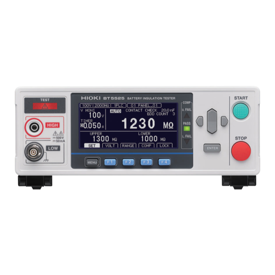
Page 18: Part Names And Functions
This instrument can be mounted on a rack. Keep any parts removed from the instrument in a safe place in case you need to use them again. See “11.7 Rackmount Fittings” (p. 2 11) , “11.8 External View” (p. 2 13) HIOKI BT5525A961-00... - Page 19 PC. RS-232C connector RS-232C communications (serial communications) p. 1 01 enables the PC to control the instrument. Measurement data can be transferred to the PC. ANALOG OUTPUT terminal Outputs measured values in analog. p. 9 7 HIOKI BT5525A961-00...
- Page 20 Be sure to unfold both of the stands. Closing the stands Fold the stands all the way. CAUTION Do not subject the instrument to excessive force from above when the stands „ are extended. Doing so could damage the stands. HIOKI BT5525A961-00...
-
Page 21: Screen Configuration And Operation Overview
Displays the test time. When the test time is set to OFF, the timer counts Timer time up. When it is set to ON, the timer counts down. Displays the voltage value between the measurement terminals being Voltage monitor value tested. HIOKI BT5525A961-00... -
Page 22: Setting Screen
Key operation sound (p. 6 7) Key lock function with a passcode (p. 6 9) Screen contrast (p. 7 2) Backlight (p. 7 3) Power supply frequency (p. 7 4) EXT. I/O test (p. 9 5) Initialization (p. 7 5) HIOKI BT5525A961-00... - Page 23 LAN MAC address Calibration date Adjustment date Adjusted by Error information (p. 1 97) The serial number consists of nine digits. The first two digits indicate the year of manufacture, while the second two digits indicate the month of manufacture. HIOKI BT5525A961-00...
-
Page 24: Test Flow
4 7 beep. Start the test. See “4.1 Starting a Test” (p. 4 9) Start measurement. End measurement. End the test. See “4.5 Ending the Test” (p. 5 5) Turn off the power after using the instrument. HIOKI BT5525A961-00... -
Page 25: Test Preparation
2 9 ▼ Connecting a communications cable to the instrument p. 3 0 ▼ Connecting the test leads to the DUT p. 3 1 ▼ Shutting down the output of the instrument (interlock function) p. 3 2 HIOKI BT5525A961-00... -
Page 26: Inspecting The Instrument Before Test
Before use, inspect the instrument and verify that it’ s operating „ properly. Using test leads or an instrument that is damaged could result in serious bodily injury. If you discover any damage, replace with a Hioki-specified part. Inspecting accessories and options Check item Action... -
Page 27: Checking The Insulation Resistance Test
(when a 100 M resistor is used). Connects the test leads to the prepared resistor. Start the test. Check that the measured resistance value matches the resistance of the prepared resistor and the comparator judgment result is [PASS]. HIOKI BT5525A961-00... -
Page 28: Supplying Power To The Instrument
Set the power frequency being used before making any measurements. Measured values will not stabilize if the power supply frequency has not been set properly. See “5.8 Manually Setting the Frequency of the Power Supply” (p. 7 4) HIOKI BT5525A961-00... -
Page 29: Turning The Instrument On And Off
When unplugging the power cord from the outlet or instrument, pull on the „ plug (not the cord). Failure to do so could cause a wire break in the power cord. The power switch is located at the back of the instrument. HIOKI BT5525A961-00... -
Page 30: Connecting The Test Leads
Failure to do so could damage the instrument or result in bodily injury. When using this instrument, use only Hioki specified test leads. „ Using a test lead other than the specified parts could result in bodily injury or a short- circuit. -
Page 31: Connecting The Test Leads To The Device Under Test (Dut)
Connect the test leads to the DUT. Black Start the test. See “4.1 Starting a Test” (p. 4 9). In order to perform a test safely, inspect the instrument prior to the test. See “2.1 Inspecting the Instrument before Test” (p. 2 6). HIOKI BT5525A961-00... -
Page 32: Shutting Down The Output Of The Instrument (Interlock Function)
When using the EXT. I/O interlock cancellation jig The included EXT. I/O interlock cancellation jig shorts the No. 3 (INTERLOCK) and No. 9 (ISO_COM) pins. The interlock state can be cancelled by connecting the jig to the instrument’s EXT. I/O connector. HIOKI BT5525A961-00... -
Page 33: Basic Settings
46 ▼ Notifying the judgment result and test completion with a beep p. 47 ▼ Checking for any contact defects and confirming contact condition p. 58 (contact check function) ▼ Detecting micro insulation failure (BDD function) p. 60 HIOKI BT5525A961-00... -
Page 34: Setting The Test Voltage
Set the test voltage to the edit mode. [VOLT] Select Change and confirm the test voltage value. • Change the value (up/down). • Change the cursor position (left/right). Select the preset voltage. [25V] [100V] [200V] [500V] Confirm [CANCEL] Cancel HIOKI BT5525A961-00... -
Page 35: Setting The Test Voltage In The Setting Screen
Setting the test voltage in the Setting screen Open the Setting screen. [SET] Select [VOLTAGE] to the edit mode. Select [EDIT] Edit Change and confirm the test voltage value. • Change the value (up/down keys) • Change the cursor position (left/right keys) Confirm [CANCEL] Cancel HIOKI BT5525A961-00... -
Page 36: Setting The Range (Auto/Manual)
Set the range to the edit mode. [RANGE] Select Change and confirm the range. Select the range [AUTO] Set the auto range [HOLD] Set the manual range [ ↓ ] Lower the range [ ↑ ] Raise the range Confirm [CANCEL] Cancel HIOKI BT5525A961-00... -
Page 37: Setting The Test Voltage In The Setting Screen
Measurement screen. See “Measurement screen” (p. 21). When analog output is used, 0 V to 4 V is output from the analog output terminal according to each resistance range. See “7.6 Using Analog Output” (p. 97). HIOKI BT5525A961-00... -
Page 38: Setting The Sampling Time
• Change the cursor position (left/right keys) Confirm [EXIT] Return to the Measurement screen IMPORTANT If the test time is shorter than the sampling time, the measured value is not displayed. Set a longer test time than the sampling time. HIOKI BT5525A961-00... -
Page 39: Setting The Measurement Delay Time
1 PLC = 1/60 = 16.7 ms Open the Setting screen. [SET] Select Set the measurement delay time. Select [EDIT] Edit • Change the value (up/down keys) • Change the cursor position (left/right keys) Confirm [EXIT] Return to the Measurement screen HIOKI BT5525A961-00... -
Page 40: Setting The Test Time And Comparator Delay Time
Check the time until the measured value is stabilized and set the test time. Open the Setting screen. [SET] Select [TIMER] to [ON]. Select (up/down keys) [ON] [OFF] Switch to the edit mode. Select (left/right keys) [EDIT] Edit HIOKI BT5525A961-00... -
Page 41: Setting The Comparator Delay Time
Comparator judgment may start before the voltage is stabilized for some DUTs. Set the comparator delay time based on the DUT. is displayed at the left side of the test time in the Measurement screen during comparator delay. HIOKI BT5525A961-00... - Page 42 Open the Setting screen. [SET] Select [COMP DELAY] to [MANUAL]. Select [MANUAL] Switch to the edit mode. Select [EDIT] Edit Set the comparator delay time. • Change the value (up/down keys) • Change the cursor position (left/right keys) Confirm [CANCEL] Cancel HIOKI BT5525A961-00...
- Page 43 Setting the Test Time and Comparator Delay Time Setting the comparator delay time to auto Open the Setting screen. [SET] Select [COMP DELAY] to [AUTO]. Select [AUTO] [EXIT] Return to the Measurement screen HIOKI BT5525A961-00...
-
Page 44: Judging The Measured Value (Comparator Function)
(underflow) due to the upper or lower limit value being less than the display range’s lower limit. • When the BDD count is 1 or greater while the comparator function and BDD judgment are enabled. See “Enabling BDD judgment” (p. 63). HIOKI BT5525A961-00... - Page 45 When the comparator function is OFF Set and confirm the value. • Change the value (up/down keys) • Change the cursor position (left/right keys) × Move the decimal point to the right × 1/10] Move the decimal point to the left Confirm HIOKI BT5525A961-00...
-
Page 46: Setting The Test Mode
FAIL STOP mode Outputs the judgment result for each sampling and ends the test when a FAIL judgment is determined. Open the Setting screen. [SET] Select Set the test mode. Select [CONT] [PASS] [FAIL] [EXIT] Return to the Measurement screen HIOKI BT5525A961-00... -
Page 47: Notifying The Judgment Result And Test Completion With A Beep
Set the conditions for the beep. Select [OFF] [PASS] [FAIL] [END] Change the tone of the beep. Press the F2, F3, or key to set the beep and check its volume. Select [TONE1] High [TONE2] Medium [TONE3] [EXIT] Return to the Measurement screen HIOKI BT5525A961-00... - Page 48 Notifying the Judgment Result and Test Completion with a Beep HIOKI BT5525A961-00...
-
Page 49: Test Method
See “2.6 Shutting Down the Output of the Instrument (Interlock Function)” (p. 32). Press the STOP key. [READY] is displayed for approximately 1 second on the Measurement screen. TEST indicator lit (during test) Press the START key while [READY] is displayed on the Measurement screen. The test starts. HIOKI BT5525A961-00... - Page 50 • Check that the test leads are properly connected before starting the test. • The test cannot be started with the EXT.I/O stop signal ON. • The test cannot be started with the interlock activated. (p. 32) HIOKI BT5525A961-00...
-
Page 51: Display During A Test
The elapsed time display is stopped when the timer counts up to 999.9 s, however, the resistance measurement is performed until the STOP key is pressed. When the comparator function is selected, a judgment is made according to the test mode setting. (p. 44) HIOKI BT5525A961-00... -
Page 52: Displaying The Measured Value
When checking the output voltage, use a high voltage test lead and check the waveform on an oscilloscope, etc. However, the linearity of the output voltage’s rising edge may be compromised due to the effects of the input impedance of the high-voltage test leads or other waveform observation probes. HIOKI BT5525A961-00... -
Page 53: Memory Function
Measurement-1 Measurement-2 Measurement-3 Measurement-4 delay measurement Measurement-1 Measurement-2 Measurement-3 Measurement-4 Saved to Saved to Saved to Saved to memory memory memory memory Time stamp N PLC+ N PLC+ N PLC+ N PLC+ M PLC M×2 PLCs M×3 PLCs M×4 PLCs HIOKI BT5525A961-00... - Page 54 200, 0,13.06E+06, PASS,2.50002E+01,1.91427E-06, 0,PASS 217, 0,12.73E+06, PASS,2.50003E+01,1.96422E-06, 0,PASS 233, 0,12.53E+06, PASS,2.50004E+01,1.99519E-06, 0,PASS 250, 0,12.67E+06, PASS,2.50003E+01,1.97332E-06, 0,PASS Time stamp (ms) Measurement status Ω Resistance value ( Judgment result Voltage value (V) Current value (A) BDD result Contact check result HIOKI BT5525A961-00...
-
Page 55: Ending The Test
This indicates that the charge remaining inside the DUT and instrument is still being discharged. Discharge any remaining electric charge according to “4.6 Discharging Residual Electric Charge (Auto Discharge Function)” (p. 56). Remove the test leads after the TEST indicator turns off. HIOKI BT5525A961-00... -
Page 56: Discharging Residual Electric Charge (Auto Discharge Function)
The electric charge remaining in the DUT is automatically discharged inside of the instrument (the TEST indicator is lit dimly). When the voltage drops below 1 V or so, the TEST indicator turns off. Remove the test leads from the DUT after the TEST indicator turns off. HIOKI BT5525A961-00... -
Page 57: Various Functions
Every Time a Test Is Completed (Auto Data Output ► value every time the test is completed. Function)” (p. 111) “8.6 Communications Command Display (Command Displays commands and response ► messages on the Measurement screen. Monitor Function)” (p. 112) HIOKI BT5525A961-00... -
Page 58: Checking For Any Contact Defects And Confirming Contact Condition (Contact Check Function)
PASS. The contact check judgment results can be checked with the setting screen, communications command, and EXT. I/O. Good contact Contact defect Timing of a contact check Perform a contact check after the test starts and before a voltage is applied. HIOKI BT5525A961-00... - Page 59 Contact check function ON [OFF] Contact check function OFF Set the judgment threshold value of the contact check. Select [EDIT] Edit • Change the value (up/down keys) • Change the cursor position (left/right keys) Confirm [EXIT] Return to the Measurement screen HIOKI BT5525A961-00...
-
Page 60: Detecting Micro Insulation Failure (Bdd Function)
BDD count occurs. Settable range: 0.6% to 999.9% IMPORTANT The BDD function’s detection precision decreases when switching ranges during auto-range operation. It is recommended to set the range manually. HIOKI BT5525A961-00... -
Page 61: Enabling The Bdd Function And Setting The Threshold Value
[SET] Select Specify the ON/OFF setting for each BDD function. Select [ON] [OFF] Set the threshold value for each BDD function. Select [EDIT] Edit • Change the value (up/down keys) • Change the cursor position (left/right keys) Confirm HIOKI BT5525A961-00... -
Page 62: Enabling The Bdd Stop Function
In addition, the EXT. I/O BDD output will turn on. • In the above example, four measured values have been saved to memory, and one BDD measured value has been saved to BDD memory, since the BDD stop function activated to end testing during the fifth measurement. HIOKI BT5525A961-00... -
Page 63: Enabling Bdd Judgment
See “3.6 Judging the Measured Value (Comparator Function)” (p. 44). Open the Setting screen. [SET] Select Enable or disable BDD judgment. Select [ON] [OFF] [EXIT] Return to the Measurement screen HIOKI BT5525A961-00... -
Page 64: Limiting The Current To Be Applied To The Device Under Test (Dut)
In addition, the contact check signal will be applied to the DUT at the start of the test. HIOKI BT5525A961-00... -
Page 65: Setting The Current Limit Value Manually
• If a capacitive load of approximately 50 μF or more is connected while the current limit value of 5.1 mA or more, constraints related to the output generator will result in an error, making measurement impossible. See “9.2 Input, Output, and Measurement Specifications” (p. 180) HIOKI BT5525A961-00... -
Page 66: Setting The Current Limit Value Automatically
[MANUAL] and adjust the current limit value to achieve the desired charging time. Factors which can cause charging to take longer than the set charging time include the instrument’s internal load and the current limit circuit’s response time. HIOKI BT5525A961-00... -
Page 67: Setting Whether To Turn On Or Off The Key Operation Sound
[COMP BEEP]. See “3.8 Notifying the Judgment Result and Test Completion with a Beep” (p. 47) A beep will be issued when an error dialog or information dialog is displayed, even if the [KEY CLICK] setting is disabled. HIOKI BT5525A961-00... -
Page 68: Enabling/Disabling The Key Operations
UNLOCK, START, and STOP are disabled. Enabling the key operations (releasing key lock) Release the key lock. [UNLOCK] Release the key lock (Press for 1 second.) [LOCK] at the upper right disappears and the key functions become enabled. HIOKI BT5525A961-00... -
Page 69: Enabling The Key Lock Function With A Passcode
Move the cursor to and press the [EDIT] key. [EDIT] Edit [EXIT] Return to the Measurement screen The passcode setting dialog box is displayed. The default setting is “” (none). HIOKI BT5525A961-00... -
Page 70: Disabling The Key Lock Function With A Passcode
Disabling the key lock function with a passcode Open the Setting screen. [SET] Select [KEY LOCK PASSCODE] to [OFF]. Select [ON] [OFF] [EXIT] Return to the Measurement screen Once the passcode is set, it is retained even when the power is turned off. HIOKI BT5525A961-00... -
Page 71: Releasing The Key Lock By Entering The Passcode
If you forget the passcode, use either of the following communications commands: • Querying and reconfiguring the passcode “Querying the key lock passcode” (p. 159) • Resetting the system “Changing the settings to the default settings (except for the communications settings)” (p. 131) HIOKI BT5525A961-00... -
Page 72: Adjusting The Screen Contrast
When the ambient temperature fluctuates, the screen may be difficult to see. Open the Setting screen. [SET] Select [LCD CONTRAST]. Select [ ↓ ] Decrease the screen contrast [ ↑ ] Increase the screen contrast [EXIT] Return to the Measurement screen HIOKI BT5525A961-00... -
Page 73: Adjusting The Backlight
“0”. If the brightness of the backlight is set to “0”, however, the display is difficult to see. Open the Setting screen. [SET] Select [LCD BACK LIGHT]. The smaller the number is, the lower the brightness becomes. Select Dark Standard Bright [EXIT] Return to the Measurement screen HIOKI BT5525A961-00... -
Page 74: Manually Setting The Frequency Of The Power Supply
Automatic recognition of the power supply frequency is performed only once when the power is turned on. When the frequency is changed from [50Hz] [60Hz] to [AUTO], turn off the power and then turn on the power again. HIOKI BT5525A961-00... -
Page 75: Initializing The Instrument (Reset)
(The interface settings are not reset.) The procedure for resetting the data in the System Setting screen is explained in this section. Open the Setting screen. [SET] Select Execute [RESET]. Select [EXEC] Execute Select [OK]. [OK] [CANCEL] Cancel HIOKI BT5525A961-00... - Page 76 Initializing the Instrument (Reset) HIOKI BT5525A961-00...
-
Page 77: Saving And Loading
Panel save function ► Items that can be saved using the panel save function See “11.9 Default Setting” (p. 214). The saved measurement conditions are loaded from the memory of the Panel load function ► instrument. HIOKI BT5525A961-00... -
Page 78: Functions)
Enter and confirm the panel name. Select Confirm [CANCEL] Cancel Key operations when the panel name is entered Operation Moves the cursor. Changes alphabetic characters and numbers. Enters 0 to 9. Enters alphabetic characters and underscores (_). Deletes characters. HIOKI BT5525A961-00... -
Page 79: Loading Measurement Conditions (Panel Load Function)
IMPORTANT The conditions can be loaded using the EXT.I/O (LOAD0 to LOAD3 and LOAD_VALID control) or *RCL communications command ( When the measurement conditions are changed after they are loaded, the panel name disap- pears from the display. HIOKI BT5525A961-00... -
Page 80: Changing The Panel Name
Change and confirm the panel name. Select Confirm [CANCEL] Cancel Key operations when the panel name is entered Operation Moves the cursor. Changes alphabetic characters and numbers. Enters 0 to 9. Enters alphabetic characters and underscores (_). Deletes characters. HIOKI BT5525A961-00... -
Page 81: Deleting Panel Data
Select the number of the panel to be deleted. The panel description is displayed at the right side of the screen. Select [CLEAR] Delete Select [OK] on the confirmation screen, or confirm using ENTER key. Confirm [OK] [CANCEL] Cancel IMPORTANT Deleted panels cannot be recovered. HIOKI BT5525A961-00... - Page 82 Deleting Panel Data HIOKI BT5525A961-00...
-
Page 83: External Control
2. Discharge static electricity from your body. 3. Check that the signal does not exceed the external input and output rating. 4. Properly isolate this instrument and the instrument to be connected to the EXT. I/O connector terminal. HIOKI BT5525A961-00... -
Page 84: Ext. I/O
Setting the EXT. I/O MODE switch (NPN/PNP) of the instrument p. 85 (After turning off the power of the instrument) ▼ Connecting the signal output destination or signal input destination to the EXT. I/O connector of the instrument ▼ Setting the instrument HIOKI BT5525A961-00... -
Page 85: External Input And Output Terminals And Signals
The connector frame is connected to a metal part on the back of the instrument and protective ground terminal of the power inlet. Connector used D-sub 37-pin female #4-40 inch screw Compatible DC-37P-ULR (soldered type) connector DCSP-JB37PR (pressure welded type) Japan Aviation Electronics Industry, Ltd. See “Interface specifications” “(4) EXT. I/O” (p. 187). HIOKI BT5525A961-00... -
Page 86: Signal Functions
• When a fan error occurs • When a model information error occurs • When a setting backup error occurs EXT. I/O input and output signals cannot be used while the measurement conditions are being changed inside the instrument. HIOKI BT5525A961-00... -
Page 87: Timing Chart
In the following cases, up to 1 s is added to the START signal detection time. • The START signal is input after the test voltage is changed. • The test voltage is changed using the LOAD signal or communications command. HIOKI BT5525A961-00... - Page 88 Based on the setting × Measurement time 50 Hz: 20 ms PLC setting × 60 Hz: 16.7 ms PLC setting Calculation time 1 ms max. Discharge time 20 ms max. (at pure resistance measurement) START setup time 40 ms HIOKI BT5525A961-00...
- Page 89 50 Hz: 20 ms PLC setting × 60 Hz: 16.7 ms PLC setting Calculation time 1 ms max. Discharge time 20 ms max. (at pure resistance measurement) Contact check time 50 Hz: 50 ms, 60 Hz: 46.7 ms HIOKI BT5525A961-00...
- Page 90 LOAD0 Specify the panel number. (Input) LOAD1 Specify the panel number. (Input) LOAD2 Specify the panel number. (Input) LOAD3 Specify the panel number. (Input) Execute panel load LOAD_VALID (Input) Description Time LOAD_VALID signal detection time 3 ms min. HIOKI BT5525A961-00...
-
Page 91: Internal Circuit Configuration
Internal Circuit Configuration 7.3 Internal Circuit Configuration NPN setting Do not connect an external power supply to pin 8. BT5525 PLC, etc. ISO_5 V Ω Ω START Output STOP Common EXT. I/O Internal isolated MODE power supply PLC, etc. selector Ω... -
Page 92: Pnp Setting
Internal Circuit Configuration PNP setting Do not connect an external power supply to pin 8. BT5525 PLC, etc. ISO_5 V Ω Ω Output START STOP Common EXT. I/O Internal isolated MODE PLC, etc. power supply selector Ω Input SYSTEM_ERR Zener voltage 30 V... -
Page 93: Electrical Specifications
Internal Circuit Configuration Electrical specifications See “EXT. I/O” (p. 187) Connection examples Input circuit connection example BT5525 BT5525 Input Input ISO_COM ISO_COM Connection with a switch Connection with a relay BT5525 BT5525 Input Output Input Output ISO_COM Common ISO_COM Common... - Page 94 Internal Circuit Configuration Output circuit connection example BT5525 BT5525 Output Output 50 mA max. 50 mA max. ISO_COM ISO_COM 30 V max. Connection with a relay Connection with an LED BT5525 BT5525 Output Output 50 mA max. Active low Output...
-
Page 95: Checking External Control
• The TEST and VON signals cannot be manipulated using the EXT. I/O test function. To check signals, start an actual insulation resistance test. • The LOAD0 to LOAD3 signals are finalized and displayed when the LOAD_VALID signal is input. HIOKI BT5525A961-00... -
Page 96: Accessory Connector Assembly Procedure
Using any other type of cables can cause the system to malfunction due to noise. • Connect the shield to the ISO_COM terminal of the EXT. I/O connector. • If you lose or damage the provided screws, contact your authorized Hioki distributor or reseller. Tools to be prepared... -
Page 97: Using Analog Output
(100 V ≤ V ≤ 500 V) Over.F Total resistance range Under.F IMPORTANT When the resistance falls below the resistance display range, [Under. F] is displayed on the screen and 0 V is output from the analog output terminal. See “Resistance measurement” (p. 180). HIOKI BT5525A961-00... -
Page 98: Connecting An Output Cord
Do not connect the output cord plug to the measurement terminal of the „ instrument. Doing so may damage the instrument and output cord. Connect the output cord plug to the analog output terminal on the back of the instrument. HIOKI BT5525A961-00... -
Page 99: Communications Function
PC, the instrument and PC may be damaged or malfunction. Once the communications cable is connected, tighten the screws on the „ connector. Otherwise, data may not be transferred properly. HIOKI BT5525A961-00... -
Page 100: Interface Overview And Features
Measurement screen. Any operation keys except for the key and key become disabled. [LOCAL] Cancels the remote state and returns to the local state. Stops measurement. Pressing the MENU key cancels the remote state and enables the key operations. HIOKI BT5525A961-00... -
Page 101: Rs-232C Interface
• Start/stop synchronization • Communications speed: 9600 bps / 19200 bps / 38400 bps / 57600 bps (According to the instrument setting) • Stop bit: 1 • Data length: 8 • Parity check: None • Flow control: None HIOKI BT5525A961-00... -
Page 102: Connecting The Rs-232C Cable
Not used Ring indicator Not used When connecting the instrument and a computer Use a cross cable with D-sub 9-pin female and D-sub 9-pin female. Recommended cable: Hioki L9637 RS-232C Cable (3 m) See “L9637 RS-232C Cable” (p. 192). HIOKI BT5525A961-00... -
Page 103: Lan Interface
Create a program and connect to the communications command port with the TCP to control the instrument using communications commands. Preparation procedure Setting the communications conditions of the instrument p. 106 ▼ Connecting a LAN cable p. 109 HIOKI BT5525A961-00... -
Page 104: Settings For The Communications Conditions
Setting example IP address Set the serial numbers as follows. Computer: 192.168.0.1 Instrument first unit: 192.168.0.2 Instrument second unit: 192.168.0.3 Instrument third unit: 192.168.0.4 ↓ Subnet mask: 255.255.255.0 Gateway: Communications command port number: HIOKI BT5525A961-00... - Page 105 IP address in the computer settings. One instrument and one computer connection, gateway not used Set the default gateway IP address to 0.0.0.0. Communications Sets the TCP/IP port number to be used for connection. command port number HIOKI BT5525A961-00...
-
Page 106: Setting The Communications Conditions
Open the Setting screen. [SET] Select [LAN IP ADDRESS] to the edit mode. Select [EDIT] Edit Set the IP address. Select Confirm [CANCEL] Cancel [SUBNET MASK] to the edit mode. Select [EDIT] Edit Set the subnet mask. Select Confirm [CANCEL] Cancel HIOKI BT5525A961-00... - Page 107 LAN Interface [DEFAULT GATEWAY] to the edit mode. Select [EDIT] Edit Set the default gateway. Select Confirm [CANCEL] Cancel [TCP PORT] to the edit mode. Select [EDIT] Edit Set the communications command port. Select Confirm [CANCEL] Cancel HIOKI BT5525A961-00...
-
Page 108: Setting The Lan Communications
Set the NoDelay property of the TcpClient class to “true”. ® ® ® For Visual C /C++ Microsoft Foundation Class, Visual Basic for Applications Set TCP_NODELAY of the socket option to 1. When using other programming languages, refer to the applicable document. HIOKI BT5525A961-00... -
Page 109: Connecting A Lan Cable
Orange LED Lit: Linking Off: 10BASE-T Blinking: Communicating Lit: 100BASE-TX If the green indicator does not light up even when the LAN is connected, the instrument or connected instruments may be damaged or the LAN cable may be broken. HIOKI BT5525A961-00... -
Page 110: Usb Interface
Connecting the USB cable Connect a USB cable type AB (commercially available) to the USB connector of the instrument. CAUTION Do not unplug the USB cable while communications are ongoing. „ Doing so could damage the instrument or computer. Type B HIOKI BT5525A961-00... -
Page 111: Automatically Sending The Measured Value Every Time A Test Is Completed (Auto Data Output Function)
[LAN] Select the data type. Select [TYPE1] Sends automatically in the format of type 1 [TYPE2] Sends automatically in the format of type 2 [EXIT] Return to the Measurement screen :SYSTem:COMMunicate:DATAout See “Communications settings” (p. 167) “ command”. HIOKI BT5525A961-00... -
Page 112: Communications Command Display (Command Monitor Function)
Open the Setting screen. [SET] Select [CMD MONITOR] to [ON]. Select [ON] [OFF] [EXIT] Return to the Measurement screen The communications command that has been sent and received is displayed on the Measurement screen. HIOKI BT5525A961-00... - Page 113 #RS: Parity Error When a parity error occurs #RS: Framing Error When a framing error occurs When these characters are displayed, check the communications conditions or lower the communications speed. The error position may shift when commands are consecutively received. HIOKI BT5525A961-00...
-
Page 114: Communications Method
A query message is used to query operation results, measurement results, and settings of the instrument. Example: Command to query the current test voltage :VOLTage? Header Question mark See “Header” (p. 1 15), “Separator” (p. 1 16), and “Data” (p. 1 17). HIOKI BT5525A961-00... - Page 115 This header is used to query the settings of the instrument and measured values. As shown in the following examples, it is recognized as a query when a question mark ( ) is added after a program header. *STB? Example: :SYSTem:ERRor? HIOKI BT5525A961-00...
- Page 116 In a message consisting of a header and data, the header is separated from the data using a space (blank). :VOLTage 100 Example: Space (3) Data separator In a message containing multiple data items, a comma ( ) is required to separate the data items from one another. :SYSTem:COMMunicate:LAN:IPADdress 192,168,1,1 Example: Comma HIOKI BT5525A961-00...
- Page 117 The format consisting of all three types above is called the “NRf format”. The instrument recognizes numeric data in the NRf format. The response data is sent in the format specified for each command. :VOLTage 100 Example: :TIMer 1.5 HIOKI BT5525A961-00...
- Page 118 ) is not required at the start of the simple and compound command type headers. However, to avoid confusion with abbreviated forms and malfunction of the instrument, we recommend placing a colon ( ) at the start of a command. HIOKI BT5525A961-00...
-
Page 119: Output Queue And Input Buffer
(To clear the bits, the query for each event register should be executed to *CLS clear each cause or should be executed.) *SRE Masks bits reporting the status of the Status Byte Register to the Status *SRE? Byte Register’s MSS bit (bit 6). See “Status Byte Register (STB)” (p. 120) HIOKI BT5525A961-00... - Page 120 Bit 2 Bit 1 Bit 0 Status Byte Register – – – – (STB) Service Request Enable – – – – Register (SRER) Bit 7 Bit 6 Bit 5 Bit 4 Bit 3 Bit 2 Bit 1 Bit 0 HIOKI BT5525A961-00...
-
Page 121: Standard Event Status Register
(Control Request) Operation Complete This bit is set to “1” when the operation is completed. *OPC Bit 0 • When the command is executed *OPC • When the operation of all messages up to the command is completed HIOKI BT5525A961-00... - Page 122 Standard Event Status Enable Register (SESER) Queries and settings for registers Register Query Settings *STB? Status Byte Register – *SRE? *SRE Service Request Enable Register *ESR? Standard Event Status Register – *ESE? *ESE Standard Event Status Enable Register HIOKI BT5525A961-00...
-
Page 123: Items Restored To The Default Settings
Status Byte Register – * Event Register * – Enable Register – – Current path – – *1: Clears bits other than the MAV bit. *2: Excludes the PON bit (bit 7). HIOKI BT5525A961-00... -
Page 124: Communications Command List
Querying the voltage monitor value p. 139 :MEASure:CLEar Clearing the measured value p. 139 :MEASure:COUNt? Querying the number of measured p. 139 values saved in the memory :MEASure:MEMory? [CRLF] Querying the measured values saved in p. 139 the memory HIOKI BT5525A961-00... - Page 125 145 :CONTactcheck:CAPacitance:THReshold? Querying the judgment threshold value of the contact check :CONTactcheck:EXECute Excecuting the contact check p. 145 :CONTactcheck:CAPacitance? Querying the contact check capacitance p. 146 value :CONTactcheck:RESult? Querying the contact check judgment p. 146 result HIOKI BT5525A961-00...
- Page 126 Querying the BDD measured values p. 150 saved in the memory :BDD:STOP {ON|OFF} Setting the BDD stop function p. 150 :BDD:STOP? Querying the BDD stop function TIMer <Test time> Test time Setting test time (timer) p. 151 :TIMer? Querying test time (timer) HIOKI BT5525A961-00...
- Page 127 Loading measurement conditions (panel p. 155 [:SYSTem]:PANel:LOAD <Panel number> loading) [:SYSTem]:PANel:CLEar <Panel number> Deleting the saved measurement p. 155 conditions (panel deletion) [:SYSTem]:PANel:NAME <Panel Setting the panel name number>,<"Panel name"> p. 155 [:SYSTem]:PANel:NAME? <Panel number> Querying the panel name HIOKI BT5525A961-00...
- Page 128 Querying the calibration date p. 160 :SYSTem:RESet Changing the settings to the default settings (except for the communications p. 160 settings) :SYSTem:COMMunicate:RS232C:SPEed RS-232C Setting the RS-232C communications <Communications speed> speed p. 161 :SYSTem:COMMunicate:RS232C:SPEed? Querying the RS-232C communications speed HIOKI BT5525A961-00...
- Page 129 Setting the command monitor function p. 169 :SYSTem:COMMunicate:MONitor? Querying the command monitor function p. 169 :SYSTem:LOCal Returning to the local state p. 169 Command lower case letters can be omitted. Commands with both upper case and lower case letters are accepted. HIOKI BT5525A961-00...
-
Page 130: Communications Command Reference
Indicates the syntax of communications commands. The command data or response message is described. Describes the command. Indicates an example of using the actual command. ␣ The blank (0x20) in the query example is indicated as “ ”. Command, query Response HIOKI BT5525A961-00... -
Page 131: Standard Command
Executes a self-test for the instrument and returns the result. PASS is returned when the instrument passes the test. FAIL Repair is necessary if is returned. Please contact your authorized Hioki distributor or reseller. *TST? Example PASS A self-test has been executed and it has found no problem. -
Page 132: Waiting For The Current Operation To Complete And Setting The Operation Completion Bit Of The Standard Event Status Register (Sesr) To
The subsequent command is not executed until the current operation is completed. *OPC Unlike , “1” is not set to the OPC bit of the Standard Event Status Register (SESR). *OPC Otherwise, everything else is the same as HIOKI BT5525A961-00... -
Page 133: Event Register
Queries the Standard Event Status Register (SESR) value. Bit 7 Bit 6 Bit 5 Bit 4 Bit 3 Bit 2 Bit 1 Bit 0 *OPC Example *ESR? *OPC “1” is set for the OPC bit of the Standard Event Status Register (SESR) with HIOKI BT5525A961-00... -
Page 134: Querying The Service Request Enable Register (Srer)
Queries the Status Byte Register (STB) value. Bit 7 Bit 6 Bit 5 Bit 4 Bit 3 Bit 2 Bit 1 Bit 0 – – – – *STB? Example “1” has been set for the ERR bit of the Status Byte Register (STB). HIOKI BT5525A961-00... -
Page 135: Error
For instance, an execution error occurs while a test is being performed, an interlock is activated, the EXT. I/O STOP signal is ON, etc. :STARt Example Starts the test. Ending the test :STOP Syntax Command Description Ends the test. :STOP Example Ends the test. HIOKI BT5525A961-00... -
Page 136: Measurement Command
Bit 3 Bit 2 Bit 1 Bit 0 Current value Voltage value Resistance Measurement Contact check BDD result Result Time stamp result Ω value ( status :MEASure:VALid? Example ␣ The time stamp, resistance value, and judgment result are returned. HIOKI BT5525A961-00... -
Page 137: Measured Value Output
• If the set upper and lower limit values are less than the display range’s lower limit value, and the measured value is [Under.F] (underflow) • When the BDD count is at least 1 while the comparator function and BDD judgment are enabled HIOKI BT5525A961-00... - Page 138 200 M X X X . X E + 0 6 Ω 2000 M X X X X E + 0 6 X X X X X E + 0 6 Auto Numerical format for the confirmed range HIOKI BT5525A961-00...
-
Page 139: Querying The Voltage Monitor Value
An execution error occurs if the measured values are not saved in the memory. :MEASure:MEMory? Example 120.0E+06,123.4E+06,124.5E+06,130.9E+06,150.0E+06 Five measured values are saved in the memory and the respective resistance values are Ω Ω Ω Ω Ω 120.0 M , 123.4 M , 124.5 M , 130.9 M , and 150.0 M HIOKI BT5525A961-00... -
Page 140: Measurement Settings
Querying the resistance range :RANGe? Syntax Query <Resistance range> Response (2 to 5 bytes + • Resistance range {2M|20M|200M|2000M} CRLF) Returns the resistance range. Description Queries the resistance range. :RANGe? Example Ω The resistance range setting is 20 M HIOKI BT5525A961-00... - Page 141 Querying the sampling time (measurement speed) :SPEed? Syntax Query <Sampling time> Response (3 bytes + • Sampling time {1 to 100} CRLF) Returns the sampling time. Description Queries the sampling time. :SPEed? Example ␣␣ The sampling time setting is 5 PLCs. HIOKI BT5525A961-00...
- Page 142 Response <Current limit value> (9 bytes + • Current limit value {0.05E-03 to 50.00E-03} CRLF) Returns the current limit value. Description Queries the current limit value. :CHARge:LIMit? Example ␣ 5.00E-03 The current limit value setting is 5 mA. HIOKI BT5525A961-00...
- Page 143 Querying the charging time :CHARge:TIME? Syntax Query <Charging time> Response (6 bytes + • Charging time {0.001 to 10.000} CRLF) Returns the charging time. Description Queries the charging time. :CHARge:TIME? Example ␣ 1.000 The charging time setting is 1 second. HIOKI BT5525A961-00...
- Page 144 Querying the auto capacitance value of the DUT :CHARge:CAPacity:AUTO? Syntax Query {ON|OFF} Response (2 or 3 bytes + CRLF) Description Queries the auto capacitance value of the DUT. :CHARge:CAPacity:AUTO? Example The auto capacitance value of the DUT is ON (AUTO). HIOKI BT5525A961-00...
-
Page 145: Contact Check
ON will result in an execution error. It may take up to 50 ms from execution until completion. Query the contact check capacitance value and judgment result after the contact check completes. :CONTactcheck:EXECute Example Performs a contact check. HIOKI BT5525A961-00... -
Page 146: Bdd
Querying the BDD judgment using the CC (charging) voltage :BDD:CC:V? Syntax Query {ON|OFF} Response (2 or 3 bytes + CRLF) Description Queries the BDD judgment setting using the CC (charging) voltage. :BDD:CC:V? Example The BDD judgment using the CC (charging) voltage is set. HIOKI BT5525A961-00... - Page 147 :BDD:CV:V? Syntax Query {ON|OFF} Response (2 or 3 bytes + CRLF) Description Queries the BDD judgment setting using the CV (steady state) voltage. :BDD:CV:V? Example The BDD judgment is to be performed using the CV (steady state) voltage. HIOKI BT5525A961-00...
- Page 148 Querying the BDD judgment using the CV (steady state) current :BDD:CV:I? Syntax Query {ON|OFF} Response (2 or 3 bytes + CRLF) Description Queries the BDD judgment using the CV (steady state) current. :BDD:CV:I? Example The BDD judgment is to be performed using the CV (steady state) current. HIOKI BT5525A961-00...
- Page 149 BDD measured values after that are not saved. By querying the number of measured values saved in the memory, you can find out the :BDD:MEMory? number of measured values returned with the query. :BDD:COUNt? Example Twenty three BDD measured values are saved in the memory. HIOKI BT5525A961-00...
- Page 150 {ON|OFF} Response (2 or 3 bytes + CRLF) Description Queries whether to stop the test when the BDD count is 1 or more. :BDD:STOP? Example The test is to stop when the BDD count is 1 or more. HIOKI BT5525A961-00...
-
Page 151: Test Time
• Comparator delay time {0.000|0.001 to 999.999} CRLF) Returns the comparator delay time. Description Queries the comparator delay time. 0.000 is returned when the comparator delay time is auto (AUTO). :COMParator:DELay? Example ␣ 10.000 The comparator delay time setting is 10 seconds. HIOKI BT5525A961-00... - Page 152 <Test mode> Response (8 bytes + • Test mode {CONTINUE|PASSSTOP|FAILSTOP} CRLF) Returns the comparator test mode. Description Queries the comparator test mode. :COMParator:MODE? Example PASSSTOP The test is to be ended when the comparator judgment result is PASS. HIOKI BT5525A961-00...
- Page 153 Syntax Query <Beep> Response (3 or 4 bytes + • Beep {OFF|PASS|FAIL|END} CRLF) Return the comparator beep. Description Queries the comparator beep. :COMParator:BEEPer? Example PASS A beep is to be issued when the comparator judgment result is PASS. HIOKI BT5525A961-00...
-
Page 154: Saving And Loading The Measurement Conditions
(1 byte + CRLF) Description Queries whether the measurement conditions are saved to the specified panel number. The measurement conditions are not saved. The measurement conditions are saved. *SAV? 3 Example The measurement conditions are saved to panel number 3. HIOKI BT5525A961-00... - Page 155 Specifies the panel name. Description Sets the panel name. The panel name is enclosed in double quotation marks ("). :SYSTem:PANel:NAME 3,"HIOKI" Example The panel name for panel No. 3 is set to “HIOKI”. Querying the panel name :PANel:NAME? <Panel number> [:SYSTem] Syntax Query •...
-
Page 156: System Settings
(3 bytes + • A multiple of 5 within the contrast setting range of {0 to 100} CRLF) Returns the LCD contrast setting. Description Queries the LCD contrast setting. :DISPlay:CONTrast? Example ␣ The LCD contrast setting is 60. HIOKI BT5525A961-00... - Page 157 <Power supply frequency> Response (2 or 4 bytes + • Power supply frequency {AUTO|50|60} CRLF) Returns the power supply frequency setting. Description Queries the power supply frequency setting. :SYSTem:LFRequency? Example The power supply frequency setting is 60 Hz. HIOKI BT5525A961-00...
- Page 158 Sets the key lock state. :SYSTem:KLOCk ON Example The key is set to be locked. Querying the key lock state :SYSTem:KLOCk? Syntax Query {ON|OFF} Response (2 or 3 bytes + CRLF) Description Queries the key lock state. :SYSTem:KLOCk? Example Key lock HIOKI BT5525A961-00...
- Page 159 The passcode is enclosed in double quotation marks ("). The passcode is not changed if it is optional. :SYSTem:KLOCk:PASScode ON,"HIOKI" Example The key lock passcode setting is enabled and the passcode is set to “HIOKI”. Querying the key lock passcode :SYSTem:KLOCk:PASScode? Syntax Query {ON|OFF},<"Passcode">...
- Page 160 Changing the settings to the default settings (except for the communications settings) :SYSTem:RESet Syntax Command Description Sets the instrument to the default settings. The communications settings, however, are not changed. See “11.9 Default Setting” (p. 214) :SYSTem:RESet Example Performs a system reset. HIOKI BT5525A961-00...
- Page 161 :SYSTem:COMMunicate:RS232C:SPEed? Syntax Query <Communications speed> Response (4 to 5 bytes + • Communications speed {9600|19200|38400|57600} CRLF) Returns the communications speed setting. Description Queries the RS-232C communications speed. :SYSTem:COMMunicate:RS232C:SPEed? Example 19200 The RS-232C communications speed setting is 19200 bps. HIOKI BT5525A961-00...
-
Page 162: Lan
The currently set IP address is returned if the command for setting the IP address is not sent. :SYSTem:COMMunicate:LAN:IPADdress:PREParation? Example 192,168,1,100 The LAN IP address to be enabled after confirmation of the LAN settings is 192.168.1.100. HIOKI BT5525A961-00... - Page 163 LAN:UPDate command is sent. The currently set subnet is returned if the command for setting the subnet mask is not sent. :SYSTem:COMMunicate:LAN:SMASk:PREParation? Example 255,255,255,0 The subnet mask to be enabled after confirmation of the LAN settings is 255.255.255.0. HIOKI BT5525A961-00...
- Page 164 The currently set default gateway is returned if the command for setting the default gateway is not sent. :SYSTem:COMMunicate:LAN:GATeway:PREParation? Example 192,168,0,200 The default gateway to be enabled after confirmation of the LAN settings is 192.168.0.200. HIOKI BT5525A961-00...
- Page 165 It is used to confirm the port number set before the command is sent. The currently set port number is returned if the command for setting the port number is not sent. :SYSTem:COMMunicate:LAN:CONTrol:PREParation? Example The port number to be set after confirmation of the LAN settings is 23. HIOKI BT5525A961-00...
- Page 166 <MAC address> Response (19 bytes + • MAC address CRLF) Returns the MAC address using a character string such as “00-01-67- 00-00-00”. Description Queries the MAC address of the instrument. :SYSTem:COMMunicate:LAN:MAC? Example "00-01-67-00-00-00" The MAC address is 00-01-67-00-00-00. HIOKI BT5525A961-00...
-
Page 167: Communications Settings
X X X X Auto X X X X X Numerical format for the confirmed range TYPE2 :MEASure? :MEASure:VALid? Data is output in the format same as according to the setting. :MEASure? See the query for the format. HIOKI BT5525A961-00... - Page 168 Returns the data output format. Description Queries the interface to which data is automatically output and the data format. :SYSTem:COMMunicate:DATAout? Example RS232C,TYPE1 The interface to which data is automatically output is RS-232C and the data format is TYPE1. HIOKI BT5525A961-00...
- Page 169 The command monitor function is to be used. Returning to the local state :SYSTem:LOCal Syntax Command Description Cancels the remote state via communications and returns to the local state. The key operation is enabled. :SYSTem:LOCal Example The remote state is canceled. HIOKI BT5525A961-00...
-
Page 170: Communications Command Examples
The terminator (CR+LF) added to responses is also omitted in the same manner. Verification example before measurement This is an example of checking the instrument status, acquiring the instrument information, etc. before measurement. Sent to the BT5525 from Example of the BT5525 Description the controller response *IDN? HIOKI,BT5525,220612345,V1.00... - Page 171 Communications Command Examples Basic measurement example The following is an example of setting the measurement conditions and acquiring the measurement result of a 3-second test. Sent to the BT5525 from Example of the BT5525 Description the controller response :VOLTage 150 Set the test voltage to 150 V.
- Page 172 Communications Command Examples Example of acquiring the time stamp, measurement status, and measured value The following is an example of acquiring the time stamp, measurement status, and measured value. Sent to the BT5525 from Example of the BT5525 Description the controller...
- Page 173 Communications Command Examples Example of using a contact check The following is an example setting and enabling the threshold value of the contact check. Sent to the BT5525 from Example of the BT5525 Description the controller response :CONTactcheck:CAPacitance: Set the judgment threshold –...
- Page 174 Measurement example using the comparator This is an example that a judgment is made in 5 seconds after a test starts, a beep sounds when the judgment is PASS, and then the test ends. Sent to the BT5525 from Example of the BT5525 Description...
- Page 175 Communications Command Examples Measurement example using the BDD function This is an example of setting and using the BDD function. Sent to the BT5525 from Description Example of the BT5525 response the controller :BDD:CC:V ON Enable the BDD judgment –...
- Page 176 Communications Command Examples Example of saving and loading the measurement conditions (panel saving and panel loading) This is an example of saving multiple measurement conditions at once. Sent to the BT5525 from the Description Example of the BT5525 response controller :VOLTage 500 Set the test voltage to 500V.
- Page 177 Communications Command Examples Examples of LAN communications settings The following are examples of setting the IP address, port number, etc. Sent to the BT5525 from Example of the Description the controller BT5525 response :SYSTem:COMMunicate:LAN:IPADdress Setting the IP address – 172,16,1,100...
- Page 178 Communications Command Examples Example of checking that commands are properly processed This is an example of checking that commands sent from the controller to the instrument are properly processed. Sent to the BT5525 from Example of the BT5525 Description the controller...
-
Page 179: Specifications
(Standard equipment) RS-232C × × × × Dimensions Approx. 215W 306.5D mm (8.46″W 3.15″H 12.07″D) (excluding protruding parts) Weight Approx. 2.8 kg (98.8 oz.) Product warranty 3 years duration Included accessories See p. 8 Options See p. 9 HIOKI BT5525A961-00... -
Page 180: Input, Output, And Measurement Specifications
AUTO or 0.001 s to 999.999 s delay time Set resolution 1 ms Operation Comparator judgment is not performed until the response time has elapsed after the start of measurement. The timer counts up along with the test time. HIOKI BT5525A961-00... -
Page 181: Accuracy Specifications
Accuracy guarantee range 0.050 s (50 ms) to 999.999 s ± Test time accuracy 0.005 s (0.050 s to 0.099 s of set range) ± 0.05 s (0.100 s to 9.999 s of set range) ± 0.5 s (10.000 s to 999.999 s of set range) HIOKI BT5525A961-00... -
Page 182: Functional Specifications
FAIL judgment is given. Judgment value range Charging (CC V) 0.1 V to 500.0 V Steady state (CV V) 0.1 V to 500.0 V Steady state (CV I) 0.6% to 999.9% See “5.2 Detecting Micro Insulation Failure (BDD Function)” (p. 60). HIOKI BT5525A961-00... - Page 183 (7) Sampling time Setting range 1 PLC to 100 PLCs See “3.3 Setting the Sampling Time” (p. 38). (8) Measurement delay time Setting range 1 PLC to 100 PLCs See “3.4 Setting the Measurement Delay Time” (p. 39). HIOKI BT5525A961-00...
- Page 184 1 second. See “5.5 Enabling/Disabling the Key Operations” (p. 68) (14) Automatic discharge function Operations The DUT is discharged at 40 mA or more after measurement is completed. See “4.6 Discharging Residual Electric Charge (Auto Discharge Function)” (p. 56) HIOKI BT5525A961-00...
- Page 185 The measured value (exponent display 000.0E + 06) is displayed. Interface: The operations are based on the interface settings. See “8.5 Automatically Sending the Measured Value Every Time a Test Is Completed (Auto Data Output Function)” (p. 111) HIOKI BT5525A961-00...
-
Page 186: Interface Specifications
IP address, subnet mask, default gateway Communications command port number (1 to 65535) Default setting IP address 192.168.1.1 Subnet mask 255.255.0.0 Default gateway 0.0.0.0 (None) Communications command port Delimiter When sending CR+LF When receiving CR, LF, CR+LF See “8.3 LAN Interface” (p. 103) HIOKI BT5525A961-00... - Page 187 Source output: −5.0 V Maximum output current 100 mA Isolation Protective ground potential and isolated measurement circuit Line-to-earth voltage 50 V DC, 30 V rms AC, 42.4 V peak AC or less See “7 External Control (EXT. I/O)” (p. 83) HIOKI BT5525A961-00...
- Page 188 – – – – – – – – – – – – – – – – – – The input signals to the instrument are indicated as IN and the output signals as OUT in the table above. HIOKI BT5525A961-00...
-
Page 189: Other Specifications
Adjustment range 0 to 100 (Resolution: 5) Backlight Setting range 0: OFF (0 can be set only using a communications command.) 1: Dark 2: Standard 3: Bright Lifetime 100000 hours Indicator Display TEST PASS U. FAIL L. FAIL HIOKI BT5525A961-00... -
Page 190: Specifications Of The Options
None (not eligible) duration Rated current 50 mA Ω Insulation resistance 10 G (between the main electrode and internal shield at 500 V DC) Rated voltage between 500 V (anticipated transient overvoltage: 50 V) input terminal and ground HIOKI BT5525A961-00... -
Page 191: L2132 Unterminated Lead
None (not eligible) duration Rated current 50 mA Ω Insulation resistance 10 G (between the main electrode and internal shield at 500 V DC) Rated voltage between 500 V (anticipated transient overvoltage: 50 V) input terminal and ground HIOKI BT5525A961-00... -
Page 192: L9094 Output Cord
F), 80% RH or less (non-condensing) and humidity range Length Approx. 3000 mm (118.11″) (including connector) Weight Approx. 215.4 g (7.6 oz.) Product warranty None (not eligible) duration Connector D-sub 9-pin female to D-sub 9-pin female Cable Cross cable S: Shield HIOKI BT5525A961-00... -
Page 193: Maintenance And Service
The calibration period varies with the conditions and environment of use. It is recommended to determine a calibration period based on those factors and to have the instrument regularly calibrated by Hioki. Please contact your Hioki distributor to have your instrument periodically calibrated. -
Page 194: Replaceable Parts And Service Lives
It is recommended to replace these parts regularly to ensure instrument functionality over the long term. To order replacements, please contact your Hioki distributor. Part service life varies with the operating environment and frequency of use. These parts are not guaranteed to operate throughout the period defined by the recommended replacement interval. -
Page 195: Troubleshooting
10.2 Troubleshooting If damage is suspected, read the “Before requesting repair” section to remedy the problem. If this does not help you, contact your authorized Hioki distributor or reseller. When an error is displayed on the LCD screen, repair is necessary. - Page 196 A contact check • The test lead is broken. • Check the continuity of the test lead – error occurs. using a tester. • The test leads are not in contact • Check the wiring. – with the DUT. HIOKI BT5525A961-00...
-
Page 197: Error
Error 10.3 Error HIOKI BT5525A961-00... - Page 198 Error HIOKI BT5525A961-00...
-
Page 199: License Information
SERVICES; LOSS OF USE, DATA, OR PROFITS; OR BUSINESS INTERRUPTION) HOWEVER CAUSED AND ON ANY THEORY OF LIABILITY, WHETHER IN CONTRACT, STRICT LIABILITY, OR TORT (INCLUDING NEGLIGENCE OR OTHERWISE) ARISING IN ANY WAY OUT OF THE USE OF THIS SOFTWARE, EVEN IF ADVISED OF THE POSSIBILITY OF SUCH DAMAGE HIOKI BT5525A961-00... - Page 200 License Information HIOKI BT5525A961-00...
-
Page 201: Appendix
A switching power supply with a wide input range between 100 V and 240 V is used for the power supply unit and stable measurement can be performed even in a poor power environment. HIOKI BT5525A961-00... -
Page 202: Current Limit And Relationship Between Measured Resistance And Output Voltage
200 µA and test voltage to 500 V, the output voltage is calculated as follows. Due to this, the output voltage goes up only to approximately 200 V. × Ω 200 µA = 200 V HIOKI BT5525A961-00... -
Page 203: Influence Of Capacitive Load
• If a capacitive load of approximately 50 μF or more is connected while using a current limit value of 5.1 mA or more, constraints related to the output generator will result in an error, making measurement impossible. See “9.2 Input, Output, and Measurement Specifications” (p. 180) HIOKI BT5525A961-00... - Page 204 HIGH side L2133 Unterminated Lead (black) Instrument settings Test voltage 100 V Ω Resistance range 2000 M range Ω Load 1000 M Cable length Measurement speed ± ± ± ± ± 1 PLC 0.2% 0.1% 0.3% 0.3% 0.3% HIOKI BT5525A961-00...
-
Page 205: Influence Of Noise
Since stray capacitance is inversely proportional to distance, a clearance from the noise source is required. Ensure sufficient distance in the same manner between signal lines of different types, power supply and signal lines, input and output lines, and grounding and signal lines as well. HIOKI BT5525A961-00... - Page 206 RS-232C Isolation EXT. I/O Instrument Controller (PC, PLC) Common mode filter to the transmission path Power supply line Isolation Separate the power Power supply line of other systems supply line. Welding Inverter Motor machine Conductive noise countermeasure HIOKI BT5525A961-00...
-
Page 207: Change In The Current Flowing Through Insulators
Depending on the magnitude of voltage “C ” in Fig. 1, generally a discharge time that is 5 to 6 times the time for which a voltage is applied during measurement is required. HIOKI BT5525A961-00... -
Page 208: Low Terminal Side Test Lead Fabrication
LOW Terminal Side Test Lead Fabrication 11.6 LOW Terminal Side Test Lead Fabrication When processing the tip of the Hioki LOW terminal side test lead, follow the order below. When stripping the coating and braided conductors, do not cut or short the test lead. -
Page 209: Processing The Tip Of The Low Terminal Side Test Lead
Secure 6 mm or more for Y to prevent short circuit. (Adjust the length by cutting the braided conductor for the guard wire.) Take care not to short the shielded cable and guard wire. Remove the conductive vinyl to the base. HIOKI BT5525A961-00... - Page 210 Black conductive vinyl Remove the conductive vinyl to the base. Conductor Place and shrink a heat shrinkable tube over the guard wire. Heat shrinkable tube Place and shrink a heat shrinkable tube over the shielded cable. Heat shrinkable tube Complete HIOKI BT5525A961-00...
-
Page 211: Rackmount Fittings
If fittings are attached with other screws, the instrument may be damaged, causing a risk of bodily injury. If you lose or damage the screws, contact your authorized Hioki distributor or reseller. Rackmount fitting reference drawing Rackmount fitting (EIA) SPCC t2.3... - Page 212 (EIA or JIS) Keep the extra 4 screws. Spacer IMPORTANT • When installing the instrument on a rack, use a reinforcement stand, etc. • Do not block the vent on the right side and rear side. HIOKI BT5525A961-00...
-
Page 213: External View
External View 11.8 External View (Unit: mm) 11.37 306.5 12.6 ±2 14.1 ±2 32.5 ±1 ±0.5 241.5 ±1 ±0.5 HIOKI BT5525A961-00... -
Page 214: Default Setting
:MEASure:FORMat:OVER For the initialization of each register, see “Items restored to the default settings” (p. 123). For the procedure to reset on the System Setting screen, see “5.9 Initializing the Instrument (Reset)” (p. 75). HIOKI BT5525A961-00... - Page 215 HIOKI BT5525A961-00...
Need help?
Do you have a question about the BT5525 and is the answer not in the manual?
Questions and answers