Table of Contents
Advertisement
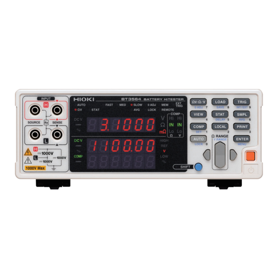
BT3564
BATTERY HiTESTER
Be sure to read this manual before using the instrument.
When using the instrument for the
first time
Names and Functions of Parts
Measurement
Oct. 2020 Revised edition 2
BT3564A961-02 20-10H
Troubleshooting
p.9
Maintenance and Service
p.21
Troubleshooting
Error Indication
HIOKI BT3564A961-02
Instruction Manual
p.3
p.173
p.173
p.175
EN
Advertisement
Table of Contents

Related Manuals for Hioki BT3564


Summary of Contents for Hioki BT3564
- Page 1 BT3564 Instruction Manual BATTERY HiTESTER Be sure to read this manual before using the instrument. p.3 When using the instrument for the Troubleshooting first time Names and Functions of Parts Maintenance and Service p.173 Measurement p.21 Troubleshooting p.173...
- Page 2 HIOKI BT3564A961-02...
-
Page 3: Table Of Contents
Auto-Ranging ..............29 Setting Sampling Rate ............30 Zero-Adjust Function ............30 Wiring Method for Zero-Adjustment ........30 Executing Zero-Adjustment..........31 Displaying Measurement Results ........35 Measurement Fault Detection ..........36 Overflow Display ..............37 BT3564A961-02 HIOKI BT3564A961-02... - Page 4 Input Signals............... 77 Output Signals ..............78 ERR Output ................ 79 Instrument Settings............. 80 Timing Chart ..............81 Internal Circuitry ..............83 Electrical Specifications............84 Connection Examples............84 External Control Q&A ............86 HIOKI BT3564A961-02...
- Page 5 Sample Programs ............158 ® To be prepared in Visual Studio 2017......158 ® Creation Procedure (Visual Basic 2017)......158 ® Sample Programs (Visual Basic 2017) ......160 ® Sample Programs (Visual C# 2017) ....... 162 HIOKI BT3564A961-02...
- Page 6 Appendix 6 Effect of Eddy Currents ..........A 8 Appendix 7 Calibration Procedure..........A 9 Appendix 8 Zero Adjustment ............A 10 Appendix 9 Test Lead Options .............A 15 Appendix 10 Rack Mounting ............A 17 Appendix 11 Dimensional Diagram..........A 19 Index ________________________________Index 1 HIOKI BT3564A961-02...
-
Page 7: Introduction
Introduction Introduction Thank you for purchasing the Hioki Model BT3564 Battery HiTester. To obtain maximum performance from the instrument, please read this manual first, and keep it handy for future reference. Be sure to also read the separate document "Operating Precautions" before use. -
Page 8: Verifying Package Contents
In particular, check the accessories, panel switches, and connectors. If damage is evident, or if it fails to operate according to the specifications, contact your authorized Hioki distributor or reseller. Use the original packing materials when transporting the instrument, if possible. -
Page 9: Safety Notes
The value currently being measured and indicated on the measuring instrument. dgt. (resolution) The smallest displayable unit on a digital measuring instrument, i.e., the input value that causes the digital display to show a "1" as the least-significant digit. HIOKI BT3564A961-02... -
Page 10: Usage Notes
• Do not place the instrument on an unstable or slanted surface. 50 mm or more 50 mm or more 10 mm or more Rear The instrument can be used with the stand. ( p.12) It can also be rack-mounted. Appendix ( p.A17) HIOKI BT3564A961-02... -
Page 11: Appendix 3 Measurement Values When Using Four-Terminal Measurement (Differences In Measurement Values Due To Measurement Leads Used)
Using the instrument in such conditions could cause an electric shock, so con- tact your authorized Hioki distributor or reseller for replacements. Measurement Precautions • To avoid electrical shock, be careful to avoid shorting live lines with the test leads. - Page 12 Handling the Test Leads and Cables • To avoid breaking the test leads and cables, do not bend or pull them. • Avoid stepping on or pinching cables, which could damage the cable insula- tion. HIOKI BT3564A961-02...
-
Page 13: Chapter 1 Overview
Chapter 1 Overview 1.1 Product Overview The Model BT3564 Battery HiTester measures battery internal resistance using a four-terminal, 1-kHz AC method, while simultaneously measuring DC voltage (electromotive force [emf]). The high-precision, fast measurement performance and extensive interface capabilities make these models ideal for incorporating into battery testing production lines. -
Page 14: Features
EXT I/O Interface EXT I/O and RS-232C interfaces are equipped as standard, supporting transfer rates up to 38,400 bps. Model BT3564 also supports GP-IB and analog output. Printing Measurement Values and Statistical Results Connect the printer to print measurement values and statistical calculation results. -
Page 15: Names And Functions Of Parts
Turns the power on and off (standby). Off (standby): On (cancel standby) On (press and hold for 1 second): Off (standby) (The main power switch is located on the back of the instrument.) "2.4 Turning the Power On and Off" ( p.18) HIOKI BT3564A961-02... -
Page 16: Appendix 8 Zero Adjustment
HIGH, LOW Indicates that absolute value comparator operation is enabled (while measuring), and also when setting. REF, % Indicates that relative value comparator operation is enabled (while measuring), and also when setting. Indicates the measured voltage value unit. HIOKI BT3564A961-02... - Page 17 However, this does not apply to Menu display. However, from a LOCAL Cancels remote control (RMT) and re- menu item display, changed set- enables key operations. tings canceled, accepted as the display returns to measurement display (except after Zero-Adjustment clear or resetting). HIOKI BT3564A961-02...
- Page 18 Connect here to use the EXT I/O interface. "Chapter 5 External Control (EXT I/O)" ( p.75) Side View Stand Can be opened to tilt the front panel upwards. Do not apply heavy downward pressure with the stand extended. The stand could be damaged. HIOKI BT3564A961-02...
-
Page 19: Menu Display Sequence (Shift > Enter)
p.20) Configuring the Absolute Reset display p.72) Value Judgment display p.53) Pressing this key returns to the previous item display. Settings on the menu item displays are applied and saved internally when changed. HIOKI BT3564A961-02... -
Page 20: Measurement Flowchart
Connecting the test leads to a test object. p.35) Reading the measured value For details about the functions that can be applied to measurement values such as comparator, trigger and averaging functions, refer to "Chapter 4 Applied Measurement" ( p.39). HIOKI BT3564A961-02... -
Page 21: Measurement Preparations
Seting the measurement settings ( p.21) Starting a measurement Verify that the instrument’s line frequency is correctly set when using it for the first time and after initialization following repair or recalibration. "2.5 Selecting the Line Frequency" ( p.20). HIOKI BT3564A961-02... -
Page 22: Connecting The Power Cord
(rear panel) is off ( Check that the power supply voltage (100 V to 240 V) is correct, and connect the power cord to the power inlet socket on the rear of the instrument. Plug the power cord into the AC outlet. HIOKI BT3564A961-02... -
Page 23: Connecting The Optional Test Leads
SENSE SENSE SOURCE SOURCE Black Black When clipping a thin line When clipping a thick line (Clip the line at the tip, (Clip the line at the serrated part of the deep, non-serrated part jaws.) of the jaws.) HIOKI BT3564A961-02... -
Page 24: Turning The Power On And Off
The instrument will start up in the standby state in which it was last turned off. (The instrument is shipped in the standby state.) Power on Turning the Power Off Turn off the main power switch on the rear of the instrument ( Power off HIOKI BT3564A961-02... - Page 25 (Sub display) Line frequency Interface The measurement display appears. Placing the Instrument in the Standby State Press and hold the power switch on the front of the instrument for approximately 1 second while it is in the operating state. HIOKI BT3564A961-02...
-
Page 26: Selecting The Line Frequency
• Changes in the power supply frequency occurring at other times will not be detected. • The power supply frequency will be set to either 50 Hz or 60 Hz, whichever is closer. HIOKI BT3564A961-02... -
Page 27: Chapter 3 Measurement
Before using the instrument for the first time, verify that it operates normally to ensure that no damage occurred during storage or shipping. If you find any damage, contact your authorized Hioki distributor or reseller. Before using the instrument, perform the following inspection to ensure that it is operating properly. -
Page 28: Basic Measurement Example
Red Lead Black Lead Example: Model 9770 Turn the main power switch on. "2.4 Turning the Power On and Off" ( p.18). "2.5 Selecting the Line Frequency" ( p.20). Cancel the standby state. "Cancelling the Standby State" ( p.19). HIOKI BT3564A961-02... - Page 29 Decrease the resistance measurement range. (SHIFT Lamp lit) Set the voltage measurement range. (for this example, the 10 V setting has been selected.) "Voltage measurement range" ( p.28) V lit Increase the voltage measurement range. Decrease the voltage measurement range. HIOKI BT3564A961-02...
- Page 30 • External conductor and external conductor conductor (The SHIFT indicator lights up.) Execute Zero-Adjust. After zero-adjustment, the display returns to the measurement mode. 0ADJ lit “Err.02” appears if Zero-Adjustment fails. Verify that the test lead tips are properly shorted, and try zero-adjustment again. HIOKI BT3564A961-02...
- Page 31 Read the measured resistance and voltage. Measured resistance value Measured voltage value "3.7 Displaying Measurement Results" ( p.35). "10.3 Error Indication" ( p.175). Please refer to "Measured value is unstable." of "Before returning for repair." ( p.173) as a measurement and attention. HIOKI BT3564A961-02...
-
Page 32: Selecting Measurement Mode
V” indicates the V mode is selected mode (Resistance measurement) V mode (Voltage measurement) The fastest measurements are provided by selecting the or V mode when measuring resistance or voltage, respectively. "Sampling time" ( p.166). HIOKI BT3564A961-02... -
Page 33: Setting Measurement Range
Increase the resistance measurement range. When the 300 m range is Decrease the resistance measurement range. selected Pressing the up or down keys while in auto-range mode will cancel auto-ranging, leaving the current measurement range as the manually set range. HIOKI BT3564A961-02... -
Page 34: Voltage Measurement Range
Increase the voltage measurement range. Decrease the voltage measurement range. When the 100 V range is selected V lit Increase the voltage measurement range. Decrease the voltage measurement range. When the 10 V range is selected V lit HIOKI BT3564A961-02... -
Page 35: Auto-Ranging
4 V peak 3000 10 A -100.0 to 3100.0 k 4 V peak 10 V -9.99999 to 9.99999 V 100 V -99.9999 to 99.9999 V 1000 V -999.999 to 999.999 V -1100.00 to -1000.00 V 1000.00 to 1100.00 V HIOKI BT3564A961-02... -
Page 36: Setting Sampling Rate
Before executing zero adjustment, connect the test leads (probes) as follows: 1. Connect SENSE-H to SENSE-L. 2. Connect SOURCE-H to SOURCE-L. 3. Connect the joined SENSE and SOURCE leads together as shown below. SENSE-H SENSE-L SOURCE-H SOURCE-L Connection Connection HIOKI BT3564A961-02... -
Page 37: Executing Zero-Adjustment
Short-circuit the test leads together. Proper zero adjustment is not possible with incorrect wiring. Example: Model L2107 Clip Type Leads Bring the "V" marks together at the Correct same position. SENSE SENSE SOURCE SOURCE Black Incorrect SOURCE SENSE SENSE SOURCE Black HIOKI BT3564A961-02... - Page 38 While inserting each SENSE (the the board. While inserting each SENSE (the side with a line) pin into the larger side of side with the surface) pin into the larger each elongate hole. side of each elongate hole. HIOKI BT3564A961-02...
- Page 39 3.6 Zero-Adjust Function (The SHIFT indicator lights up.) Zero-adjust display appears. 0ADJ lit After measurement, the measured value of the compensation applied by the zero-adjust function is displayed. The range of zero adjustment is up to ±1000 dgt. HIOKI BT3564A961-02...
- Page 40 V function, the 0ADJ indicator lights up or turns off according to the resistance measurement range zero-adjust state. • Zero-adjustment values are retained even when power is turned off. • The 0ADJ terminal of the EXT I/O connector also executes zero adjustment. "5.2 Signal Descriptions" ( p.76). HIOKI BT3564A961-02...
-
Page 41: Displaying Measurement Results
Measured resistance value In the V mode, the measured voltage value appears on the upper display. Measured voltage value Please refer to "Measured value is unstable." of "Before returning for repair." ( p.173). HIOKI BT3564A961-02... -
Page 42: Measurement Fault Detection
20 [for the 3 m and 30 m ranges, 2 ].) *The instrument may be unable to detect measurement faults when the mea- surement lead capacitance is greater than or equal to 1 nF. HIOKI BT3564A961-02... -
Page 43: Overflow Display
• The measured value is below the limit of the current measurement range • The test object impedance exceeds the input level (in the negative direction). • When the result of relative value calculation is smaller than -99.999%. HIOKI BT3564A961-02... - Page 44 3.7 Displaying Measurement Results HIOKI BT3564A961-02...
-
Page 45: Applied Measurement
Increase measurement precision Self-Calibration p.69) Output measurement values via the Measurement Value p.70) RS-232C interface according to trig- Output Function ger input timing Enable/disable key-press beeps Key Beeper Setting p.71) Re-initialize the instrument Reset Function p.72) HIOKI BT3564A961-02... -
Page 46: Comparator Function
(or reference value and tolerance) Selecting the voltage Selecting the voltage comparison method (absolute or relative value) for the comparator Specifying the voltage upper and lower thresholds (or reference value and tolerance) Applying your comparator settings Enabling the comparator function HIOKI BT3564A961-02... -
Page 47: Comparator Setting Example 1 (Upper And Lower Threshold Judgment)
Select the resistance measurement range (for this example, the 300 m range). Increase the resistance measurement range. Decrease the resistance measurement range. Select the voltage measurement range (for this example, the 100 V range). V lit Increase the resistance measurement range. Decrease the resistance measurement range. HIOKI BT3564A961-02... - Page 48 Press so that the indicated position blinks, and select the comparator mode (for this example, Auto). A flashing .... Auto comparator (default setting) .... Manual comparator Press so that the indicated position blinks, and select resistance. r flashing .....Resistance ....Voltage HIOKI BT3564A961-02...
- Page 49 (Press on a screen other than the upper/lower threshold setting display.) " Upper and Lower Thresholds Setting (by Reference Value and Tolerance)" ( p.52). Press so that the indicated position blinks, and select voltage. u flashing ..... Resistance (default setting) .... Voltage HIOKI BT3564A961-02...
- Page 50 V mode, you can verify comparator settings by pressing the VIEW key. " Switching Between Measurement Value and Comparator Setting Displays" ( p.56). Upper threshold value < Measured value Lower threshold value Measured value Upper threshold value Measured value < Lower threshold value HIOKI BT3564A961-02...
-
Page 51: Comparator Setting Example 2 (Reference Value And Tolerance Judgment)
Comparator function.) COMP not lit Select the V measurement mode. V lit Select the measurement range (for this example, the 3 range). lit Increase the resistance measurement range. Decrease the resistance measurement range. HIOKI BT3564A961-02... - Page 52 (IN), and beeps repeatedly when measurements go Hi or Lo. Press so that the indicated position blinks, and select the comparator mode (for this example, Auto). A flashing .... Auto comparator (default setting) .... Manual comparator HIOKI BT3564A961-02...
- Page 53 (Press on a screen other than the upper/lower threshold setting display.) To enter the result of statistical calculation value: STAT (Press on a screen other than the upper/lower threshold setting display.) " Upper and Lower Thresholds Setting (by Reference Value and Tolerance)" ( p.52). HIOKI BT3564A961-02...
- Page 54 Switch to the Ref/% threshold setting display, and specify the thresholds. For this example, Reference value: 4.2 V Tolerance: 0.5% numeric keypads Applies the settings and returns to the measurement display. The comparator function is enabled. COMP lit To cancel the settings: SHIFT HIOKI BT3564A961-02...
- Page 55 Measured value < Lower threshold value of setting range The instrument can also base judgments on the absolute value of measured voltage value (to prevent Lo judgments when the positive and negative terminals are connected backwards). "Configuring the Absolute Value Judgment Function (Voltage)" ( p.53) HIOKI BT3564A961-02...
-
Page 56: Comparator Judgment Beeper Setting
....Auto comparator (comparator results are always output [default setting]) ....Manual comparator (comparator results are output only when the MANU EXT I/ O input is enabled [ON]) The auto setting is appropriate for normal use. Use the manual/external setting when you need to control comparator judgment timing. HIOKI BT3564A961-02... -
Page 57: Comparator Threshold Method Selection
Lower threshold = reference value × (100 - tolerance [%]) / 100 Measured values are displayed as a percentage relative to the reference value, calcu- lated as follows: Relative value = (measured value - reference value) / reference value× 100 [%] HIOKI BT3564A961-02... -
Page 58: Upper And Lower Thresholds Setting (By Reference Value And Tolerance)
When using the numeric keypads Select a digit to change by mov- Press the numeric keys cor- ing the blinking location, then se- responding to the digits to lect the new numerical value. be entered. Select a digit Select numerical value HIOKI BT3564A961-02... -
Page 59: Configuring The Absolute Value Judgment Function (Voltage)
(resulting in a negative voltage mea- sured value), set the absolute value judgment function to "On." This function is configured on the menu screen. (The SHIFT indicator lights up.) The menu screen is displayed. HIOKI BT3564A961-02... -
Page 60: Enabling And Disabling The Comparator Function
SMPL key (Averaging setting) • SHIFT TRIG key (Trigger source setting) • SHIFT ENTER key (Menu display) • SHIFT STAT key (Delay setting) • Range keys When the comparator is enabled, auto-ranging is automatically disabled. HIOKI BT3564A961-02... -
Page 61: Comparator Judgment Results
With the relative value comparison method (thresholds defined by a reference value and tolerance), the upper and lower thresholds are calculated internally for comparison with measurements. Therefore, even if a relative display value is equal to a judgment threshold (tolerance limit), it may be judged Hi or Lo. HIOKI BT3564A961-02... -
Page 62: Switching Between Measurement Value And Comparator Setting Displays
Voltage measurement and comparator dis- play (Shows the measured voltage value and voltage comparator setting value) Measurement display switching is available only with the comparator enabled, and in the V mode. Use it to confirm comparator setting values. HIOKI BT3564A961-02... -
Page 63: Trigger Function
External, a measurement occurs each time an external trigger is applied. Con- tinuous measurement can be disabled via RS-232C or GP-IB interface sig- nals, in which case triggering occurs only when signaled by the external host (PC or PLC). " Triggering System Description" ( p.145). HIOKI BT3564A961-02... -
Page 64: Trigger Delay Settings
Applies the setting and returns to the Measurement display. To cancel the settings: SHIFT Disabling the Trigger Delay Function (The SHIFT indicator lights up.) The Trigger Delay setting display appears. Select (Sub display) The Trigger Delay is disabled. HIOKI BT3564A961-02... -
Page 65: Averaging Function
(Sub display) The Averaging Function is disabled. ( not lit) When the internal trigger is used for continuous measurement (free-run), the display shows the moving average. Otherwise, the display shows the integrat- ing average. "4.2 Trigger Function" ( p.57). HIOKI BT3564A961-02... -
Page 66: Statistical Calculation Functions
• When comparator, range or auto-ranging settings are changed while statisti- cal data is displayed, the display of Cp and CpK values changes to “- - . - -”. • When normal measurement values and relative display values (%) are mixed, correct calculation results cannot be obtained. HIOKI BT3564A961-02... - Page 67 • The Statistical Calculation function slows measurements when it is ON. Clearing Statistical Calculation Results The Statistical Calculation display appears. (Main display) (Sub display) The Clearing screen will appear. (Sub display) (press once) Clears statistical calculation results. HIOKI BT3564A961-02...
- Page 68 • Shorting the TRIG terminal to the ISO_COM of the EXT I/O connector exe- cutes the same operation. Confirming Statistical Calculation Results The Statistical Calculation display appears. The indication on the display changes as follows with each key-press. HIOKI BT3564A961-02...
- Page 69 Cp and CpK values changes to “- - . - -”. Sending Statistical Calculation Results to the Printer With the statistical calculation results displayed, press the key. PRINT The statistical calculation results are output to the optional printer. "Chapter 6 Printing" ( p.87). HIOKI BT3564A961-02...
-
Page 70: Memory Function
If an external trigger source is selected, one measurement is stored after each trigger event. In the internal triggering case, the first measurement val- ue after triggering is stored. Apply a trigger as many times as is necessary. HIOKI BT3564A961-02... - Page 71 When Reset is executed from the menu display When sending :SYSTem:RESet When sending When turning power on • When the measurement mode is set to or V, a measurement error value will be returned for functions that are not being measured. HIOKI BT3564A961-02...
-
Page 72: Key-Lock Function
• Even if the power supply is interrupted, the Key-Lock function is not can- celed. • The TRIG key remains operational. Disabling Key-Lock (The SHIFT indicator lights up.) Disable the Key-Lock function. (LOCK is not lit) When communicating by remote control, the remote control status is canceled. HIOKI BT3564A961-02... -
Page 73: Panel Save Function
• Delay setting • Auto-ranging setting • Zero-Adjust setting • Sampling rate setting • Averaging setting • Comparator settings • Key-Lock • Internal/External trigger setting • Statistical Calculation setting (The absolute value judgment function setting is not saved.) HIOKI BT3564A961-02... -
Page 74: Panel Load Function
• When selecting a Panel No. with the up/down RANGE keys, only the num- bers of previously saved panels appear. • Loading can also be executed using the TRIG signal and the LOAD0 to LOAD6 pins of the EXT I/O interface. " Input Signals" ( p.77). HIOKI BT3564A961-02... -
Page 75: Self-Calibration
Manual self-calibration Applies the setting and returns to the Measurement display. Self-calibration requires about 176 ms (power supply frequency: 50 Hz) or about 151 ms (power supply frequency: 60 Hz), during which measurement processing is temporarily suspended. HIOKI BT3564A961-02... -
Page 76: Measurement Value Output Function
• When external triggering is enabled, a measurement is performed and the value is sent after each trigger event. When internal triggering is enabled, the first value measured after triggering is sent. • The measurement output function is not applicable to the GP-IB interface or printer. HIOKI BT3564A961-02... -
Page 77: Key Beeper Setting
"1.4 Menu Display Sequence (SHIFT > ENTER)" ( p.13). (Main display) (Sub display) The current setting blinks. Select the key beeper state on the sub display. on..Key beeper enabled..Key beeper disabled. Applies the setting and returns to the Measurement display. HIOKI BT3564A961-02... -
Page 78: Reset Function
..Reset (initializes measurement settings other than those stored with Panel Save) ..System Reset (initialize all measurement settings) blinks. ENTER (Sub display) When SYS (system reset) is selected Executes the Reset. To cancel the settings: SHIFT System Reset also initializes Panel Save data. HIOKI BT3564A961-02... - Page 79 Calculation Results Interface RS-232C Baud Rate 9600 bps GP-IB Address GP-IB Delimiter Print Interval 0 (The interval print disabled) Error Output ASync Measurement Value Output Function EOM Output HOLD EOM Pulse Width 1 ms Comparator absolute value judgment function HIOKI BT3564A961-02...
- Page 80 4.12 Reset Function HIOKI BT3564A961-02...
-
Page 81: External Control (Ext I/O)
• Do not apply voltage or current to the EXT I/O terminals that exceeds their ratings. • When driving relays, be sure to install diodes to absorb counter-electromotive force. Be careful not to short-circuit • ISO_5V to ISO_COM. See: "5.2 Signal Descriptions" ( p.76) HIOKI BT3564A961-02... -
Page 82: Signal Descriptions
Do not connect to reserved pins. The connector frame is connected to (continuous with) both the instrument's case (the metal cabinet surrounding the instrument) and the power inlet's protec- tive ground pin. Note that the frame is not isolated from the ground. HIOKI BT3564A961-02... -
Page 83: Input Signals
CAL signal transitions from High to Low. Self-calibration takes about 176 ms (power supply frequency: 50 Hz) or about 151 ms (ower supply frequency: 60 Hz). When SLOW sampling is selected, the CAL signal is ignored. "4.9 Self-Calibration" ( p.69). HIOKI BT3564A961-02... -
Page 84: Output Signals
• The EOM and INDEX signals are initialized HIGH (OFF) at power on. • If it is not necessary to change the measurement conditions, set LOAD0 through LOAD6 to either Hi or Lo. • To avoid erroneous comparator judgments, both the PASS and FAIL signals should be checked. HIOKI BT3564A961-02... -
Page 85: Err Output
EOM Out- output is asynchronous with the TRIG signal and EOM output. ERR Output Low (On): Measurement fault condition (open test leads, or a bad put (ASYNC) contact) ERR Output High (Off): Test lead connections are normal HIOKI BT3564A961-02... -
Page 86: Instrument Settings
Go to the next step. (When PULSE is selected) The number representing the pulse width of the EOM signal will start blinking. Set the pulse width in ms. Or numeric keypads Applies the settings and returns to the Measurement display. HIOKI BT3564A961-02... -
Page 87: Timing Chart
Measuring Reference Signal Pulse Pulse * EOM Output End-of-Measurement HOLD HOLD Signal Comparator Result * When the EOM signal is set to PULSE, the signal will remain on only for the specified period upon com- pletion of conversion. HIOKI BT3564A961-02... - Page 88 About t5 calculation time In the following cases, add the indicated times to calculation time t5: When the Statistical Calculation function is enabled 0.3 ms When the reference value/tolerance method of 0.15 ms comparator decision is selected HIOKI BT3564A961-02...
-
Page 89: Internal Circuitry
5.4 Internal Circuitry 5.4 Internal Circuitry HIOKI BT3564A961-02... -
Page 90: Electrical Specifications
1 V (10 mA), 1.5 V (50 mA) Internally Isolated Output Voltage 4.5 to 5.0 V Power Output Maximum output current 100 mA External power input none Connection Examples Input Circuit Connection Examples BT3564 BT3564 Input Input Switch Connections Relay Connections BT3564 BT3564 Common Input Output Input... - Page 91 5.4 Internal Circuitry Output Circuit Connection Examples BT3564 BT3564 50mA max Output Output ISO_COM ISO_COM 30 V max Relay Connections LED Connection BT3564 BT3564 Output Output Active-Low Logic Output Output ISO_COM Active-Low Logic Output ISO_COM Wired OR BT3564 Common Output...
-
Page 92: External Control Q&A
PLC side. Can the measured values be acquired using a Please use the free software for acquiring measured values avail- footswitch during the free-run operation? able for download from our website. HIOKI BT3564A961-02... -
Page 93: Printing
• Parity........none • Stop bits ........ 1 • Flow control......none • Control codes ......Capable of directly printing plain text The optional printer model 9670 is no longer available. Their model 9670 printers can still use. HIOKI BT3564A961-02... -
Page 94: Connecting The Printer To The Instrument
Turn the instrument and printer RS-232C Cable Connector Pinouts 13 ........1 1 2 3 4 5 25 ........ 14 6 7 8 9 Printer (25-pin) Connector (Example) Model BT3564 (9-pin) Connector Signal Signal Function Function Name Name Receive Data... -
Page 95: Selecting The Interface
Set the print interval time. PRINT 0000 ......Interval printing is off. (Printing is carried out once when key is pressed.) 0001 to 3600 ....Sets the print interval time in seconds. numeric keypads Applies the setting and returns to the Measurement display. HIOKI BT3564A961-02... -
Page 96: Printing
From the Statistical Calculation display, press the PRINT key to print statistical calculation results. If no valid data exists, only the data count is printed. When only one valid data sample exists, standard deviation of sample and process capability indices cannot be printed. HIOKI BT3564A961-02... - Page 97 Comp Hi Comp IN Comp Lo Measurement values indicated as "Invalid" cannot be displayed by the instru- ment. The number of statistical calculation results indicated as “Valid” equals the count of valid data excluding measurement faults and overflows. HIOKI BT3564A961-02...
- Page 98 6.3 Printing HIOKI BT3564A961-02...
-
Page 99: Chapter 7 Analog Output
7.1 Connecting Analog Output Chapter 7 Analog Output The Model BT3564 is capable of generating analog output for measured resis- tance values. Changes in resistance values can be recorded by connecting the instrument's analog output to a logger or similar device. -
Page 100: Analog Output Specifications
• When using auto-ranging, the same resistance value may result in 1/10 (or 10 times) the output voltage due to range switching. It is recommend to set the range manually. • Output is set to 0 V when changing settings (range switching, etc.) and when the instrument is turned off. HIOKI BT3564A961-02... -
Page 101: Rs-232C/Gp-Ib Interfaces
Failure to do so could result in equip- ment malfunction or damage. • After connecting the communications cable, tighten the screws on the connec- tor securely. Failure to secure the connector could result in equipment mal- function or damage. HIOKI BT3564A961-02... -
Page 102: Overview And Features
*1. ANSI/IEEE Standard 488.1-1987, IEEE Standard Digital Interface for Programmable Instrumentation. *2. ANSI/IEEE Standard 488.2-1987, IEEE Standard Codes, Formats, Protocols, and Common Commands. *3. The situation in which the input buffer and the output queue become full, so that processing cannot continue. HIOKI BT3564A961-02... -
Page 103: Specifications
MTA (My Talk Address) is supported. All Service Request functions are supported. All Remote/Local functions are supported. No Parallel Poll function. All Device Clear functions are supported. All Device Trigger functions are supported. No Controller functions are supported. Operating Code: ASCII codes HIOKI BT3564A961-02... -
Page 104: Selecting The Connections And Protocol
Signal Name Signal Notes Common Unused No connection Receive Data Transmit Data Data Terminal Internally connected Ready to +5 V Signal Ground Unused No connection Request to Send Internally connected to +5 V Unused No connection Unused No connection HIOKI BT3564A961-02... - Page 105 Use a crossover cable with female 9-pin D-sub connectors. instrument to a PC Crossover Wiring Female 9-pin Female 9-pin Recommended cable: D-sub D-sub Model BT3564 end PC/AT-end Hioki Pin No. Pin No. Model 9637 RS-232C Cable (1.8 m) When connecting to a...
-
Page 106: Selecting The Communication Conditions
(Sub display) When selecting GP-IB, also set the Address and Message Terminator. (Sub display) Message Terminator setting (LF/CRLF) Address setting (0 to 30) Selects the item to set Setting Applies the settings and returns to the Measurement display. HIOKI BT3564A961-02... -
Page 107: Communication Methods
Messages can be either program messages, sent from the PC to the instrument, or response messages, sent from the instrument to the PC. Program messages Model BT3564 Response messages Message types are further categorized as follows: Command message Program messages... - Page 108 These commands are used to interrogate the instrument about the results of operations, measured values and the current states of instrument settings. As shown by the following examples, a query is formed by appending a question mark "?" after a program header. :FETCh? :MEASure:RESistance? HIOKI BT3564A961-02...
- Page 109 In a message consisting of both a header and data, the header is separated from the data by a space " ". :SYSTEM:ELOCK ON (3) Data Separator In a message containing multiple data items, commas are required to separate the data items from one another. HIOKI BT3564A961-02...
- Page 110 The instrument does not fully support IEEE 488.2. As much as possible, please use the data formats shown in the Reference section. Also, be careful to avoid constructing single commands that could overflow the input buffer or output queue. HIOKI BT3564A961-02...
-
Page 111: Output Queue And Input Buffer
If 256 bytes are allowed to accumulate in this buffer so that it becomes full, the GP-IB interface bus enters the waiting state until space is cleared in the buffer. The RS-232C interface will not accept data beyond 256 bytes. Ensure that the no command ever exceeds 256 bytes. HIOKI BT3564A961-02... -
Page 112: Status Byte Register
Service Request Enable Register. When any bit selected by the mask is set, bit 6 (MSS; the Master Summary Status) of the Status Byte Register is also set, which generates an SRQ (Service Request) message and dispatches a service request. HIOKI BT3564A961-02... - Page 113 This is the logical sum of Event Status Register 0. Service Request Enable Register (SRER) This register masks the Status Byte Register. Setting a bit of this register to 1 enables the corresponding bit of the Status Byte Register to be used. HIOKI BT3564A961-02...
-
Page 114: Event Registers
Bit 1 unused Bit 0 Operation Complete (GP-IB only) • This bit is set to 1 in response to an command. • It indicates the completion of operations of all messages up to the com- mand HIOKI BT3564A961-02... - Page 115 Bit 3 Unused V-Lo Voltage Low Comparator Result Bit 2 Unused R-Hi Resistance High Comparator Result Bit 1 End of Mea- INDEX R-IN Resistance IN Comparator Result surement Bit 0 End of Conver- R-Lo Resistance Low Comparator Result sion HIOKI BT3564A961-02...
- Page 116 Disables all keys, including the key. LOCAL Device CLear Clears the input buffer and the output queue. Selected Device Clears the input buffer and the output queue. Clear Group Execute When an external trigger occurs, processes Trigger one sample. HIOKI BT3564A961-02...
-
Page 117: Initialization Items
Remote state REMOTE off • Remote control can be canceled by pressing the SHIFT key and then the AUTO key. • If the Local Lock Out ( p.110) GP-IB command has been issued, the Remote state cannot be canceled. HIOKI BT3564A961-02... -
Page 118: Message List
Error description (an error occurs when executing messages in the following cases): Command Error ..When data is present after the command Query Error....When the response message exceeds 64 bytes Execution Error..When invalid character or numeric data is present HIOKI BT3564A961-02... -
Page 119: Device-Specific Commands
2 to 16 Sets the no. of samples to average :CALCulate:AVERage 2 to 16 Queries the no. of samples to average setting :CALCulate:AVERage? Comparator 1/ 0/ ON/OFF Sets comparator execution :CALCulate:LIMit:STATe ON/OFF Queries the comparator execution setting :CALCulate:LIMit:STATe? HIOKI BT3564A961-02... - Page 120 HI/ IN/ LO/ OFF/ ERR Queries resistance comparator judg- :CALCulate:LIMit:RESistance:RESult? ment results HI/ IN/ LO/ OFF/ ERR Queries voltage comparator judgment :CALCulate:LIMit:VOLTage:RESult? results 1/0/ON/OFF Sets the comparator absolute value :CALCulate:LIMit:ABS judgment function ON/OFF Queries the comparator absolute val- :CALCulate:LIMit:ABS? ue judgment function HIOKI BT3564A961-02...
- Page 121 ON/ OFF Queries the memory function state :MEMory:STATe? Clears instrument memory :MEMory:CLEAr 0 to 400 Queries the memory data count :MEMory:COUNt? [STEP] Queries the memory data :MEMory:DATA? Self-Calibration Executes self-calibration :SYSTem:CALibration 1/ 0/ ON/OFF Sets automatic self-calibration :SYSTem:CALibration:AUTO HIOKI BT3564A961-02...
- Page 122 Queries the header present setting :SYSTem:HEADer? ERR Output SYNChronous/ Sets error output timing :SYSTem:ERRor ASYNchronous SYNCHRONOUS/ Queries the error output timing setting :SYSTem:ERRor? ASYNCHRONOUS EOM Output :SYSTem:EOM:MODE <HOLD/PULSe> Selects the EOM output mode :SYSTem:EOM:MODE? (<HOLD/PULSE>) Queries the EOM output mode setting HIOKI BT3564A961-02...
- Page 123 <Measured resistance value> mode <Measured voltage val- ue> V mode <Measured resistance Executes a measurement and read :READ? value>, <Measured the measured values voltage value> V mode <Measured resistance value> mode <Measured voltage val- ue> V mode HIOKI BT3564A961-02...
-
Page 124: Message Reference
1 bit 0 Shows an example of an actual com- mand application. ESE 36 Example Command (Normally described with HEADER ON (Sets bits 5 and 2 of SESER) (except the HEADER command itself).) Command, Query Measurement instrument Response HIOKI BT3564A961-02... -
Page 125: Standard Commands
Queries the device manufacturer's name, model name and software version. Example Query IDN? Response HIOKI,BT3564,0,V1.00 The Device ID is Hioki BT3564, 0, software version 1.00. Note • The response message has no header. Internal Operation Command Initialize Device Syntax Command ... - Page 126 Note command is supported because it is defined in IEEE 488.2-1987, but because all Model BT3564 device-specific commands are sequential types, this command has no actual affect. Status and Event Control Commands Clear the Status Byte and Related Queues (Except the Output Queue)
- Page 127 2 bit 1 bit 0 unused unused unused bit 7 bit 6 bit 5 bit 4 bit 3 bit 2 bit 1 bit 0 Example Query ESR? Response Bit 5 of the SESR was set to 1. HIOKI BT3564A961-02...
- Page 128 Syntax Command Description Command Performs one measurement when external triggering is enabled. When Statistical Calculation is ON, imports calculation data. Wait 100 ms before applying the trigger with *TRG immediately after changing the measuring conditions during measurement. HIOKI BT3564A961-02...
-
Page 129: Device-Specific Commands
<0 to 255 (NR1)> Note :ESR0 :ESR1 For more information about the contents of the registers, :ESR0 :ESR1 see the description of the commands. :ESR0? Executing clears the contents of ESR0. :ESR1? Executing clears the contents of ESR1. HIOKI BT3564A961-02... - Page 130 Command :VOLTage:RANGe <-1000 to 1000> Query :VOLTage:RANGe? Response <measurement range(NR3)> <measurement range(NR3)>=10.00000E+0/100.0000E+0/1.00000E+3 Example Command :VOLT:RANG 15 Selects the voltage measurement range for measuring 15 V. Query :VOLT:RANG? 100.0000E+0 Response The voltage measurement range is fixed at 100 V. HIOKI BT3564A961-02...
- Page 131 10 sec. Select and Query the Sampling Rate setting Syntax Command :SAMPle:RATE <FAST/ MEDium/ SLOW> Query :SAMPle:RATE? Response <FAST/ MEDIUM/ SLOW> Example Command :SAMP:RATE MED Query :SAMP:RATE? MEDIUM Response HIOKI BT3564A961-02...
- Page 132 Response <ON or OFF> Example Command :CALC:LIM:STAT ON Query :CALC:LIM:STAT? Response Note • When the Comparator function is enabled, auto-ranging is disabled. • Switching the Comparator function on/off or changing its settings clears stored measurement data (memory function). HIOKI BT3564A961-02...
- Page 133 REF.....Decision by a reference value and tolerance. Example Command :CALC:LIM:RES:MODE REF Query :CALC:LIM:RES:MODE? Response (Voltage Measurement) Syntax Command :CALCulate:LIMit:VOLTage:MODE <HL/ REF> Query :CALCulate:LIMit:VOLTage:MODE? Response <HL/ REF> HL ....Decision by preset upper and lower thresholds. REF.....Decision by a reference value and tolerance. HIOKI BT3564A961-02...
- Page 134 Sets the upper threshold to 3.80000 V (with the 10 V range selected) Query :CALC:LIM:VOLT:UPP? Response 380000 Note The value is sent as a whole integer (count). To set 48.5003 V with the 100 V range, send the following: :CALC:LIM:VOLT:UPP 485003 HIOKI BT3564A961-02...
- Page 135 Sets the lower threshold to 3.60000 V (with the 10 V range selected) Query :CALC:LIM:VOLT:LOW? Response 360000 Note The value is sent as a whole integer (count). To set 45.9997 V with the 100 V range, send the following: :CALC:LIM:VOLT:LOW 459997 HIOKI BT3564A961-02...
- Page 136 Sets the reference value to 3.70000 V (with the 10 V range selected) Query :CALC:LIM:VOLT:REF? Response 370000 Note The value is sent as a whole integer (count). To set 47.0000 V with the 100 V range, send the following: :CALC:LIM:VOLT:REF 470000 HIOKI BT3564A961-02...
- Page 137 = 0 to 99.999 (NR2) Example Command :CALC:LIM:RES:PERC 0.3 Query :CALC:LIM:RES:PERC? Response 0.300 (Voltage Measurement) Syntax Command :CALCulate:LIMit:VOLTage:PERCent <Tolerance (%)> Query :CALCulate:LIMit:VOLTage:PERCent? Response <Tolerance (%)> <Tolerance (%)> = 0 to 99.999 (NR2) Example Command :CALC:LIM:VOLT:PERC 1.538 Query :CALC:LIM:VOLT:PERC? Response 1.538 HIOKI BT3564A961-02...
- Page 138 Syntax Command :CALCulate:LIMit:ABS <1, 0, ON or OFF> Query :CALCulate:LIMit:ABS? Response <ON or OFF> ON....Absolute value judgment function on OFF .... Absolute value judgment function off Note The absolute value is only taken for measured voltage values. HIOKI BT3564A961-02...
- Page 139 The upper limit of Cp and CpK is 99.99. Cp and CpK values greater than 99.99 are returned as 99.99. The lower limit of Cp and CpK is 0. Cp and CpK values less than 0 are returned as 0.00. Clear Statistical Calculation Results Syntax Command :CALCulate:STATistics:CLEAr HIOKI BT3564A961-02...
- Page 140 Measurement faults and out-of-range "OF" measurements are ignored for statisti- cal calculations. Query the Mean value (Resistance Measurement) Syntax Query :CALCulate:STATistics:RESistance:MEAN? Response <Mean (NR3)> Example Query :CALC:STAT:RES:MEAN? Response 295.76E-3 (Voltage Measurement) Syntax Query :CALCulate:STATistics:VOLTage:MEAN? Response <Mean (NR3)> Example Query :CALC:STAT:VOLT:MEAN? Response 1.3923E+0 HIOKI BT3564A961-02...
- Page 141 (Resistance Measurement) Syntax Query :CALCulate:STATistics:RESistance:MINimum? Response <Minimum value (NR3)>,<Data No. of Minimum value (NR1)> Example Query :CALC:STAT:RES:MIN? Response 294.88E-3,8 (Voltage Measurement) Syntax Query :CALCulate:STATistics:VOLTage:MINimum? Response <Minimum value (NR3)>,<Data No. of Minimum value (NR1)> Example Query :CALC:STAT:VOLT:MIN? Response 1.3923E+0,2 HIOKI BT3564A961-02...
- Page 142 :CALC:STAT:VOLT:LIM? Response 1,19,0,2 Query Standard Deviation (Resistance Measurement) Syntax Query :CALCulate:STATistics:RESistance:DEViation? Response < (NR3)>,< (NR3)> Example Query :CALC:STAT:RES:DEV? Response 0.82E-3,0.84E-3 (Voltage Measurement) Syntax Query :CALCulate:STATistics:VOLTage:DEViation? Response < (NR3)>,< (NR3)> Example Query :CALC:STAT:VOLT:DEV? Response 0.0000E+0,0.0000E+0 HIOKI BT3564A961-02...
- Page 143 Response <Cp (NR2)>,<CpK (NR2)> Example Query :CALC:STAT:VOLT:CP? Response 0.91, 0.00 Set and Query the Memory Function State Syntax Command :MEMory:STATe <1/0/ON/OFF> Query :MEMory:STATe? Response <ON/OFF> Example Command :MEM:STAT ON Query :MEM:STAT? Response Clear Instrument Memory Syntax Command :MEMory:CLEAr HIOKI BT3564A961-02...
- Page 144 • When the Memory function is enabled, auto-ranging is disabled. • When the measurement mode is set to or V, a measurement error value will be returned for functions that are not being measured. HIOKI BT3564A961-02...
- Page 145 PC to obtain measurement values. • Refer to "Measurement Value Formats" for format details of returned measure- ment values. • This function is not available when the GP-IB interface is selected. "4.10 Measurement Value Output Function" ( p.70). HIOKI BT3564A961-02...
- Page 146 :SYSTem:LFRequency? Response <AUTO/50/ 60> Example Command :SYST:LFR 60 Query :SYST:LFR? Response Set and Query the Key-Lock State Syntax Command :SYSTem:KLOCk <1, 0, ON or OFF> Query :SYSTem:KLOCk? Response <ON or OFF> Example Command :SYST:KLOC ON Query :SYST:KLOC? Response HIOKI BT3564A961-02...
- Page 147 Note Saved panel and backup settings are stored in the instrument’s EEPROM. Be aware that the number of times that the EEPROM can be rewritten is limited (to about a million times). HIOKI BT3564A961-02...
- Page 148 Command :SYSTem:TERMinator <0/ 1> Query :SYSTem:TERMinator? Response <0/ 1> 0 ..LF+EOI 1 ..CR ,LF+EOI Example Command :SYST:TERM 1 Query :SYST:TERM? Response Note The RS-232C delimiter is fixed as CR + LF. " Message Terminators" ( p.103). HIOKI BT3564A961-02...
- Page 149 Command All settings including saved panel settings are returned to factory defaults. Refer to “Reset Function” for details. Example Command :SYST:RES Note • If you want to preserve saved data, use the command instead. • The communication conditions are not initialized. HIOKI BT3564A961-02...
- Page 150 " Input Signals" ( p.77). bit4 bit3 bit2 bit1 bit0 IN4 (MA- IN2 (0ADJ) IN1 (CAL) IN0 (TRIG) (PRINT) Pin No. Note TRIG key and command are detected in the same way as the TRIG terminal signal. HIOKI BT3564A961-02...
- Page 151 :INITIATE:CONTINUOUS ON " Local Function" ( p.111). *2: The command cannot be used for triggering while awaiting a trigger af- :READ? ter issuing a command. In this case, use the TRIG terminal or TRIG key for triggering. HIOKI BT3564A961-02...
- Page 152 :INITIATE:IMMEDIATE • TRIG Termi- Trigger Delay Trigger Wait State Any of the fol- • TRIG Key lowing: • Measurement Trigger Delay • TRIG Termi- • TRIG Key Calculation Measurement Measured Value Output Calculation Measured Value Output HIOKI BT3564A961-02...
- Page 153 • When the trigger source is IMMediate, triggering occurs immediately before entering the Idle State. • When the trigger source is EXTernal, the Trigger Wait State is enabled to wait for an external trigger, and when a trigger occurs, one measurement is taken before entering the Idle State. HIOKI BT3564A961-02...
- Page 154 Syntax Command :TRIGger:DELay:STATe <1, 0, ON or OFF> Query :TRIGger:DELay:STATe? Response <ON or OFF> ON..Trigger delay enabled OFF ..Trigger delay disabled Example Command :TRIG:DEL:STAT ON Enables trigger delay. Query :TRIG:DEL:STAT? Response Trigger delay is enabled (ON). HIOKI BT3564A961-02...
- Page 155 Reads the most recent measurement. No trigger occurs. Example Query :FETC? 288.02E-3,1.3921E+0 Response (V mode) The last measured resistance is 288.02 m , and the last measured voltage is 1.3921 V. " Measurement Value Formats" ( p.151). HIOKI BT3564A961-02...
- Page 156 • When the trigger source is external, the command does not trigger mea- surement. :READ? • Wait 100 ms before applying the trigger with immediately after changing the measuring conditions during measurement. " Measurement Value Formats" ( p.151). HIOKI BT3564A961-02...
-
Page 157: Measurement Value Formats
• Unneeded zeroes to the left of the decimal point are replaced by blank space (20H). Example : _0001.36E-3 → ____1.36E-3 -0007.51E+0 → -___7.51E+0 ("_" indicates blanks space [20H].) ±* ***** The response will take the form of E+3 at voltages of -1000 V or less and 1000 V or greater. HIOKI BT3564A961-02... -
Page 158: Compatible Command With The Model 3560 Ac M Hitester
8.6 Message Reference Compatible Command with the Model 3560 AC m HiTESTER Model BT3564 Battery HiTester accepts all of the commands supported by the Hioki 3560 AC m HiTester. However the following differences result from the functional differences. Comparator Tables Up to 30 comparator settings can be saved with the Model 3560. - Page 159 For the instrument, the command header is set to off when the instrument is turned on or reset (including *RST). Message ([ ] = optional) Data Contents Differences ( ) = response data Model BT3564 Model 3560 Standard Commands IDN? <Manufacturer's Model name in response data: Model name in response data: name>,<Model name>,0,...
- Page 160 8.6 Message Reference Message ([ ] = optional) Data Contents Differences ( ) = response data Model BT3564 Model 3560 R/ RV :CSET:MODe :CSET:MODe? 1 to 126 (function not available) Specifies the comparator table :CSET:NUMBer number to set :CSET:NUMBer? <Upper threshold/ Lower Setting range: Setting range: 0 to 3.1000E+3...
- Page 161 8.6 Message Reference Message ([ ] = optional) Data Contents Differences ( ) = response data Model BT3564 Model 3560 ON/ OFF (function not available) Open terminal voltage is limit- :LIMit ed to 20 mV :LIMit? ON/ OFF (function not available)
- Page 162 30 m 300 m **** **** 3000 ± 1.0000E+8 1.0000E+8 Measurement Fault 1.0000E+9 1.0000E+9 Measured voltage value Measurement Range All sampling rates ±* **** ±** 50 V ± ± 1.0000E+8 Measurement Fault 1.0000E+9 HIOKI BT3564A961-02...
-
Page 163: Basic Data Importing Methods
Importing Data by TRIG Key or Terminal Initial :INITiate:CONTinuous OFF (disable continuous Setup measurement) :TRIGger:SOURce EXT (external triggering) Importing :READ? When triggered by the TRIG key or TRIG terminal, a measurement is taken and the result is transferred. HIOKI BT3564A961-02... -
Page 164: Sample Programs
This section describes an example of how to use the Windows development lan- ® guage Visual Studio 2017 Express Edition to operate the BT3564 unit from a PC via RS-232C, incorporate measurement values, and save measurement val- ues to a file. - Page 165 [Port Name] to the name of the port being used. Add code. Double click the [Start] control that was placed to display the code editor. Choose [ ] and exit Visual Stu- File Save All ® 2017. HIOKI BT3564A961-02...
-
Page 166: Sample Programs (Visual Basic 2017)
MessageBox.Show(ex.Message, "Error", MessageBoxButtons.OK, MessageBoxIcon.Error) End Try End Sub 'Set measurement conditions Private Sub SendSetting(ByVal sp As SerialPort) sp.WriteLine(":TRIG:SOUR IMM" 'Select internal triggering sp.WriteLine(":INIT:CONT ON") 'Continuous measurement ON Catch ex As Exception MessageBox.Show(ex.Message, "Error", MessageBoxButtons.OK, MessageBoxIcon.Error) End Try End Sub HIOKI BT3564A961-02... - Page 167 (e) Opens the “data.csv” file. However, if a file with this name already exists, the previous “data.csv” will be deleted and a new file created. (f) Sends the command to perform one measurement and return that measurement result to the com- puter. HIOKI BT3564A961-02...
-
Page 168: Sample Programs (Visual C# ® 2017)
SerialPort1.StopBits = StopBits.One; SerialPort1.NewLine = "\r\n"; //Terminator setting......(c) SerialPort1.ReadTimeout = 2000; //2 seconds time out......(d) SerialPort1.Open(); //Open a port SendSetting(); //Instrument settings sw = new StreamWriter(@"data.csv"); //Create text file to be saved.....(e) for (i = 0; i < 10; i++) HIOKI BT3564A961-02... - Page 169 = true; catch (Exception ex) MessageBox.Show(ex.Message); //Set measurement conditions private void SendSetting() SerialPort1.WriteLine(":TRIG:SOUR IMM");//Select internal triggering SerialPort1.WriteLine(":INIT:CONT ON"); //Continuous measurement ON catch (Exception ex) MessageBox.Show(ex.Message); //Close program when Button2 is pressed private void button2_Click(object sender, EventArgs e) Dispose(); HIOKI BT3564A961-02...
- Page 170 8.8 Sample Programs HIOKI BT3564A961-02...
-
Page 171: Chapter 9 Specifications
Approx. 215W X 80H X 329D mm (8.46”W X 3.15”H X 12.95”D) (excluding protruding parts) Mass Approx. 2.6 kg (91.7 oz.) Product warranty period 3 years Connector, cable, etc: Not covered by warranty Accessories and options ( p.2) HIOKI BT3564A961-02... -
Page 172: Basic Specifications
39 ms 257 ms Tolerance for SLOW sampling is ±5 ms, and ±1 ms for other sampling rates Values within parentheses are line frequency settings Total measurement time Overall time required for measurement: Response time + sampling time HIOKI BT3564A961-02... - Page 173 • If the measured value exceeds the measurement circuit amp’s input range (if the impedance value exceeds the range) Measurement fault detection (contact check) Detected information: SOURCE HIGH-LOW connection faults SENSE HIGH-LOW connection faults Error displays: “- - - - -” HIOKI BT3564A961-02...
-
Page 174: Accuracy
1 year period Guaranteed accuracy 1 year period after adjustment made by Hioki Guaranteed accuracy for 23°C ± 5°C (73°F ± 9°F), 80% RH or less (no condensation) temperature and humidity Warm-up time At least 30 minutes, after zero adjustment... - Page 175 Effect of radiated Resistance measurement: ±10% rdg. ±8000 dgt. at 10 V/m radio-frequency Voltage measurement: ±0.01% rdg. ±100 dgt. at 10 V/m electromagnetic field Effect of conducted Resistance measurement: ±0.5% rdg. ±1000 dgt. at 3 V radio-frequency electromagnetic field HIOKI BT3564A961-02...
-
Page 176: Functions
Calculations: Total data counts, valid data counts, maximum, minimum, average, standard deviation, population standard deviation and process capability indices (Cp and CpK) Calculations trigger: Statistical calculation of measured values initiated by EXT I/O signals, key or remote command HIOKI BT3564A961-02... - Page 177 * Measurement conditions can be saved and loaded by specifying a panel number. Reset Reset method: Reset/System reset * System Reset also initializes the panel save data Display device HIOKI BT3564A961-02...
-
Page 178: External Interfaces
(temperature coefficient ±0.02% f.s./°C) Conditions of accuracy guarantee:Temperature and humidity range 23 ± 5°C (73 ± 9°F), 80% RH or less (non-condensating) Warm-up time of at least 30 minutes Response time: Resistance measurement response time + sampling time + 1 ms HIOKI BT3564A961-02... -
Page 179: Maintenance And Service
• The fuse is housed in the power unit of the instrument. If the power does not turn on, the fuse may be blown. If this occurs, a replacement or repair cannot be performed by customers. Please contact your authorized Hioki distributor or reseller. - Page 180 Custom Test Leads"( p.A1) Are you using multiple Model Interference between measurement signals BT3564 instruments to make simul- may cause measured values to vary. taneous measurements? • Take care to keep probes' forked loops from overlapping (at the battery being measured).
-
Page 181: Cleaning
• Any of the SOURCE-H, SOURCE-L, SENSE-H or SENSE-L leads may be discon- nected or poorly connected • The probe may have a high contact resistance " Measurement Fault Detection"( p.36) • The contact failure circuit protection fuse may have blown due to test lead damage, excessive wear, or impurities. HIOKI BT3564A961-02... - Page 182 10.3 Error Indication HIOKI BT3564A961-02...
-
Page 183: Appendix
SOURCE-H SENSE-H Resistance Probe tip and connection points (Battery) SOURCE-L SENSE-L • When connecting to a test object, connect SOURCE-H and SOURCE-L toward the outside, and SENSE-H and SENSE-L toward the inside. SOURCE-H SENSE-H Resistance (Battery) SENSE-L SOURCE-L HIOKI BT3564A961-02... - Page 184 and 30 m ranges, where the effects of eddy currents are more pro- nounced. • Avoid the use of metal plates (short bars) as a zero-adjustment jig as the plate's resistance value will introduce an error component. HIOKI BT3564A961-02...
- Page 185 It is recommended to use a stranded cable with a conductor thickness of AWG 22 (0.3SQ) or greater. • To avoid short-circuit accidents, connect the probe's banana terminals to the instrument before connecting the probes to the battery. HIOKI BT3564A961-02...
-
Page 186: Appendix 2 Ac Four-Terminal Method
"- - - - -" within the measured resistance field. For more information on abnormal measurements, see Section " Measurement Fault Detection" ( p.36). HIOKI BT3564A961-02... - Page 187 Parallel pins Coaxial pins Example: The model L2100/L2110 (Example: The model 9770) Pin distance: 2.5 mm Pin distance: 0.6 mm +Terminal -Terminal +Terminal -Terminal Lead-acid battery Lead-acid battery Equipotential line Equipotential line Potential gradient Potential gradient V (voltage detected):A>B HIOKI BT3564A961-02...
-
Page 188: Appendix 4 Synchronous Detection System
When synchronous detection is applied to both v1 and v2, they are expressed as follows: v1 X v2 = 1/2ABcos - 1/2ABcos (2 The first term indicates effective resistance. The second term is attenuated by the LPF. The instrument displays the first term. HIOKI BT3564A961-02... -
Page 189: Appendix 5 Configuration And Extension Of The Test Leads
Appendix 5 Configuration and Extension of the Test Leads Appendix 5 Configuration and Extension of the Test Leads The test lead extension is normally performed by Hioki. If you want extension performed, contact your authorized Hioki distributor or reseller. Observe the following points when extending test leads: •... -
Page 190: Appendix 6 Effect Of Eddy Currents
The influence of eddy currents is a phe- nomenon unique to ohmmeters that measure resistance with AC power. To protect the test lead from such effects, keep metallic parts, including metallic plates, at a suitable distance from the test lead (branched section). HIOKI BT3564A961-02... -
Page 191: Appendix 7 Calibration Procedure
(DC resistance) does not equal the effective resistance (real part of impedance, displayed on the instrument). • For connection of a standard resistor to the instrument, see the figure below. Model BT3564 Standard SOURCE - Hi Resistor... - Page 192 SOURCE-H will go to SOURCE-L but not to the lead of SENSE-H or SENSE-L. This enables the voltage between SENSE-H and SENSE-L to be kept accurately at 0 V, and appropriate zero adjustment becomes possible. HIOKI BT3564A961-02...
- Page 193 Hi and Lo for connection Resistance between Short SENSE-H and SENSE-L Measurement current Short flow path Voltage occurring be- I × R tween SENSE-H and Short SENSE-L As connection method for Correct Wrong zero adjustment HIOKI BT3564A961-02...
- Page 194 Table 2: Clip type lead connection methods used during zero adjustment Wrong Correct SOURCE SENSE SENSE SENSE Connection method SENSE SOURCE SOURCE SOURCE Black Black Tip of lead Equivalent circuit Deformed equiva- lent circuit As connection meth- od for zero adjust- Correct Wrong ment HIOKI BT3564A961-02...
- Page 195 If connection is made using If connection is made using Z5038 0 ADJ Board metal board or similar object Pattern Tip of lead (conductive layer) Equivalent circuit Deformed equiva- lent circuit As connection meth- od for zero adjust- Correct Wrong ment HIOKI BT3564A961-02...
- Page 196 Then, you need to make the connection as shown in Table 1 (a) and perform zero adjustment. However, if a Hioki product is used, even in AC resistance measurement, if the ...
-
Page 197: Appendix 9 Test Lead Options
ICs mounted on boards. Resis- tance can be correctly measured even with small test objects. Bifurcation-to-probe length: approx. 250 mm Plug-to-bifurcation length: approx.400 mm Between pin bases: 0.2 mm Tip pin 250 mm 400 mm *Tip pins can be exchanged ahead. HIOKI BT3564A961-02... - Page 198 Plug-to-bifurcation length: approx. 850 mm Between pin bases: 2.5 mm Between pin bases: 2.5 mm 300 mm 850 mm 750 mm 850 mm Tip pin Tip pin *Tip pins can be exchanged ahead. *Tip pins can be exchanged ahead. HIOKI BT3564A961-02...
-
Page 199: Appendix 10 Rack Mounting
(Feet: M3 x 6 mm, Sides: M4 x 6 mm) _________ Rack Mounting Plate Template Diagram and Installation Procedure Rack Mounting Plate (JIS) Rack Mounting Plate (EIA) Spacer (Two Required) HIOKI BT3564A961-02... - Page 200 Installing the spacers on both sides of the instrument, affix the Rack Mounting Plate with the M4 x 10 mm screws. M4 x 10 mm When installing into the rack, reinforce the installation with a commercially available support stand. Spacers HIOKI BT3564A961-02...
-
Page 201: Appendix 11 Dimensional Diagram
Appendix 11 Dimensional Diagram Appendix 11 Dimensional Diagram 211 mm (8.31”) 75.5 mm (2.97”) 23 mm 34 mm 20.5 mm (0.91”) (1.34”) (0.81”) 215 mm (8.46”) 80 mm (3.15”) HIOKI BT3564A961-02... - Page 202 Appendix 11 Dimensional Diagram HIOKI BT3564A961-02...
-
Page 203: Index
..........57, 81 Damage ............173 Interval printing ..........89, 90 Data Format ............104 Decimal numeric data ........104 Device-specific command ......113, 123 dgt..............3, 168 Judge ..............40 Displayed value ...........29 Judgment beeper ..........50 Judgment results .......... 55, 78 HIOKI BT3564A961-02... - Page 204 Power supply frequency ....6, 16, 20, 165 Turning the power off ......... 18 Power supply voltage ......6, 18, 165 Turning the power on/off ........18 POWER switch ............. 9 PRINT ..............78 Printer ............11, 87 HIOKI BT3564A961-02...
- Page 205 Index Upper and lower thresholds ......51, 52 Voltage measurement .........26 Warm-up ...........5, 18, 69, 168 Zero-Adjustment ......11, 30, 34, A10 HIOKI BT3564A961-02...
- Page 206 Index HIOKI BT3564A961-02...
- Page 207 HIOKI BT3564A961-02...
- Page 208 HIOKI BT3564A961-02...
- Page 209 HIOKI BT3564A961-02...
- Page 210 HIOKI BT3564A961-02...
Need help?
Do you have a question about the BT3564 and is the answer not in the manual?
Questions and answers
How to change decimal point in voltage reading
You cannot change the decimal point in voltage readings on the Hioki BT3564. Numerical values are returned without a decimal point in standard responses. For scientific notation, the format is fixed (e.g., ±*.*E+0), and formatting like decimal placement is handled automatically by the device.
This answer is automatically generated