Carrier 38APS025-065 Installation Instructions Manual
Gemini select
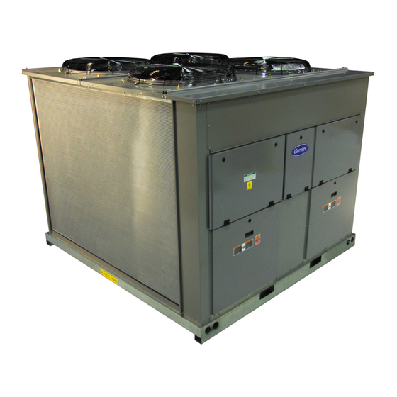
air-cooled condensing units with puron refrigerant (r-410a) 50/60 hz
Hide thumbs
Also See for 38APS025-065:
- Installation instructions manual (134 pages) ,
- Product data (106 pages) ,
- Installation instructions (4 pages)
Table of Contents
Advertisement
Quick Links
See also:
Product Data
Air-Cooled Condensing Units with PURON
CONTENTS
SAFETY CONSIDERATIONS . . . . . . . . . . . . . . . . . . . . . . 1
INSTALLATION . . . . . . . . . . . . . . . . . . . . . . . . . . . . . . . . 1-37
Step 1 — Inspect Shipment . . . . . . . . . . . . . . . . . . . . . . 1
Step 2 — Rig and Place Unit . . . . . . . . . . . . . . . . . . . . . 1
• DOMESTIC UNITS
• EXPORT UNITS
• PLACING UNITS
Step 3 — Make Refrigerant Piping
Connections . . . . . . . . . . . . . . . . . . . . . . . . . . . . . . . . . . 18
• SIZE REFRIGERANT LINES
• LIQUID LINE SOLENOID VALVE
• THERMOSTATIC EXPANSION VALVES
• LIQUID LINE FILTER DRIER
• LONG LINE APPLICATIONS
• HOT GAS BYPASS
• FINAL CONNECTION AND LEAK TEST
• EVACUATION AND DEHYDRATION
Step 4 — Make Electrical Connections . . . . . . . . . . 28
• POWER SUPPLY
• POWER WIRING
• CONTROL POWER
• FIELD CONTROL WIRING
Step 5 — Install Accessories . . . . . . . . . . . . . . . . . . . . 37
• LOW-AMBIENT OPERATION
• MISCELLANEOUS ACCESSORIES
SAFETY CONSIDERATIONS
Installing, starting up, and servicing this equipment can be
hazardous due to system pressures, electrical components, and
equipment location (roofs, elevated structures, etc.).
Only trained, qualified installers and service mechanics
should install, start up, and service this equipment.
Untrained personnel can perform basic maintenance func-
tions, such as cleaning coils. All other operations should be
performed by trained service personnel.
When working on the equipment, observe precautions in the
literature, and on tags, stickers, and labels attached to the
equipment and any other safety precautions that may apply.
• Follow all safety codes.
• Wear safety glasses and work gloves.
• Use care in handling, rigging, and setting bulky
equipment.
WARNING
Open all remote disconnects before servicing this equip-
ment. Failure to do so could result in personal injury from
electric shock.
Manufacturer reserves the right to discontinue, or change at any time, specifications or designs without notice and without incurring obligations.
Catalog No. 04-53380012-01
Installation Instructions
Page
Printed in U.S.A.
38APS025-065, 38APD025-130
Puron refrigerant (R-410A) systems operate at higher pres-
sures than standard R-22 systems. Do not use R-22 service
equipment or components on Puron refrigerant equipment.
If service equipment is not rated for Puron refrigerant,
equipment damage or personal injury may result.
INSTALLATION
Step 1 — Inspect Shipment —
age upon arrival. If damage is found, immediately file a claim
with the shipping company. Verify proper unit delivery by
checking unit nameplate data and the model number nomen-
clature shown in Fig. 1. See Tables 1-4 for unit physical data.
Step 2 — Rig and Place Unit —
signed for overhead rigging, and it is important that this meth-
od be used. Lifting holes are provided in the frame base rails. It
is recommended to use shackles in the lifting holes (see rigging
label on the unit and Fig. 2 and 3 for rigging weights and center
of gravity). All panels must be in place when rigging.
IMPORTANT: To maintain unit stability while lifting,
use 4 cables, chains or straps of equal length. Attach one
end of each cable to shackle attachment point and the
other end of each cable to the overhead rigging point.
Use spreader bars or frame to keep the cables, chains, and
straps clear of the unit sides. Leave standard coil protection
packaging in place during rigging to provide protection to
coils. Remove and discard all coil protection after rigging ca-
bles are detached.
All panels must be in place when rigging. Failure to com-
ply could result in equipment damage.
For unit sizes 025 to 060 when handling with a forklift,
handle only through fork pocket holes. Failure to follow
this caution could result in equipment damage or personal
injury.
For unit sizes 065 to 130, do not forklift the unit unless unit
is attached to a skid designed for forklifting. Failure to fol-
low this caution could result in equipment damage or per-
sonal injury.
Form 38AP-7SI
Pg 1
GEMINI™ SELECT
Refrigerant (R-410A)
®
50/60 Hz
CAUTION
Inspect unit for dam-
All units are de-
CAUTION
CAUTION
CAUTION
7-11
Replaces: 38AP-6SI
Advertisement
Table of Contents

Related Manuals for Carrier 38APS025-065


Summary of Contents for Carrier 38APS025-065
-
Page 1: Installation Instructions
GEMINI™ SELECT 38APS025-065, 38APD025-130 Air-Cooled Condensing Units with PURON Refrigerant (R-410A) ® 50/60 Hz Installation Instructions CONTENTS CAUTION Page SAFETY CONSIDERATIONS ..... . 1 Puron refrigerant (R-410A) systems operate at higher pres- INSTALLATION . -
Page 2: Installation
DOMESTIC UNITS — Standard 38AP unit packaging con- 4 x 24 in. perimeter support ASTM “C” channels between unit sists of coil protection only. Skids are not provided. If overhead and the isolators are recommended with a minimum of 4 chan- rigging is not available at the jobsite, place the unit on a skid or nels per unit. - Page 3 Table 1 — 38AP025-050 Unit Physical Data — English 38AP UNIT SIZE NOMINAL CAPACITY, 50/60 Hz (tons) 21/25 23/27 25/30 33/40 42/50 CIRCUIT Dual Single Dual Single Dual Single Dual Single Dual Single OPERATING WEIGHTS (lb) Standard 1095 1077 1258 1240 1264 1246...
- Page 4 Table 2 — 38AP060-130 Unit Physical Data — English 38AP UNIT SIZE NOMINAL CAPACITY, 50/60 Hz (tons) 50/60 54/65 58/70 67/80 75/90 83/100 96/115 108/130 CIRCUIT Dual Single Dual Dual Dual Dual Dual Dual OPERATING WEIGHTS (lb) Standard 2227 2561 2450 2610 2835...
- Page 5 Table 3 — 38AP025-050 Unit Physical Data — SI 38AP UNIT SIZES NOMINAL CAPACITY 50/60 Hz (kW) 73/88 79/95 88/105 117/141 146/176 CIRCUIT Dual Single Dual Single Dual Single Dual Single Dual Single OPERATING WEIGHTS (kg) Standard With Low Sound Option REFRIGERANT CHARGE (kg) Total* 11/—...
- Page 6 Table 4 — 38AP060-130 Unit Physical Data — SI 38AP UNIT SIZES NOMINAL CAPACITY 50/60 Hz (kW) 176/211 190/228 205/246 234/281 264/316 293/351 337/404 381/457 CIRCUIT Dual Single Dual Dual Dual Dual Dual Dual OPERATING WEIGHTS (kg) Standard 1010 1162 1111 1184 1286...
- Page 7 38APS Unit (lb) 38APS Unit (kg) 38APS OPERATIONAL CORNER WEIGHT 38APS OPERATIONAL CORNER WEIGHT TOTAL TOTAL UNIT UNIT WEIGHT WEIGHT SIZE SIZE 1089 1255 1261 1998 2007 2594 1177 38APD Unit (lb) 38APD Unit (kg) 38APD OPERATIONAL CORNER WEIGHT 38APD OPERATIONAL CORNER WEIGHT TOTAL TOTAL...
- Page 8 "#!$%&&' 2633 1194 2733 1240 SIZES 025 TO 060 SIZES 065 TO 130 "#!$%)() Fig. 3 — Rigging Labels "#!$%&#( LEGEND 4 x 24 in. ASTM “C” ASTM — American Society for Testing and Materials CHANNEL Fig. 4 — Perimeter Support Channel...
- Page 9 a38-7101...
- Page 10 a38-7224...
- Page 12 a38-7104...
- Page 14 Outdoor Fan Layout OFM1 OFM1 OFM3 OFM1 OFM1 OFM5 OFM3 OFM3 OFM2 OFM2 OFM6 OFM2 OFM2 OFM4 Top View Top View Top View Top View Sizes 025-030 Sizes 040-050 Sizes 060-070 Size 080 OFM3 OFM7 OFM1 OFM3 OFM5 OFM1 OFM1 OFM3 OFM5 OFM7...
- Page 15 40RU a38-7237 LEGEND NOTES: 1. All piping must follow standard refrigerant piping techniques. Refer to Carrier System LLSV — Liquid Line Solenoid Valve Design Manual for details. NEC — National Electrical Code 2. All wiring must comply with the applicable local and national codes.
- Page 16 NOTES: LEGEND 1. All piping must follow standard refrigerant piping techniques. Refer to Carrier System LLSV — Liquid Line Solenoid Valve Design Manual for details. NEC — National Electrical Code 2. All wiring must comply with the applicable local and national codes.
- Page 17 AHRI Standard 710. 2. All pipe sizes are OD inches. Equivalent sizes in millimeters follow: 12.7 15.9 22.2 28.6 3. Thermostatic expansion valve (TXV) is provided with all 40RU fan coil units. Contact your Carrier representative for appropriate TXV size.
-
Page 18: Connections
(22.9 m) for all units. Size suction lines in accordance with evaporator size is exceeded per Tables 7A and 7B. See Table 6 and Fig. 13. Fig. 14 (for 38APD025-130 dual-circuit units), or Fig. 15 (for 38APS025-065 single-circuit units). a38-7132 LEGEND D PIPE DIAMETER 38AP —... - Page 19 Table 6 — Refrigerant Piping Requirements 38APS025-050 Single-Circuit Units (60 Hz) TOTAL LINEAR LENGTH OF INTERCONNECTING PIPE, ft (m) CONN 0-25 25-50 50-75 75-100 100-125 125-150 150-175 175-200 38APS UNIT SIZE (0-7.6) (7.6-15.2) (15.2-22.9) (22.9-30.5) (30.5-38.1) (38.1-45.7) (45.7-53.3) (53.3-61.0) (in.) 38APD025-100 Dual-Circuit Units (60 Hz) TOTAL LINEAR LENGTH OF INTERCONNECTING PIPE, ft (m) CONN...
- Page 20 Table 6 — Refrigerant Piping Requirements (cont) 38APS025-050 Single-Circuit Units (50 Hz) TOTAL LINEAR LENGTH OF INTERCONNECTING PIPE, ft (m) CONN 0-25 25-50 50-75 75-100 100-125 125-150 150-175 175-200 38APS UNIT SIZE (0-7.6) (7.6-15.2) (15.2-22.9) (22.9-30.5) (30.5-38.1) (38.1-45.7) (45.7-53.3) (53.3-61.0) (in.) 38APD025-100 Dual-Circuit Units (50 Hz) TOTAL LINEAR LENGTH OF INTERCONNECTING PIPE, ft (m)
- Page 21 Table 6 — Refrigerant Piping Requirements (cont) 38APS025-65 Single-Circuit Units Double Suction Riser (60 Hz) TOTAL LINEAR LENGTH OF INTERCONNECTING PIPE, ft (m) CONN 0-25 25-50 50-75 75-100 100-125 125-150 150-175 175-200 38APS UNIT SIZE (0-7.6) (7.6-15.2) (15.2-22.9) (22.9-30.5) (30.5-38.1) (38.1-45.7) (45.7-53.3) (53.3-61.0)
- Page 22 Table 6 — Refrigerant Piping Requirements (cont) 38APS025-65 Single-Circuit Units Double Suction Riser (50 Hz) TOTAL LINEAR LENGTH OF INTERCONNECTING PIPE, ft (m) CONN 0-25 25-50 50-75 75-100 100-125 125-150 150-175 175-200 38APS UNIT SIZE (0-7.6) (7.6-15.2) (15.2-22.9) (22.9-30.5) (30.5-38.1) (38.1-45.7) (45.7-53.3) (53.3-61.0)
-
Page 23: Liquid Line Solenoid Valve
See Fig. 14 (for 38APD025-130 dual-circuit units), or Fig. 15 CAUTION (for 38APS025-065 single-circuit units). Refer to Table 5. THERMOSTATIC EXPANSION VALVES — All 38AP The 38AP unit is shipped with a nitrogen holding charge. -
Page 24: Liquid Line Solenoid Valve
SECTION 2 SOLENOID VALVE† SECTION 1 LIQUID LINE SECTION 2 SOLENOID VALVE† *Field-supplied. †Field-supplied when required. See Tables 7A and 7B. Fig. 15 — Required Location of Solenoid Valves and Recommended Filter Drier and Sight Glass Locations for 38APS025-065 Single-Circuit Units... - Page 25 SECTION a38-7121 LEGEND TXV — Thermostatic Expansion Valve TYP — Typical NOTE: For units with single condensate pan, lower coil section is first on, last off. Fig. 17 — Typical Piping Connections for Face Split Coils for 38APS025-065 Single-Circuit Units...
-
Page 26: Liquid Line Solenoid Valve
Table 7A — Requirements for Installation of Liquid Line Solenoid Valve MAXIMUM ALLOWABLE EVAPORATOR SURFACE AREA 38AP UNIT WITHOUT LIQUID LINE SOLENOID VALVE (sq ft) CIRCUIT SIZE 4-Row, in. Tube 6-Row, in. Tube 8-Row, in. Tube 3-Row, in. Tube 4-Row, in. -
Page 27: Liquid Line Solenoid Valve
Table 7B — Requirements for Installation of Liquid Line Solenoid Valve (SI) MAXIMUM ALLOWABLE EVAPORATOR SURFACE AREA 38AP UNIT WITHOUT LIQUID LINE SOLENOID VALVE (sq m) CIRCUIT SIZE 4-Row, in. Tube 6-Row, in. Tube 8-Row, in. Tube 3-Row, in. Tube 4-Row, in. -
Page 28: Step 4 — Make Electrical Connections
Class 1 AC service wiring. Do abuse and may adversely affect Carrier warranty. not abrade, cut, or nick the outer jacket of the cable. Do not pull or draw cable with a force that may harm the physical or elec- trical properties. -
Page 29: Power Supply
a38-7122 LEGEND c. Incoming wire size range for non-fused disconnect with MCA up to 100 amps is 14 AWG to 1/0. EQUIP GND — Equipment Ground d. Incoming wire size range for non-fused disconnect with MCA from — National Electrical Code 100.1 amps to 200 amps is 6 AWG to 350 kcmil. - Page 30 TERMINAL STRIP REMOTE ON/OFF COOL 2 a38-7235 COOL 1 *LLSV-A2 for 38APS025-065 single circuit units (optional). Fig. 21— Constant Volume Application Wiring Diagram 2-Stage Thermostat Control — 38AP025-030 Units without Digital Scroll Option TERMINAL STRIP REMOTE ON/OFF COOL 2 a38-7236 COOL 1 *See Fig.
- Page 31 TERMINAL STRIP REMOTE ON/OFF *See Fig. 20 for SAT and MAT/RAT location. †LLSV-A2 for 38APS025-065 single circuit units (optional). Fig. 23 — Constant Volume Application Wiring Diagram Space Temperature Sensor Control — 38AP025-130 Units TERMINAL STRIP REMOTE ON/OFF a38-7128 *See Fig. 20 for SAT and MAT/RAT location.
-
Page 32: Power Supply
TERMINAL STRIP a38-7129 Fig. 25 — Optional Energy Management Module Wiring Legend and Notes for Fig. 21-27 LEGEND 3. Wiring for main field supply must be rated 75 C. Use copper conductors only. ALM R — Alarm Relay (24-v), 5-va Maximum 4. - Page 33 38AP UNIT WITH NO EMM LVT TERMINAL STRIP Fig. 26 — Typical Control Wiring — 38AP/40RU Units with Two-Stage Thermostat and without EMM Board 38AP UNIT WITH NO EMM LVT TERMINAL STRIP FIELD-SUPPLIED 24 VAC TRANSFORMER (40 VA) (DRY FIELD-SUPPLIED CONTACT) RELAYS (DRY...
- Page 34 Table 8 — 38APS Standard Condenser Fan Electrical Data SUPPLY COMPRESSOR CONDENSER FAN 38APS UNIT VOLTAGE V-Ph-Hz MOCP SIZE FUSE Total Qty 208/230-3-60 48.1 121.4 306.3 380-3-60 23.7 61.1 176.5 460-3-60 18.6 48.5 150.2 575-3-60 14.7 38.3 119.9 380/415-3-50 18.6 48.5 143.2 208/230-3-60...
- Page 35 Table 10 — 38APD Standard Condenser Fan Electrical Data COMPRESSOR CONDENSER FAN SUPPLY 38APD VOLTAGE V-Ph-Hz CIRCUIT A CIRCUIT B MOCP UNIT SIZE Total Qty FUSE 208/230-3-60 48.1 48.1 121.4 306.3 380-3-60 23.7 23.7 61.1 176.5 460-3-60 18.6 18.6 48.5 150.2 575-3-60 14.7...
- Page 36 Table 11 — 38APD Low Sound Condenser Fan Electrical Data COMPRESSOR CONDENSER FAN SUPPLY 38APD VOLTAGE V-Ph-Hz CIRCUIT A CIRCUIT B MOCP UNIT SIZE Total Qty FUSE 208/230-3-60 48.1 48.1 120.2 305.1 380-3-60 23.7 23.7 61.1 176.5 460-3-60 18.6 18.6 47.7 149.4 575-3-60...
-
Page 37: Step 5 — Install Accessories
Table 12 — Unit Incoming Power Options UNIT INCOMING POWER OPTION Standard Terminal Standard and High SCCR High SCCR Terminal Block Option MOCP VALUE Block Option Disconnect Option High SCCR Max Wire Size Wire Size Wire Size Wire Size Wire Size Fuse Type Wire Size 100 A or less... -
Page 40: Manufacturer Reserves The Right To Discontinue, Or Change At Any Time, Specifications Or Designs Without Notice And Without Incurring Obligations
Copyright 2011 Carrier Corporation Manufacturer reserves the right to discontinue, or change at any time, specifications or designs without notice and without incurring obligations. Catalog No. 04-53380012-01 Printed in U.S.A. Form 38AP-7SI Pg 40 7-11 Replaces: 38AP-6SI...
Need help?
Do you have a question about the 38APS025-065 and is the answer not in the manual?
Questions and answers