Sign In
Upload
Download
Table of Contents
Contents
Add to my manuals
Delete from my manuals
Share
URL of this page:
HTML Link:
Bookmark this page
Add
Manual will be automatically added to "My Manuals"
Print this page
×
Bookmark added
×
Added to my manuals
Manuals
Brands
ECD Manuals
Transmitter
T80
Manual
ECD T80 Manual
Universal transmitter/intelligent sensors
Hide thumbs
Also See for T80
:
Instructional manual
(52 pages)
1
2
3
4
5
6
7
8
9
10
11
12
13
14
15
16
17
18
19
20
21
22
23
24
25
26
Table Of Contents
27
page
of
27
Go
/
27
Contents
Table of Contents
Bookmarks
Table of Contents
Inputs
Outputs
Power Requirements
6 Point Advantage
Three Home Screens
Data Screen
MV Screen
Graphical Screen
T80 Calibration
New Sensor?
Auto Calibration
Standardize
Configure Transmitter
LCD – Display
Output
Serial
Display Set up
Line, Gauge or Bar Graphs
Tag - 52 Characters
Set the 4-20 Ma RANGE
Calibrate the Output
Choose 4-20 Ma Fault Condition
3 Relays
Choose Relay Function
Configure Alarm Set Point
Output → Hold
Serial Configuration
Password Protection
Transmitter INFO
Sensor INFO
System Simulate
Relay Simulation
4-20 Ma Simulation
Wiring and Power Board
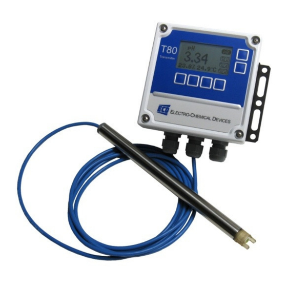
T80 Universal Transmitter
Model T80 Part Number Guide
S80 Intelligent Sensors
Electro-Chemical Devices
Advertisement
Quick Links
Download this manual
T80 Universal Transmitter
S80 Intelligent Sensors
Presented by:
January 2012
E
C
D
LECTRO-
HEMICAL
EVICES
Table of
Contents
Previous
Page
Next
Page
1
2
3
4
5
Advertisement
Table of Contents
Need help?
Do you have a question about the T80 and is the answer not in the manual?
Ask a question
Questions and answers
Related Manuals for ECD T80
Measuring Instruments ECD DO82 Instructional Manual
Hydra-ds nitrate analyzer (52 pages)
Transmitter ECD T90 Instruction Manual
Universal transmitter (75 pages)
Transmitter ECD S80 Manual
Universal transmitter/intelligent sensors (27 pages)
This manual is also suitable for:
S80
Table of Contents
Print
Rename the bookmark
Delete bookmark?
Delete from my manuals?
Login
Sign In
OR
Sign in with Facebook
Sign in with Google
Upload manual
Upload from disk
Upload from URL


Need help?
Do you have a question about the T80 and is the answer not in the manual?
Questions and answers