Table of Contents
Advertisement
Quick Links
Instruction Manual
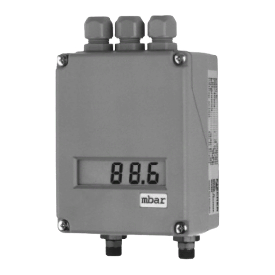
DE61 Differential Pressure Transmitter
Table of Contents
1.
Safety Instructions
2.
Intended Applications
3.
Product Description and Functions
4.
Installation
5.
Commissioning
6.
Maintenance
7.
Transport
8.
Service
9.
Accessories
10. Disposal
11. Specifications
12. Dimensions
13. Ordering Code
14. CE-Certificate
1.
Safety Instructions
1.1.
General
personnel responsible for the equipment must
read this thoroughly before attempting to install or
operate this equipment. A copy of this manual
must always be kept accessible at the place of
work for reference by concerned personnel.
Chapter 1 (sections 1.2 through 1.7) contains ge-
neral as well as specific safety instructions. Chap-
ters 2 through 10, covering topics ranging from
intended purpose of the equipment to its final dis-
posal, also include important points relating to
safety. Overlooking or ignoring any of these safety
points can endanger humans and animals, and
possibly cause damage to other equipment.
1.2.
Personnel Qualification
Personnel responsible for installation, operation,
maintenance and inspection of this product must
have the qualifications, training and experience
necessary to carry out such work on this type of
equipment.
This manual contains detailed
information about the product,
and instructions for its installati-
on, operation and maintenance.
Operators and other technical
1.3.
Risks of Disregarding Safety Instruc-
tions
Disregarding safety instructions, use of this pro-
duct for purposes for which it is not intended, and/
or operation of this product outside the limits spe-
cified for any of its technical parameters, can result
in harm to persons, the environment, or the plant
on which it is installed. Fischer Mess- und Regel-
technik GmbH will not be responsible for conse-
quences in such circumstances.
1.4.
Safety Instructions for Operators
Safety instructions for the proper use of this pro-
duct must be followed. This information must be
available at all times to by personnel responsible
for installation, operation, maintenance and in-
spection of this product. Adequate steps must be
taken to prevent the occurrence of hazardous con-
ditions that can be caused by electric energy and
the convertible energy of the process media. Such
conditions can, for example, be the result of impro-
per electrical or process connections. Detailed in-
formation is available in relevant published norms
(DIN EN, UVW in Germany; and equivalents in
other countries), industrial standards
such as DVWG, Ex-, GL-, VDE guide-
lines, as well as regulations of the local
authorities (e.g., EVUs in Germany).
Advertisement
Table of Contents

Related Manuals for FISCHER DE61


Summary of Contents for FISCHER DE61
- Page 1 Operators and other technical on which it is installed. Fischer Mess- und Regel- personnel responsible for the equipment must technik GmbH will not be responsible for conse- read this thoroughly before attempting to install or quences in such circumstances.
-
Page 2: Intended Applications
Any modifications to this product, if and as necessary, shock and vibration resistant and long-time stable. should be done only by Fischer Mess- und Regeltechnik The differential pressure acts on the sensor element and GmbH. -
Page 3: Adjustment Sequence
5.1. Pressure Connections • Connect and switch on power supply. The instruments pressure ports are marked by + and − • Measuring system depressurized: Output signal = 0 symbols. The pressure applications need to be installed resp. (4) mA. Correct offset using zero point potentio- according to the label. -
Page 4: Maintenance
Any defective devices or devices with missing parts However, to ensure reliable operation and maximize the should be retourned to Fischer Mess- und Regeltechnik operating life of the instrument, it is recommended that GmbH. For quick service contact our service department. -
Page 5: Specifications
11. Specifications General Measuring ranges 0...0.25 to 0...4.0 mbar (see 13. Ordering Code) Nominal pressure 0.6 bar Max. static pressure overpressure safe up to permitted nominal pressure Linearity 1% FS Hysteresis 0.1% FS Temperature drift 0.5% FS / 10K Perm. ambient temperature -10°...60°C Perm. - Page 6 12. Dimensions (all units in mm unless stated otherwise) Cable gland M16 x 1.5 Mounting holes ∅ 4.5 mm...
- Page 7 13. Ordering Code Differential Pressure Transmitter DE61 Measuring Range 0...0.25 mbar..............> 0...0.4 mbar..............> 0...0.6 mbar..............> 0...1.0 mbar..............> 0...1.6 mbar..............> 0...2.5 mbar..............> 0...4.0 mbar..............> other measuring ranges (please indicate in plain text) ..>...
- Page 8 Technische Änderungen vorbehalten • Subject to change without notice • Changements techniques sous réserve Fischer Mess- und Regeltechnik GmbH • Bielefelder Str. 37a • D-32107 Bad Salzuflen • Tel. +49 5222 9740 • Fax +49 5222 7170 eMail: info@fischermesstechnik.de • www.fischermesstechnik.de...
Need help?
Do you have a question about the DE61 and is the answer not in the manual?
Questions and answers