Table of Contents
Advertisement
Quick Links
Advertisement
Table of Contents

Related Manuals for Stealth Products mo-Vis Series


Summary of Contents for Stealth Products mo-Vis Series
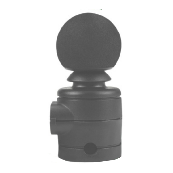
- Page 1 Multi Joystick mo-Vis Series Multifunctional Proportional Wheelchair Joystick...
-
Page 2: Table Of Contents
Table of Contents 1.0 Customer Satisfaction ......i 10.0 Q-Logic Setup......12-17 1.1 General............i 10.1 Q-Logic Prog. Setup....12-13 10.2 Q-Logic Prop. JS Setup.....14 2.0 Important Information...... ii 10.3 Center Deadband .......14 2.1 Important Information......ii 10.4 Tremor Suppression......15 2.2 Disposal ............ii 10.5 Assign Direction Function ....15 2.3 Supplier Reference ........ii 10.6 Joystick Calibration......16... -
Page 3: Customer Satisfaction
Customer Satisfaction Stealth Products is committed to 100% customer satisfaction. Your complete satisfaction is important. Please contact us with feedback or to suggest changes that may help us improve the quality and usability of our products. You may reach us at:... -
Page 4: Important Information
Important Information Important Information All persons responsible for fitting, adjustment, and daily use of the devices discussed in these instructions must be familiar with and understand all safety aspects of the devices mentioned. In order for our products to be used successfully, you must: ▪... -
Page 5: Introduction
The fitting, application, CAUTION and/or installation by a non-qualified individual could result in serious injury. Ordering Documentation Additional copies of this manual may be downloaded by accessing the Stealth Products website: https://stlpro.site/stealth-docs and searching "mo-Vis Multi Joystick"... -
Page 6: Warranty
Stealth Products, LLC. Any lack or alteration of serial number, where applicable, will automatically void this warranty. Stealth Products, LLC is liable for replacement parts only. Stealth Products, LLC is not liable for any incurred labor costs. -
Page 7: Warning Labels
Limited Liability Stealth Products, LLC accepts no liability for personal injury or damage to property that may arise from the failure of the user or other persons to follow the recommendations, warnings, and instructions in this manual. -
Page 8: Design And Function
Design and Function Intended Use The Multi Joystick: • is a joystick module which can be connected directly to the wheelchair electronics to control the wheelchair functions. • is a small proportional joystick, which requires significantly less power and movement compared to a normal joystick. -
Page 9: Parts And Accessories
Parts and Accessories Multi Joystick Package The following is included in the Multi Joystick package: Product Description: Part Number: Multi Joystick Set, with IDM-MULTI-9 integrated cabling and interface. Multi Joystick Accessories For mounting and further personalization, the following accessories are available: Package Part Unit Part Product Description... -
Page 10: Multi Joystick Prot. Covers
Stealth product. All of these items are compatible with the mo-Vis Power Chin Boom. Keep the protective cover in its place when not using a specific port. CAUTION Stealth Products can customize mounting hardware configurations in order to create the best possible fit for a client. -
Page 11: Functioning
Functioning Joystick Operation The movements of the joystick translate accordingly into the motion of the wheelchair or the navigation of its menu. The wheelchair is most commonly controlled by the joystick in the following manner: ▪ Direction: The joystick is pushed in the direction the wheelchair is intended to move, and the wheelchair moves in that direction. -
Page 12: Joystick Safety
Functioning Joystick Safety Do not use the Multi Joystick if any of the following conditions apply: ▪ The joystick handle is damaged, cracked, or missing. ▪ The joystick does not return to its default (center) position independently. ▪ The joystick does not move to and from its default (center) position smoothly. In order to change the joystick tip, gently pull on the tip until it lifts off the joystick's metal rod. -
Page 13: Connection Options
Functioning Connection Options The Multi Joystick can connect one or two switches to either the joystick or the interface. One connection is to power the on/off function and the other is to act as an input or user switch for the wheelchair. -
Page 14: Installation Instructions
Installation Instructions Preparations Only a qualified service technician should install the Multi Joystick and its accessories. An incorrect installation of wheelchair electronics may cause damage to the WARNING hardware and/or injury to the user. Any connection must always be secured with all the delivered screws. CAUTION Only use the screws provided with the device. -
Page 15: Installation Plan
Installa�on Instruc�ons Installation Plan Set up an installation plan before beginning the installation. This plan should take into account: ▪ where the Multi Joystick will be placed; ▪ how the Multi Joystick will be operated (i.e. by hand, chin or attendant); and, ▪... -
Page 16: Joystick Installation
The following instructions are for mounting to the Power Chin Boom. Please refer to the installation section of the manual for your specific mounting system to learn how to install the Micro Joystick on other Stealth products. All wheelchair electronics must be switched off during installation. -
Page 17: Defining Position (Parameters)
Installation Instructions Ensure all cabling is mounted in such a way WARNING as to avoid excessive wear and tear. • If required, place a power on/off (pwr) and/or mode (in) switch, secure their cabling and insert their connections. • You can use the connections on the Interface Unit. •... -
Page 18: Connection Cable Installation
Installation Instructions Connection Cable Installation Ensure the pins in the 9-pin connector are straight and none are bent. Insert the connector into the jack on the chair and secure with the screws on the connector. To disconnect the 9-pin connector, unscrew the retaining screws and pull gently to separate the connector from the jack. -
Page 19: Q-Logic Setup
Q-Logic™ Setup 10.0 Q-Logic Programmer Setup 10.1 Bookmark Buttons Select Options in the main menu. Button actions are displayed on-screen above Navigation corresponding buttons. In other menus, hold button to Arrows navigate the main bookmark settings, and menu. Up & Down to press button to quickly go navigate the menus, to a bookmark. - Page 20 Q-Logic™ Setup 10.0 For new chairs that have never been programmed, a power cycle NOTICE will need to be completed after the joystick has been calibrated and before the joystick throw can be adjusted. Disengage the brake then plug in the Q-Logic Handheld Programmer (Previous Page) to the Q-Logic ED (Enhanced Display) or the standalone joystick if SCIM (Specialty Control Input Module shown below) is in use.
-
Page 21: Q-Logic Prop. Js Setup
Q-Logic™ Setup 10.0 Q-Logic Proportional Joystick Setup 10.2 Plug in the Q-Logic Handheld Programmer (Previous Page) to the Q-Logic ED (Enhanced Display) or the standalone joystick if SCIM (Specialty Control Input Module shown below) is in use. On the Q-Logic Programmer, navigate to Program Adjustments Enhanced Display Proportional Input . -
Page 22: Tremor Suppression
Q-Logic™ Setup 10.0 Tremor Suppression 10.4 The Tremor Suppression parameter sets a neutral range that suppresses possible tremors (trembling of hand or drive surface conditions) on the joystick. Setting from 0% to 100%. ▪ Follow Steps 1 & 2 from Section 10.2 ▪... -
Page 23: Joystick Calibration
Q-Logic™ Setup 10.0 Joystick Calibration 10.6 Calibrating your joystick will set the range of motion for the axes or re-center it to improve operation. Calibration MUST be performed for the joystick. This is a new safety feature CAUTION update included in Q-Logic Programmers. ▪... -
Page 24: R-Net Setup
R-Net Setup 11.0 R-Net Omni Setup 11.1 Power Button Settings Button Sounder LCD Screen Profile Button Mode Button - Button + Button Navigation Buttons Display / Input Section Connector R-Net Programming Dongle... -
Page 25: R-Net Setup
R-Net™ Setup 11.0 R-net Setup 11.2 For mo-Vis R-net joysticks to operate properly, some R-net parameters need to be set. information about R-net parameters, please refer to the Curtiss-Wright manual SK77981-14 | R-net Technical Manual | Chapter 3 -- Programming. - R-net Profile Management >... -
Page 26: Joystick Calibration
R-Net™ Setup 11.0 In the Profiled menu, configure a profile to use the port for the Multi Joystick. Power off the chair, remove the R-Net Programming Dongle, reconnect the Omni display and power on the chair. • The chair should now be programmed to recognize the Multi Joystick. Be sure to re-engage the motors before operation. -
Page 27: Throw
R-Net™ Setup 11.0 With the navigation buttons, navigate to Controls Joystick. Here you can fine tune joystick performance and functionalities, such as: ▪ Active Throw Details ▪ Active Orientation and Orientation Details ▪ Deadband Throw 11.6 The Throw is the place where the joystick is stopped in a particular direction. Throw Distance is the maximum distance/angle the shaft can be moved in a particular direction. -
Page 28: Axis Orientation
R-Net™ Setup 11.0 Axis Orientation 11.7 Axis Orientation allows you to switch the axis behavior. For example, the X-axis (Forward/Reverse) can be switched, making the Forward direction Reverse, and vice versa. Active Orientation • Follow the first three steps in Section 11.4. •... -
Page 29: Center Deadband
R-Net™ Setup 11.0 Center Deadband 11.8 The Center Deadband parameter defines how far the joystick must be moved from neutral position to engage the motors of power chair. The value corresponds to the diameter of a circle around the joystick center position. No drive or menu instructions will be executed unless the joystick is moved out of this circle. -
Page 30: Software Configuration
Software Download 12.2 The mo-Vis Configurator Software can be downloaded on Stealth Products' website (www.stealthproducts.com). For details on how to install and use the software, the user is advised to consult the software manual, included alongside the download. -
Page 31: Parameter Settings
Configuration Software 12.0 mo-Vis Configurator Parameter Settings 12.3 The mo-Vis Configurator Software allows users to change the parameters of the Multi Joystick, depending on the level of profile assigned. MOUNTING SETTINGS (DEALER LEVEL) Setting Description Parameters Default: 0° Changes the joystick axis in Min.: 0°... - Page 32 Configuration Software 12.0 COMPENSATION MODE Setting Description Parameters Always deactivated Defines the activation Compensation of the compensation Manual (De)activated manually by the user Mode algorithm Always activated (Note: Front wheel-driven wheelchairs are less affected by this factor than rear wheel-driven chairs.) Setting Description Parameters...
-
Page 33: Testing
Testing 13.0 COMPENSATION FACTOR Setting Description Parameters Almost no Very Weak deceleration Lowers forward/backward (Y) Decelerates less than driving speed on rough terrain. Weak Normal Compensation (Wheelchair type Factor Normal Default Setting and weight impact the compensation factor.) Decelerates more Strong than Normal (Note: If the joystick is mounted in a location susceptible to bumps and shocks, such as a wheelchair arm,... - Page 34 Testing 13.0 VISUAL TEST Check to ensure: ▪ the joystick is not bent or damaged; ▪ none of the joystick's housing, cabling, or connectors are damaged; and, ▪ the joystick returns to its default (center) position upon release. The device should always be tested without any person sitting in the WARNING wheelchair after every alteration of the physical installation or adjustment of the parameters...
-
Page 35: Error Codes And Fault Logs
Error Codes and Fault Logs 14.0 STOPPING TEST Drive the wheelchair forward at full speed, then use the power on/off switch to shut the wheelchair down. ▪ The wheelchair should not stop abruptly, but should gradually slow to a stop. Error Codes 14.1 When a fault occurs, the LED of the Micro Joystick will start to flash. - Page 36 Error Codes and Fault Logs 14.0 Fault: Reason for Fault: Required Action: CPU Error: RAM CPU Error: FLASH CPU consistency check failed Replace PCB. CPU Error: EEPROM Run Error: Scheduler - Update software. Code Error: Framework Firmware consistency check failed - Replace PCB.
- Page 37 Error Codes and Fault Logs 14.0 Fault: Reason for Fault: Required Action: A fault occurred during Field Test Failed Field test failed (Calibration). Field Testing (calibration). One or More Test flags Not Redo test(s) Test Flag Check Set. and/or Replace PCB. - Check R-net Cable, ADC Conversion error Replace PCB Interface.
-
Page 38: Technical Data
Technical Data 15.0 Technical Data 15.1 JOYSTICK CONNECTORS ▪ 1/8" (3.5mm) mono jack input (on/off) ▪ 1/8" (3.5mm) mono jack input (mode) ▪ Mini USB ▪ SUB D9 Connector JOYSTICK DIMENSIONS ▪ Joystick: 2.64 in. x 1.31 in. (67mm x 33mm) - [Height x Depth] ▪... -
Page 39: First Time Use
First Time Use 16.0 Dealer Assistance 16.1 During first time use by the client, it is advised that the dealer or service technician not only install the device, but also explains the configuration and different possibilities to the customer (i.e., the user and/or the attendant). -
Page 40: Maintenance
Maintenance 17.0 Maintenance 17.1 The Multi Joystick is designed to be maintenance-free. Under the circumstances of regular use, the joystick, interface, and assembly parts do not require additional maintenance. Always check all mounting hardware, making sure each fastener CAUTION is properly tightened before using the Multi Joystick. SAFETY Replace or repair parts as needed. -
Page 41: Monthly Check
Maintenance 17.0 Monthly Check 17.3 Monthly, or as needed, check to ensure: ▪ all bolts and screws are still tightened firmly; ▪ The wiring has sustained no damage; and, ▪ none of the joystick unit's parts have suffered excessive wear or tear. A yearly check of the wheelchair and its operating systems by a qualified technician is recommended. -
Page 42: Notes
Notes 18.0... - Page 43 Software Configuration...
- Page 44 © 2021, Stealth Products, LLC Warranty Information Home Page Online User Manual Stealth Products, LLC · info@stealthproducts.com · www.stealthproducts.com (800) 965-9229 | (512) 715-9995 | 104 John Kelly Drive, Burnet, TX 78611 P120D702 mo-Vis Multi-9 Owners Manual.afpub Sep 23, 2022...
Need help?
Do you have a question about the mo-Vis Series and is the answer not in the manual?
Questions and answers