
Related Manuals for Stealth Products ADI HA-42


Summary of Contents for Stealth Products ADI HA-42
- Page 1 Disc Brake Systems Disc Brake Systems Owner’s Manual - Maintenance Guide ADI HA-42 Disc Brake System...
-
Page 2: Table Of Contents
Table of Contents Customer Satisfaction .................... i Important Information..................ii-iii Warranty ..........................ii Supplier Reference......................ii Warning Labels........................iii Limited Liability ......................... iii Testing........................... iii Design and Function ....................1 Intended Use........................1 Features..........................1 Parts and Accessories ..................2-6 Disc Brake Package Components................2 HA-42 Disc Brake Kit...................... -
Page 3: Customer Satisfaction
For further assistance, or more advanced applications, please contact your supplier or Stealth Products at (512) 715-9995 or toll free at (800) 965-9229. Always keep the operating instructions in a safe place so they may be referenced as necessary. -
Page 4: Important Information
In the event of a product failure covered by our warranty, please follow the procedures outlined below: Call Stealth Products at (512) 715-9995 or toll free at (800) 965-9229. Request a Return Authorization (RA) form from the Returns Department and follow the documentation instructions. -
Page 5: Warning Labels
Stealth Products does not hold responsibility for final integration of final assembly of product to end user. Stealth Products is not liable for user death or injury. Testing Initial setup and driving should be done in an open area free of obstacles until the user is fully capable of driving safely. -
Page 6: Design And Function
Design and Func�on Intended Use ADI's disc brake systems are intended to be used with manual wheelchairs. They are designed to attach to the camber tube region of the wheelchair and slow/stop the wheelchair upon brake lever activation. Disc brakes offer a positive lock independent of the tire pressure/wear, reduce upper body fatigue, augment user control, and afford users of all physical abilities near-effortless braking ability. -
Page 7: Parts And Accessories
Parts and Accessories Disc Brake Package Components ADI's Disc Brake Packages are comprised of two parts: • A disc brake kit (HA-42); and, • a brake actuator lever (Variable, Para, or A�endant). HA-42 Disc Brake Kit Below is a basic diagram of components included with brake kits: Part Qty. -
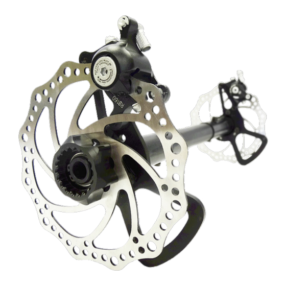
Page 8: Basic Caliper Components
Parts and Accessories BASIC CALIPER COMPONENTS Part Description Qty. Caliper Compresses Brake Pad Caliper Input Ferrule Houses Brake Cable Moving Arm (Caliper) Engages Brake Cable Adjustment Bolts Adjust Caliper Positioning... -
Page 9: Variable Lever Assembly
Parts and Accessories VARIABLE LEVER ASSEMBLY Part Description Qty. Lever Adjustment Bar Attaches lever assembly to frame clamp Cable Block Seats and secures brake cables Cable Housing Clamp Seats and secures cable housing Cable Block Set Screw (10-32) Tighten to secure brake cables Cable Housing Clamp Screws (10-32) Tighten to secure cable housing VARIABLE LEVER BRAKE CABLES AND HOUSING... -
Page 10: Para Lever Assembly
Parts and Accessories PARA LEVER ASSEMBLY Part Description Qty. Lever Engages Brake System Lever Adapter Insert Enables Cane Compatibility PARA LEVER BRAKE CABLES AND HOUSING Part Description Qty. Brake Cables Connect disc brake calipers to lever system Brake Cable Housing Houses and protects brake cables MTB Brads Cap and help seat brake cables... -
Page 11: Attendant Lever Assembly
Parts and Accessories ATTENDANT LEVER ASSEMBLY Part Description Qty. Lever Engages Brake System ATTENDANT LEVER BRAKE CABLES AND HOUSING Part Description Qty. Brake Cables Connect disc brake calipers to lever system Brake Cable Housing Houses and protects brake cables MTB Brads Cap and help seat brake cables Metal End Caps (Cables) Crimped to prevent cable wear/unraveling... -
Page 12: Installation Instructions
Installa�on Instruc�ons Preparations Only a qualified service technician may install ADI disc brake systems. An incorrect installation of the brake system or its accessories may cause damage WARNING to the hardware and/or injury to the user. Tools Use the proper tools to install and adjust the ADI disc brake system to the desired position for the user. - Page 13 Installa�on Instruc�ons Step 1: Use a tape measure to take the original measurements of the wheelchair's delivered configuration. Step 2: Remove the rear wheels and loosen the axle receivers using a 1 1/8" wrench or socket wrench. • To ensure the proper location of installation,...
- Page 14 Installa�on Instruc�ons Step 3: Working one side at a time, place each 3/4"-16 threaded axle insert provided through each .300" spacer, then through the corresponding caliper bracket. Install the arranged parts onto the slotted axle plates using the OEM positioning washers and 3/4"-16 slim lock nuts.
- Page 15 Installa�on Instruc�ons Step 6: Tighten the OEM 3/4"-16 slim lock nut using a 1 1/16" wrench or socket wrench. Step 7: Place each caliper over its corresponding rotor disc and simultaneously slide both parts onto the slotted axle plate and the caliper's "U"-shaped bracket.
- Page 16 Installa�on Instruc�ons Step 8: Secure the rotor assemblies with the retaining rings provided. Retaining Ring Step 9: Attach the calipers to their "u"-shaped brackets by replacing and tightening the removed adjustment bolts. Center the calipers on the rotor discs and tighten the adjustment bots with a 5mm hex key, taking care not to over-tighten.
-
Page 17: Brake Lever Installation Instructions
Installa�on Instruc�ons Lever Kit Installation Instructions Each disc brake package will include a brake lever kit specified when the brake package was ordered. These instructions cover all three styles of brake lever. Instructions specific to one or more styles, but not all, will be marked with the names of the styles they apply to. - Page 18 Installa�on Instruc�ons • It is recommended that after the lever is mounted, it should not extend past the chair's frame when engaged fully forward. 3. [VARIABLE & PARA] Insert the lever adjustment bar into the existing frame clamp. Adjust to proper position and use a hex key to secure. 4.
- Page 19 Installa�on Instruc�ons • To gauge the necessary length of the housing, gently crimp a metal end cap to one end of the housing and insert this crimped end into the cable input ferrule on the caliper. (Do this with both the same-side and opposite-side calipers, ensuring equal length on both sides.) •...
- Page 20 Installa�on Instruc�ons [PARA & ATTENDANT] Run one end of the cable through the lower hole in the lever, pulling the cable until the MTB brad fits securely in the recess. Feed the cable through cable housing, checking for smooth operation. 3.
-
Page 21: Caliper Adjustments
Installa�on Instruc�ons Caliper Adjustments This section details caliper components, and lists the tools and steps required to adjust them. CALIPER COMPONENTS AND REQUIRED TOOLS Outer Pad Adjustment Cable Locking Clamp (5mm Hex Key) (4mm Hex Key) Inner Pad Adjustment Outer Pad Set Screw (3mm Hex Key) (2.5mm Hex Key) Attachment Bolts... - Page 22 Installa�on Instruc�ons Calipers have four points of adjustment: ▪ Inner Pad Adjustor ▪ Outer Pad Adjustor ▪ A�achment Bolts ▪ Cable Input Ferrule Step 1: Begin by checking that the movable arms on both calipers are at a full open position when the brake is in the neutral position with little to no slack in the cable system.
-
Page 23: First Time Use
First Time Use Dealer Assistance During first time use by the client, it is advised that the dealer or service technician assists in assembly and explains the configuration of user positioning to the customer (the user and/or the attendant). If needed, the dealer can make final adjustments. -
Page 24: Cleaning And Maintenance
Cleaning and Maintenance Cleaning Use a soft, damp cloth to clean the hardware and its components. Ensure that all cleaners are approved for finished steel and aluminum. Disinfecting Gently wipe the hardware with a soft cloth dampened with a household disinfectant. -
Page 25: Notes
Notes... - Page 26 Notes...
- Page 27 Notes...
- Page 28 © 2021, Stealth Products, LLC Warranty Information Home Page Online User Manual Stealth Products, LLC · info@stealthproducts.com · www.stealthproducts.com (800) 965-9229 | (512) 715-9995 | 104 John Kelly Drive, Burnet, TX 78611 P147D594R2 HA-42 Owner's Manual.afpub May 13, 2021...
Need help?
Do you have a question about the ADI HA-42 and is the answer not in the manual?
Questions and answers