
Related Manuals for YOKOGAWA DLM5034


Summary of Contents for YOKOGAWA DLM5034
- Page 1 User’s Manual DLM5034, DLM5038, DLM5054, DLM5058 Mixed Signal Oscilloscope Getting Started Guide IM DLM5058-03EN 4th Edition...
- Page 2 Contact Us If you want to resolve a technical support issue or need to contact YOKOGAWA, please fill out the inquiry form on our website. https://tmi.yokogawa.com/contact/ PIM 103-06E...
- Page 3 Thank you for purchasing the DLM5034, DLM5038, DLM5054, or DLM5058 Series Mixed Signal Oscilloscope. This getting started guide primarily explains the handling precautions and basic operations of this instrument. To ensure correct use, please read this manual thoroughly before operation.
-
Page 4: Manuals
The following manuals, including this one, are provided as manuals for this instrument. Please read all manuals. Manual Title Manual No. Description DLM5034, DLM5038, DLM5054, DLM5058 IM DLM5058-01EN The included CD contains PDF data. Mixed Signal Oscilloscope This manual explains all the instrument’s Features Guide features other than the communication interface features. -
Page 5: Checking The Contents Of The Package
YOKOGAWA dealer. DLM5034, DLM5038, DLM5054, or DLM5058 Check that the product that you received is what you ordered by referring to the model name and suffix code given on the name plate on the left side panel. - Page 6 Checking the Contents of the Package Model Suffix Code Specifications Options /L32 Logic 16-bit expansion (32 bits total) Built-in printer /M1S Memory expansion 25 M /125 M /250 M points (4ch model only) /M2S Memory expansion 50 M /250 M /500 M points (4ch model only) Memory expansion 25 M...
- Page 7 Checking the Contents of the Package Standard Accessories The standard accessories below are supplied with the instrument. Check that all contents are present and undamaged. Item Model or Part No. Quantity Specifications and Notes Power cord See the figure Included or not included depending on the below.
- Page 8 The English folder in the manual CD contains the PDF files shown below. The CD also contains Japanese manuals. File Name Manual Title Manual No. Features Guide & Users Manual.pdf DLM5034, DLM5038, DLM5054, DLM5058 IM DLM5058-01EN Mixed Signal Oscilloscope Features Guide DLM5034, DLM5038, DLM5054, DLM5058...
- Page 9 When using several accessories together, use them within the specification range of the accessory with the lowest rating. • If you use accessories other than those below, YOKOGAWA assumes no responsibility or liability for the specifications of this instrument or any damage caused by the use of this instrument.
- Page 10 Min. Item General Specifications Manual No. Part No. Q’ty PBDH1000 differential probe DC to 1 GHz bandwidth, with YOKOGAWA probe 701924 maximum differential input voltage ±25 V IM 701924-01E interface (DC+AC peak) PBDH0500 differential probe DC to 500 MHz bandwidth,...
- Page 11 Checking the Contents of the Package Model or Min. Item General Specifications Manual No. Part No. Q’ty Number of outputs: 4, output voltage: Probe power supply 701934 IM 701934-01E ±(12 ± 0.5) V Output voltage (square wave): approx. 0 to 5 V, Deskew signal source 701936 output current (square wave):...
-
Page 12: Conventions Used In This Manual
Conventions Used in This Manual Prefixes k and K Prefixes k and K used before units are distinguished as follows: Denotes 1000. Example: 100 kS/s (sample rate) Denotes 1024. Example: 720 KB (file size) Displayed Characters Bold characters in procedural explanations are used to indicate panel keys and soft keys that are used in the procedure and menu items that appear on the screen. -
Page 13: Safety Precautions
The general safety precautions described herein must be observed during all phases of operation. If the instrument is used in a manner not specified in this manual, the protection provided by the instrument may be impaired. YOKOGAWA assumes no liability for the customer’s failure to comply with these requirements. - Page 14 Do Not Remove the Covers or Disassemble or Alter the Instrument Only qualified YOKOGAWA personnel may remove the covers and disassemble or alter the instrument. The inside of the instrument is dangerous because parts of it have high voltages.
- Page 15 Doing so may cause loss of hearing or speaker damage due to the large sounds that may be produced. Accessories Use the accessories specified in this manual. Moreover, use the accessories of this product only with Yokogawa products that specify them as accessories. Do not use faulty accessories. CAUTION Operating Environment Limitations This product is classified as Class A (for use in industrial environments).
- Page 16 Ne pas retirer le capot, ni démonter ou modifier l’instrument Seul le personnel YOKOGAWA qualifié est habilité à retirer le capot et à démonter ou modifier l’instrument. Certains composants à l’intérieur de l’instrument sont à haute tension et par conséquent, représentent un danger.
- Page 17 élevé des sons produits. Accessoires Utiliser les accessoires spécifiés dans ce manuel. En outre, utiliser les accessoires de ce produit uniquement avec des produits Yokogawa pour lesquels ils sont spécifiés comme accessoires. Ne pas utiliser d’accessoires défectueux.
-
Page 18: Regulations And Sales In Each Country Or Region
Authorized Representative in the EEA Yokogawa Europe B.V. is the authorized representative of Yokogawa Test & Measurement Corporation for this product in the EEA. To contact Yokogawa Europe B. V., see the separate list of worldwide contacts, PIM 113-01Z2. 關於在台灣銷售... -
Page 19: Table Of Contents
Contents Manuals ............................ii Checking the Contents of the Package.................... iii Conventions Used in This Manual ....................x Safety Precautions ........................... xi Regulations and Sales in Each Country or Region ................ xvi Chapter 1 Component Names and Functions Front, Right, Left, Top, and Rear Panels ................ 1-1 Keys and Knobs ...................... - Page 20 Contents Chapter 5 Troubleshooting, Maintenance, and Inspection If a Problem Occurs ....................... 5-1 Messages and Corrective Actions .................. 5-2 Carrying Out Self-Tests ....................5-9 Viewing System Information (Overview) ..............5-12 Adding Options to the Instrument ................. 5-13 Formatting the Internal Storage ................... 5-15 Recommended Part Replacement ................
-
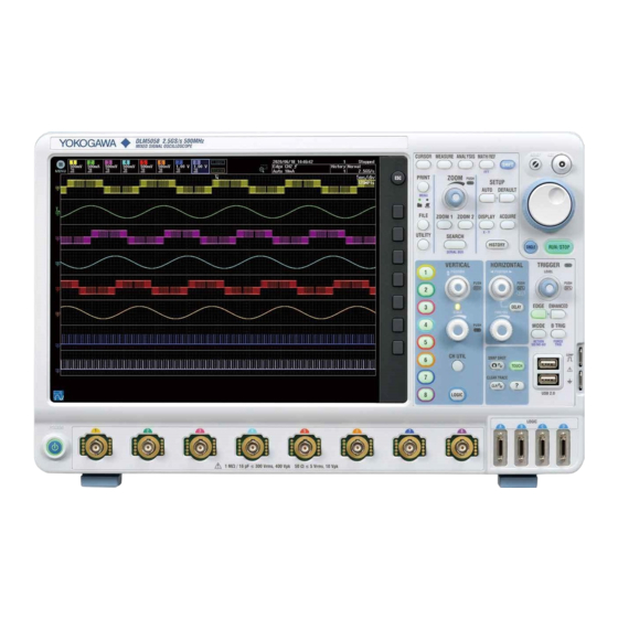
Page 21: Chapter 1 Component Names And Functions
32-bit logic signals. → sec. 2.6 Power switch → sec. 2.3 * LOGIC C and D (logic signal input ports) are equipped on models with the /L32 option. DLM5034 and DLM5054 Signal input terminals - probe interface terminals (CH1 to CH4) Connect probes to these terminals to observe analog signals. - Page 22 1.1 Front, Right, Left, Top, and Rear Panels Right Side Panel Inlet holes Probe power terminal (optional) Use these terminals to supply power to a YOKOGAWA FET probe or current probe. → sec. 2.4 Main power switch → sec. 2.3 Power connector →...
- Page 23 1.1 Front, Right, Left, Top, and Rear Panels Top Panel Handle Inlet holes Built-in printer (option) Prints the display. Rear Panel GO/NO-GO output port This connector transmits GO/NO-GO result signals. → sec. 4.4 External trigger USB port for PCs input terminal Use to connect to a PC that has a USB port.
-
Page 24: Keys And Knobs
Keys and Knobs Vertical Axis/Channel CH1 to CH8 keys and LOGIC key When you press any of these keys, a menu appears for turning analog signal input channels on and off and for setting the coupling, probe type, offset voltage, bandwidth limit, linear scaling, and waveform labels. - Page 25 1.2 Keys and Knobs Horizontal Axis ◄POSITION► Knob Use this knob to move the center position (trigger position) when you change the time range. When you move the trigger position, the ratio of the displayed data before the trigger point (the pre-trigger section) to the data after the trigger point (the post-trigger point) changes.
- Page 26 1.2 Keys and Knobs Trigger EDGE Key Press this key to display a menu for setting the edge trigger. When you press this key, the edge trigger is selected, and the key illuminates. ENHANCED Key Press this key to display a menu for setting the enhanced trigger. When you press this key, the enhanced trigger is selected, and the key illuminates.
- Page 27 1.2 Keys and Knobs Waveform Acquisition and Display SETUP Key • AUTO Key Press this key to automatically set values that correspond to the input signal. Undo appears in the menu, and you can undo the settings made with this key. •...
- Page 28 1.2 Keys and Knobs Zoom, Search, and Serial Bus ZOOM1 and ZOOM2 Keys Press either key to display a waveform zoom display menu. When a waveform zoom display is on, the corresponding key illuminates. If ZOOM1 and ZOOM2 are both on, the ZOOM knob controls the magnification of the zoom waveform whose corresponding key is illuminated brightly.
- Page 29 1.2 Keys and Knobs Screen Capture Printing and Data Storage PRINT Key Press this key to print or save screen capture data. SHIFT+PRINT (MENU) Key Press these keys to display a menu for printing screen capture data with the built-in printer, a USB printer, or a network printer or a menu for saving screen capture data to a storage device.
- Page 30 1.2 Keys and Knobs SHIFT key Press this key once to illuminate it and access the features that are written in purple below each key. Press the key again to clear that state. Jog Shuttle When configuring various settings, use the jog shuttle to set values, move cursors, and select items.
- Page 31 1.2 Keys and Knobs Notes about the Operation of Knobs with Push Switches The following knobs have push switches: POSITION (vertical and horizontal), SCALE, LEVEL, and ZOOM. Push the knobs straight. If you push a knob at an angle, it may not operate properly. If this happens, push the knob straight one more time.
-
Page 32: Screens
Screens Normal Analog Signal Waveform Screen Top menu icon Set the zoom range. Displays the top menu Set the range and zoom the waveform → sec. 3.2 → sec. 3.2 Number of waveform acquisitions See the next table. Trigger position Channel information Waveform acquisition state Trigger point... - Page 33 1.3 Screens Waveform Acquisition States Stopped Waveform acquisition is stopped. Running Waveform acquisition is taking place. Preview This state indication appears when waveform acquisition is stopped and a waveform acquisition condition such as the vertical scale (SCALE), time-axis scale (TIME/DIV), or trigger has been changed.
- Page 34 1.3 Screens Screen Displaying Zoom Waveforms Zoom position of X-direction zoom X-direction zoom Zoom position of zoom waveform Z1 range of Z1 range of Z2 zoom waveform Z2 Normal waveform Time/div Normal waveform display record length Main window Z1 Time/div Z1 display record length Z2 Time/div...
- Page 35 1.3 Screens Screen Displaying Analysis Results Waveform histogram Waveform display area Measured waveform parameter values (statistics) Cursor-measurement Area for values displaying Statistics the result of histogram statistical processing If the setup menu is not displayed, measured waveform parameter values or cursor measurement values can be displayed in the area at the bottom of the screen (the area outside of the waveform and measured value display areas).
-
Page 36: Chapter 2 Measurement Preparation
Unplug If Abnormal Behavior Occurs If you notice smoke or unusual odors coming from the instrument, immediately turn off the power and unplug the power cord. Then, contact your nearest YOKOGAWA dealer. Do Not Damage the Power Cord Nothing should be placed on top of the power cord, and it should be kept away from any heat sources. - Page 37 2.1 Handling Precautions Connecting a PC to the Instrument Before connecting a PC to the USB port for PCs, ground the PC to the same electrical potential as the instrument. When Carrying the Instrument Remove the power cord and connecting cables. When carrying the instrument, either hold the handle or hold the instrument with both hands as shown in the figure below.
-
Page 38: Appropriate Locations For Using The Instrument
Appropriate Locations for Using the Instrument WARNING • Do not install the instrument outdoors or in locations subject to rain or water. • Install the instrument so that you can immediately remove the power cord if an abnormal or dangerous condition occurs. CAUTION If you block the inlet or outlet holes on the instrument, it will become hot and may break down. - Page 39 2.2 Appropriate Locations for Using the Instrument Well-Ventilated Location Inlet holes are located on the top panel and the left and right side panels of the instrument. In addition, there are outlet holes for the cooling fan on the rear panel. To prevent internal overheating, allow for enough space around the instrument (see the figure below) and do not block the inlet and outlet holes.
- Page 40 2.2 Appropriate Locations for Using the Instrument Do not install the instrument in the following places. • Outdoors • In direct sunlight or near heat sources • Where the instrument is exposed to water or other liquids • Where an excessive amount of soot, steam, dust, or corrosive gas is present •...
- Page 41 2.2 Appropriate Locations for Using the Instrument French AVERTISSEMENT • Lorsque vous manipulez les pieds escamotables, veillez à ne pas vous blesser la main. • Lorsque vous rangez les pieds ou le support escamotable, veillez à ne pas vous coincer la main entre l’instrument et les pieds ou le support.
-
Page 42: Connecting The Power Supply And Turning The Power Switch On And Off
Connecting the Power Supply and Turning the Power Switch On and Off Before Connecting the Power Supply Make sure to follow the warnings below when connecting the power supply. Failure to do so may cause electric shock or damage to the instrument. WARNING •... - Page 43 2.3 Connecting the Power Supply and Turning the Power Switch On and Off Connecting the Power Cord Check that the main power switch on the right side panel of the instrument is turned off. Connect the power cord plug to the power connector on the right side panel. Connect the other end of the cord to an outlet that meets the following conditions.
- Page 44 • It may take a few seconds for the startup screen to appear. • If the instrument still does not start properly even when you turn on the power switch while holding down the RESET key, contact your nearest YOKOGAWA dealer for repairs. Turning Off the Power Switch...
- Page 45 2.3 Connecting the Power Supply and Turning the Power Switch On and Off French ATTENTION Mettre brutalement l’instrument hors tension ou débrancher le cordon d’alimentation pendant l’enregistrement de données ou le fonctionnement de l’imprimante interne peut corrompre le support d’enregistrement des données ou endommager l’imprimante intégrée. Les données en cours d’enregistrement pourront également être perdues.
-
Page 46: Connecting Probes
Connecting Probes WARNING • When connecting a device under measurement to the instrument, be sure to turn off the device. It is extremely dangerous to connect or disconnect a measuring lead while the device under measurement is on. • Do not apply input voltage exceeding the maximum input voltage, withstand voltage, or allowable surge voltage. - Page 47 2.4 Connecting Probes French AVERTISSEMENT • Lors de la connexion à l’instrument d’un appareil faisant l’objet de la mesure, éteindre impérativement l’appareil. Il est extrêmement dangereux de brancher un câble de mesure lorsque l’appareil à mesurer est sous tension. • Ne pas dépasser les valeurs maximales de tension d’entrée, de tension de maintien ou de surtension admissible.
- Page 48 2.4 Connecting Probes • Si vous modifiez le paramètre de couplage d’entrée alors que l’acquisition de forme d’onde est arrêtée, le couplage d’entrée sur l’instrument est en réalité modifié lorsque la prochaine acquisition de forme d’onde est exécutée. Faites attention à la tension d’entrée maximale. •...
- Page 49 2.4 Connecting Probes About Probes Specifications, after probe phase compensation, of the probe (model 701937) that is supplied as a standard accessory For details, see the manual that came with the probe. Item Specifications Probe length Approx. 1.3 m Input resistance 10 MΩ...
- Page 50 Connecting an FET Probe, Current Probe, or Differential Probe If you are using a YOKOGAWA FET probe, current probe, or differential probe, use one of the probe power terminals (option) on the instrument’s right side panel for the power supply.* For details on the connection procedure, see the manual that came with the product that you want to use.
- Page 51 2.4 Connecting Probes Handling Precautions for the Probe Interface Terminals and Probe Power Terminals If you are connecting an FET probe, current probe, or differential probe to one of the probe power terminals (option) on the right side panel, be sure that the total current of the eight probe power terminals and the eight probe interface terminals (±12 V each) on 8 channel models or that of the four probe power terminals and the four probe interface terminals (±12 V each) on 4 channel models does not exceed 2.0 A.
-
Page 52: Correcting A Probe Phase
Correcting a Probe Phase Before using a probe to make measurements, be sure to correct the probe phase. CAUTION Do not apply external voltage to the signal output terminal for probe compensation adjustment. This may cause damage to the internal circuitry. French ATTENTION Ne pas appliquer de tension externe sur la borne de sortie de signal afin d'ajuster la... - Page 53 2.5 Correcting a Probe Phase Explanation Necessity of Probe Phase Correction The phase of each probe is already corrected so as to approximately match the input capacitance of the oscilloscope that the probe is intended to be used with. However, the input resistance and input capacitance each of the input channels of each individual oscilloscope vary.
-
Page 54: Connecting Logic Probes
Connecting Logic Probes WARNING • When connecting a device under measurement to the instrument, be sure to turn off the device. • Do not apply voltage exceeding the maximum input voltage. • To avoid electric shock, be sure to ground the instrument. Furthermore, connect the ground of the probes or input connectors to the ground potential of the device under measurement. - Page 55 2.6 Connecting Logic Probes ATTENTION • La tension d’entrée maximum pour la sonde logique 701989 est ± 40 V (CC + CA crête) ou 28 Vrms, et la tension d’entrée maximum pour la sonde logique 701988 est ± 42 V (CC + CA crête) ou 29 Vrms.
- Page 56 2.6 Connecting Logic Probes Logic Input Specifications When Used with the Instrument The specifications of the 701988 and 701989 are as follows. For details, see page 6-3. Item When using the 701988 When using the 701989 Maximum toggle frequency 100 MHz 250 MHz Number of input bits Maximum input voltage...
-
Page 57: Affixing The Panel Sheet
Affixing the Panel Sheet Affix the supplied panel sheet to the instrument as necessary. The panel sheet that comes with the instrument is determined by language suffix code. Procedure Affixing the Panel Sheet You can affix the panel sheet over the panel sheet that is affixed to the instrument when it is shipped from the factory. -
Page 58: Loading Roll Paper Into The Built-In Printer (Optional)
This section explains how to load roll paper into the optional built-in printer. Printer Roll Paper Use a YOKOGAWA roll paper. Do not use any other paper. When using the printer for the first time, use the roll paper supplied with the instrument. When you need extra roll paper, please contact your nearest YOKOGAWA dealer. - Page 59 2.8 Loading Roll Paper Into the Built-In Printer (Optional) Loading the Roll Paper CAUTION • Do not touch the print head. If you do, you may burn yourself. • Do not touch the roll paper cutter section at the end of the printer cover. Doing so may cause injury.
-
Page 60: Chapter 3 Common Operations
Chapter 3 Common Operations Key and Jog Shuttle Operations key Operations How to Use Setup Menus That Appear When Keys Are Pressed The operation after you press a key varies depending on the setup menu type. FFT menu CURSOR menu MODE menu Index Jog shuttle setting menu... - Page 61 3.1 Key and Jog Shuttle Operations ESC Key Operation • If you press ESC when a setup menu or available options are displayed, the screen returns to the menu level above the current one. • If you press ESC when the highest level menu is shown, the display changes as follows. Operation of When measured values are displayed When measured values are not displayed...
- Page 62 3.1 Key and Jog Shuttle Operations How to Enter Values in Setup Dialog Boxes Display the appropriate setup dialog box. Turn the jog shuttle, or tilt the SET key ( ) up, down, left, or right to move the cursor to the appropriate item.
-
Page 63: Touch Panel Operations
Touch Panel Operations Touch Panel Operations The basic touch panel operations are described below. Tap refers to the act of touching the screen lightly and letting go quickly. Tapping is used on the instrument screen to select areas with a mark as well as items on setup menus and dialog boxes. - Page 64 3.2 Touch Panel Operations Top Menu Operation (same operation as the front panel keys) From the top menu, select the item you want to set to display the setup menu. Tapping an item without a setup menu executes the operation of that item. Displaying the Top Menu and Selecting an Item Tap the top menu icon A menu of the instrument’s front panel keys (the top menu) appears.
- Page 65 3.2 Touch Panel Operations Setup Menu Operations (Same as soft key operations) Selecting a Setup Menu Item Tap the item you want to select on the setup menu. The operation after you tap varies depending on the setup menu type. Tap in this area to change the selected item.
- Page 66 3.2 Touch Panel Operations How to Enter Values in Setup Dialog Boxes Tap the item you want to select. The operation varies depending on the selected item. Select an item. Closes the setup dialog box Displays a selection menu A check box is selected or cleared. Displays a setup dialog box Switches the selected item (Selects...
- Page 67 3.2 Touch Panel Operations Controlling the File List Tap the item you want to select. The operation varies depending on the selected item. Closes the file list Select a file, folder, or drive. Scroll bar Drag to scroll through the file list. Select an item.
- Page 68 3.2 Touch Panel Operations Waveform Operation You can directly zoom and move waveforms from the touch panel. Display of settings (main window) When you control a waveform in the main window, the settings are displayed accordingly. The display disappears after a few seconds when you stop controlling the waveform. When you control a waveform in the vertical direction, the settings are displayed in the same color as the target waveform in the upper left of the screen.
- Page 69 3.2 Touch Panel Operations 5 The position and range of the vertical zoom box (displayed in the zoom source waveform color) changes in sync. You can also drag the zoom box to change the zoom position. Note When a ΔT cursor, ΔV cursor, ΔT&V cursor, or angle cursor is displayed, you can drag the cursor to move its position.
- Page 70 3.2 Touch Panel Operations In the main window or zoom window, drag diagonally the area to zoom. A rectangular frame is displayed, and the zoom area is set. Zoom area Drag diagonally to set the area. The following screen appears. Select the target item. Index •...
-
Page 71: Entering Values And Strings
Entering Values and Strings Entering Values Using the Dedicated Knobs You can use the following dedicated knobs to enter values directly. • POSITION knob (VERTICAL, HORIZONTAL) • SCALE knob (VERTICAL) • TIME/DIV knob • LEVEL knob (TRIGGER) • ZOOM magnification knob Using the Jog Shuttle Select the appropriate item using the soft keys, and change the value using the jog shuttle and the SET key. - Page 72 3.3 Entering Values and Strings Entering Character Strings Use the keyboard that appears on the screen to enter character strings such as file names and comments. Press to select from character Switches between strings you entered previously. Character insertion position uppercase and lowercase Moves the character insertion position...
-
Page 73: Using Usb Keyboards And Mouse Devices
• Do not connect incompatible keyboards. • The operation of USB keyboards that have USB hubs or mouse connectors is not guaranteed. • For USB keyboards that have been tested for compatibility, contact your nearest YOKOGAWA dealer. USB Ports for Peripherals Connect a USB keyboard to one of the USB ports for peripherals on the front panel. - Page 74 Compatible USB Mouse Devices You can use mouse devices that are compliant with USB HID Class Version 1.1. Note For USB mouse devices that have been tested for compatibility, contact your nearest YOKOGAWA dealer. Connection Procedure To connect a USB mouse to the instrument, use one of the USB ports for peripherals. You can connect or disconnect the USB mouse at any time regardless of whether the instrument is on or off (hot-plugging is supported).
- Page 75 3.4 Using USB Keyboards and Mouse Devices Controlling the Instrument Using a USB Mouse Top Menu Operation (same operation as the front panel keys) From the top menu, select the item you want to set to display the setup menu. Tapping an item without a setup menu executes the operation of that item.
- Page 76 3.4 Using USB Keyboards and Mouse Devices Setup Menu Operations (Same as soft key operations) Selecting a Setup Menu Item Click the setup menu item that you want to select. The operation after you click varies depending on the setup menu type. Click in this area to change the selected item.
- Page 77 3.4 Using USB Keyboards and Mouse Devices How to Enter Values in Setup Dialog Boxes To select an item, click it. The operation varies depending on the selected item. Select an item. Closes the setup dialog box Displays a selection menu Pointer A check box is selected or cleared.
- Page 78 3.4 Using USB Keyboards and Mouse Devices Controlling the File List To select an item, click it. The operation varies depending on the selected item. Closes the file list Select a file, folder, or drive (the selected item turns blue). Pointer Scroll bar Drag the pointer up or down.
- Page 79 3.4 Using USB Keyboards and Mouse Devices Controlling the Trigger Position Move the pointer close to displayed on the screen. Drag the mouse horizontally to move the trigger position. Trigger position mark ( ) Controlling Time/div during Zooming During zoom display, move the pointer close to the Time/div value displayed in the zoom window.
-
Page 80: Synchronizing The Clock
Synchronizing the Clock This section explains how to set the instrument’s clock, which is used to generate timestamps for measured data and files. The instrument is factory shipped with a given date and time. You must set the clock before you start measurements. Procedure Press UTILITY and then the System Configuration soft key. - Page 81 3.5 Synchronizing the Clock Explanation Turning the Date and Time Display On and Off (Display) Specify whether to display the date and time on the instrument screen. Display Format (Format) Select the display format from one of the following options. •...
-
Page 82: Performing Auto Setup
Performing Auto Setup Procedure Executing Auto Setup Press AUTO. Auto setup is executed, and an Undo menu item appears. Undoing Auto Setup Press the Undo soft key. The settings from immediately before the auto setup was executed will be restored. Executes undo Explanation The auto setup feature automatically sets the vertical scale (V/div), time scale (Time/div), trigger... - Page 83 3.6 Performing Auto Setup Note • The auto setup feature may not work properly for signals that include a DC component or high-frequency components. • To measure serial bus signals, execute auto setup from the appropriate serial bus signal setup menu. Settings after the Execution of Auto Setup CH1 to CH8 Settings Position...
-
Page 84: Resetting The Instrument To Its Factory Default Settings
Resetting the Instrument to Its Factory Default Settings Procedure Resetting to Factory Default Settings Press DEFAULT. The instrument is reset to its factory default settings. An Undo menu item appears. Undoing the Reset Operation Press the Undo soft key. The previous settings are restored. Executes undo Explanation You can reset the instrument settings to their factory default values. -
Page 85: Calibrating The Instrument
Calibrating the Instrument Procedure Press UTILITY and then the Calibration soft key. The following menu appears. Executes calibration Turns auto calibration on and off Explanation Calibration You can calibrate the vertical axis ground level and gain. Execute calibration when you want to make accurate measurements. -
Page 86: Starting And Stopping Waveform Acquisition
Starting and Stopping Waveform Acquisition Procedure Starting and Stopping Waveform Acquisition Press RUN/STOP. • The RUN/STOP key illuminates, and waveform acquisition starts. The acquired waveform is displayed. • If you set the record length to a value that allows only one waveform to be acquired, pressing the RUN/STOP key will produce the same result as pressing the SINGLE key. -
Page 87: 3.10 Displaying And Using The Help File
3.10 Displaying and Using the Help File The content similar to the Features Guide, IM DLM5058-01EN, is included in this instrument as a help file (some the content may be omitted). Procedure Displaying the Help File Press ?. A help document appears. The table of contents and index appear in the left frame, and text appears in the right frame. -
Page 88: Chapter 4 External Signal I/O
Chapter 4 External Signal I/O External Trigger Input (TRIGGER IN) CAUTION Only apply signals that meet the specifications below. Excessive voltage or the like may damage the instrument. French ATTENTION Les signaux ne correspondant pas aux spécifications risquent d’endommager cet instrument, à... -
Page 89: Trigger Output (Trigger Out)
Trigger Output (TRIGGER OUT) CAUTION Do not short the TRIGGER OUT terminal or apply external voltage to it. If you do, the instrument may malfunction. French ATTENTION Ne pas mettre la borne TRIGGER OUT en court-circuit et ne pas y appliquer une tension externe. - Page 90 4.2 Trigger Output (TRIGGER OUT) Note During synchronous operation, triggers are generated only from the trigger output terminal of the main unit. They are not generated from the sub unit. Low Level and High Level Hold Times Trigger occurrence Trigger occurrence High Trigger output (negative logic)
-
Page 91: Video Signal Output (Video Out)
Video Signal Output (VIDEO OUT) CAUTION • Connect the cable after turning OFF this instrument and the monitor. • Do not short the VIDEO OUT connector or apply an external voltage to it. If you do, the instrument may malfunction. French ATTENTION •... - Page 92 4.3 Video Signal Output (VIDEO OUT) Connecting to a Monitor Turn off this instrument and the monitor. Connect this instrument and the monitor using an analog RGB cable. Turn on the instrument and the monitor. Note • An RGB video signal is always running through the VIDEO OUT connector. •...
-
Page 93: Go/No-Go Signal Output (Go/No-Go)
GO/NO-GO Signal Output (GO/NO-GO) Signal Output Port The connector uses an RJ-12 modular jack. Use a cable designed for GO/NO-GO determination, such as optional accessory 366973. Pinout The pin arrangement is as follows. Pin No. Signal Name Logic NC (no connection) NC (no connection) GO OUT Negative logic... - Page 94 4.4 GO/NO-GO Signal Output (GO/NO-GO) Connecting to Other Instruments CAUTION • Do not apply external voltage to the NO-GO OUT and GO OUT output pins. If you do, the instrument may malfunction. • When connecting the GO/NO-GO determination signal output to another device, do not connect the wrong signal pin.
-
Page 95: Synchronous Operation I/O (Sync)
• Use a connection cable (701982-01, 701982-02). Do not use any other cables. If you do, the instrument may malfunction. • Do not connect this instrument to an instrument other than a DLM5034, DLM5038, DLM5054, or DLM5058. Doing so may damage the instrument, the connection cable, or the connected device. - Page 96 4.5 Synchronous Operation I/O (SYNC) Connecting the Cable Connect a connection cable between the SYNC connector of this instrument and that of the target instrument. Connect the cable securely to the synchronous operation I/O connector, and check that it is locked in place.
-
Page 97: If A Problem Occurs
• If servicing is necessary, or if the instrument does not operate properly even after you have attempted to deal with the problem according to the instructions in this section, contact your nearest YOKOGAWA dealer. Problems and Solutions Refer To The instrument does not turn on. -
Page 98: Messages And Corrective Actions
20.1 in the User’s Manual. If servicing is necessary to solve the problem indicated by a message, contact your nearest YOKOGAWA dealer. In addition to the following error messages, there are also communications error messages. These messages are explained in the communication interface user’s manual, IM DLM5058-17EN. - Page 99 5.2 Messages and Corrective Actions Code Message and Corrective Action Section A DLMsync connection was established. 19.1 This instrument is the main unit. The icon appears at the top of the screen. The instrument connected to this instrument is the sub unit. The icon appears at the top of the screen.
- Page 100 5.2 Messages and Corrective Actions Code Message and Corrective Action Section Directory entry does not exist. — Media error. Service is required. — Media error. Service is required. — End of the file. — The same file or directory name exist. Chapter 17 Remove the file/directory or change the current path.
- Page 101 5.2 Messages and Corrective Actions Code Message and Corrective Action Section Cannot save because there is no data to be saved in the main unit. Chapter 22 There needs to be at least one set of waveform data in the main unit and in the sub unit. Display any of the waveforms in the main unit, and then save.
- Page 102 5.2 Messages and Corrective Actions Execution Errors Code Message and Corrective Action Section Running. Stop and execute again. Accessing file. — Abort or wait until it is completed, and execute again. Printing. — Abort or wait until it is completed, and execute again. Processing action-on-trigger.
- Page 103 5.2 Messages and Corrective Actions Code Message and Corrective Action Section The data length that is necessary for the harmonics analysis function is short. — The decode cannot be displayed, because the threshold level is not appropriate. — Cannot execute the math function, because the display of source is OFF. Chapter 6 Logic waveforms cannot be loaded into Ref.
- Page 104 5.2 Messages and Corrective Actions System Errors Code Message and Corrective Action Section Setup data saving error. Setting information has not saved because the main power switch on the side panel is turned to OFF before the power switch on the front panel. Fan stopped.
-
Page 105: Carrying Out Self-Tests
Carrying Out Self-Tests This section explains how to test whether the instrument’s memory, keyboard, and printer are working properly. Procedure Press UTILITY and then the Self Test soft key. The following menu appears. Test type Index Press the Type soft key. The following menu appears. Memory Test Set the test type to Memory. - Page 106 5.3 Carrying Out Self-Tests Executing the Soft Keyboard Test Set the test type to Keyboard. Soft keyboard test Executes the test Printer Test Set the test type to Printer. Executes the test Synchronous Operation Feature Test Set the test type to DLMsync. Executes the test 5-10 IM DLM5058-03EN...
- Page 107 If an Error Occurs during a Self-Test If an error occurs even after you carry out the following procedure, contact your nearest YOKOGAWA dealer. • Execute the self-test again several times. • Check that the paper is set properly in the built-in printer and that the paper is not jammed.
-
Page 108: Viewing System Information (Overview)
Viewing System Information (Overview) Procedure Press UTILITY and then the Overview soft key. The following menu appears. Shows system information Press the System Overview soft key. The following screen appears. Explanation Displayed Information Model The model number Record Length The record length Sample Rate The maximum sample rate Band Width... -
Page 109: Adding Options To The Instrument
Adding Options to the Instrument License Key Have a license key ready. Purchase a license key by contacting your nearest YOKOGAWA dealer. When making a purchase, please indicate the instrument’s instrument number and the suffix code of the option you want to add. - Page 110 5.5 Adding Options to the Instrument Press the Enter soft key. The additional option will be installed. When the option is installed successfully, the following screen appears. Additional option indication The installed additional option is displayed. Restarting Restart the instrument. The additional option will be activated. Viewing the System Information To verify that the option has been installed, view the system information on the instrument overview screen.
-
Page 111: Formatting The Internal Storage
Formatting the Internal Storage Procedure UTILITY System Configuration menu Press UTILITY and then the System Configuration soft key. The following menu appears. Formats the internal storage Index Confirm that you want to format internal memory. CAUTION If you format the internal storage, all saved data is erased. French ATTENTION Si vous formatez la mémoire interne, toutes les données enregistrées sont effacées. -
Page 112: Recommended Part Replacement
The life and replacement period for expendable items varies depending on the conditions of use. Refer to the table below as a general guideline. For part replacement and purchase, contact your nearest YOKOGAWA dealer. Parts with Limited Service Life Part Name... -
Page 113: Chapter 6 Specifications
Chapter 6 Specifications Signal Input Section Analog Signal Input Item Specifications Number of input channels DLM5034, DLM5054: 4 (CH1 to CH4) DLM5038, DLM5058: 8 (CH1 to CH8) Input coupling settings AC1MΩ, DC1MΩ, DC50Ω Input connector BNC connector Input impedance 1 MΩ ± 1.0%, approx. 16 pF 50 Ω... - Page 114 6.1 Signal Input Section Item Specifications A/D converter resolution 8 bit (25LSB/div) 12 bits maximum (during high-resolution mode) Probe attenuation settings Voltage probe: 0.001:1 to 2000:1 (1-2-5 steps) Current probe: 0.001A:1V to 2000A:1V (1-2-5 steps) Bandwidth Limit For each channel, you can select FULL, 200MHz, 100MHz, 20MHz, 10MHz, 5MHz, 2MHz, 1MHz, 500kHz, 250kHz, 125kHz, 62.5kHz, 32kHz, 16kHz, or 8kHz.
- Page 115 6.1 Signal Input Section Logic Signal Input Item Specifications Usable probes 701988, 701989 (8-bit input) Number of input bits 8-bit per port No options:16-bit total on ports A and B On models with the /L32 option:32-bit total on ports A, B, C, and D Nondestructive maximum input 701989: ±40 V (DC + ACpeak) or 28 Vrms...
-
Page 116: Triggering Section
Selectable hold-off time 20 ns to 10 s range 1 CH1 to CH4 for DLM5034, DLM5054 2 Logic C0 to C7 and D0 to D7 are part of the /L32 option. 3 Under standard operating conditions (see section 6.12) after warm-up... - Page 117 This is the same as Timeout of the Pulse Width trigger. For details on the time settings and time accuracies, see “Pulse Width.” 1 CH1 to CH4 for DLM5034, DLM5054 2 Under standard operating conditions (see section 6.12) after warm-up 3 Typical values represent typical or average values.
- Page 118 Fast CH Data, Every Slow CH, Slow CH ID/Data, Error Clock period: 1 μs to 100 μs (0.01μs resolution) 1 CH1 to CH4 for DLM5034, DLM5054 2 FlexRay, CAN, CAN FD, LIN, CXPI, SENT, PSI5 Airbag, UART, I C, and SPI are options.
- Page 119 Forced trigger A trigger that is forced, regardless of whether the trigger conditions are met. 1 FlexRay, CAN, CAN FD, LIN, CXPI, SENT, PSI5 Airbag, UART, I2C, and SPI are options. 2 CH1 to CH4 for the DLM5034, DLM5054 IM DLM5058-03EN...
-
Page 120: Time Axis
: Time base accuracy ± (50 ps + 1 sample period) Logic: Timebase accuracy ± (200 ps + 1 sample period) Under standard operating conditions (see section 6.12) after warm-up CH1 to CH4 for the DLM5034, DLM5054 Display Item Specifications Display 12.1-inch (30.7 cm) color TFT LCD (capacitive touch panel) -
Page 121: Features
If you change the time scale while the instrument is stopped, you can expand or reduce waveforms along the time axis. 1 CH1 to CH4 for the DLM5034, DLM5054 2 Logic C0 to C7 and D0 to D7 are part of the /L32 option. - Page 122 6.5 Features Item Specifications Roll mode The instrument switches to roll mode display when the trigger mode is set to Auto, Auto Level, or Single for the following time scale ranges. For details on the trigger modes, see “Trigger modes” in section 6.2, “Triggering Section.”...
- Page 123 The brightness can be adjusted between level 1 and 10 (10 levels). X-Y display Four X-Y waveforms, XY1 to XY4, can be displayed (XY1 and XY2 on the DLM5034 and DLM5054). X-Y waveforms are displayed in their dedicated window and can be displayed simultaneously with T-Y waveforms.
- Page 124 Sub type: MAG, LOGMAG, PHASE, REAL, IMAG Reference waveforms Eight reference waveforms, Ref1 to Ref8, can be displayed (Ref1 to Ref4 on the DLM5034 and DLM5054). Saved waveforms and channel waveforms can be loaded into Ref1 to Ref8. Ref1 to Ref8 use the Math1 to Math8 traces, respectively.
- Page 125 You can set the number of times to execute the action on the basis of the number of waveform acquisitions or the number of determinations. Actions: Beeping, screen capture data printing or saving, waveform data saving, mail transmission * Four for the DLM5034 and DLM5054 6-13 IM DLM5058-03EN...
- Page 126 (701936; sold separately) that are received through probes connected to voltage channels and current channels, respectively. For information about the deskew range, see “Deskewing” under “Vertical and Horizontal Control” described earlier. Four for the DLM5034 and DLM5054 Two for the DLM5034 and DLM5054 6-14 IM DLM5058-03EN...
- Page 127 Histogram data can be saved. History timestamps can be saved. Symbol data can be loaded. The storage device can be set to internal storage or USB storage. Ref1 (Math1) to Ref4 (Math4) for the DLM5034 and DLM5054 6-15 IM DLM5058-03EN...
- Page 128 6.5 Features Other Features Item Specifications Default setup Resets the instrument to its factory default settings. The following settings are not reset: date and time settings, communication interface settings, settings stored to the internal memory, language settings, and font size of measured values.
-
Page 129: Built-In Printer (Option)
Built-in Printer (Option) Item Specifications Print system Thermal line dot system Dot density 8 dots/mm Sheet width 112 mm Storage Internal Storage Item Specifications Media type Standard model: SD memory card /C8 option: Capacity Standard model: Approx. 1.7 GB /C8 option: Approx. -
Page 130: Auxiliary I/O Section
Auxiliary I/O Section External Trigger Input (TRIGGER IN) Item Specifications Connector type Input bandwidth* DC to 100 MHz Input impedance Approx. 1 MΩ, approx. 16 pF Maximum input voltage ±40 V (DC + AC peak) or 28 Vrms (At 1 MHz and higher, the voltage decreases at 20 dB/decade down to ±5 V (DC+ACpeak) or 2 Vrms.) Input range ±2 V... - Page 131 Front Panel Probe Interface Terminal Item Specifications Output terminals DLM5034, DLM5054: 4 DLM5038, DLM5058: 8 Output voltage ±12 V ± 5% (up to 2.0 A in combination with the side panel probe power terminal), ±5 V ± 5% (up to 1.6 A total)
-
Page 132: 6.10 Computer Interface
6.10 Computer Interface GP-IB (option) Item Specifications Electrical and mechanical Complies with IEEE St’d 488-1978 (JIS C 1901-1987) Functional specifications SH1, AH1, T6, L4, SR1, RL1, PP0, DC1, DT0, C0 Protocol Complies with IEEE St’d 488.2-1992 Code ISO (ASCII) codes Mode Addressable mode Address... -
Page 133: Synchronous Operation (Dlmsync, Optional)
Item Specifications Connection method Using a connection cable (701982-01, 701982-02), connect two of the following instruments: DLM5034, DLM5054, DLM5038, DLM5058. Synchronized items Measurement start/stop, sampling clock, clock (time), trigger Inter-unit sampling skew When the connection cable (701982-01) is used: 20.20 ns (typical value When the connection cable (701982-02) is used: 27.90 ns (typical value... -
Page 134: 6.12 General Specifications
6.12 General Specifications Item Specifications Standard operating conditions Ambient temperature: 23 ± 5°C Ambient humidity: 55 ± 10%RH Supply voltage and Within ±1% of rating frequency errors: Warm-up time At least 30 minutes Storage environment Temperature: –20 to 60°C Humidity: 20 to 80% RH (no condensation) Altitude: 3000 m or less... - Page 135 BNC cable. Use cables that are 3 m or less in length. Video signal output cable Attach a ferrite core (TDK: ZCAT2035-0930A, YOKOGAWA: A1190MN) to each end of a D-Sub 15-Pin VGA shielded cable. Use cables that are 3 m or less in length.
- Page 136 Criteria C: During testing, temporary degradation of performance or loss of functionality occurred, the correction of which required user operation or system reset. Environmental standards* EU RoHS Directive compliant For conformity to environmental regulations and/or standards other than EU, contact your nearest YOKOGAWA office (PIM113-01Z2). 6-24 IM DLM5058-03EN...
-
Page 137: External Dimensions
6.13 External Dimensions Instrument Unit: mm Unless otherwise specified, tolerances are ±3% (however, tolerances are ±0.3 mm when below 10 mm). Rear view Index 17.4 6-25 IM DLM5058-03EN... -
Page 138: Appendix
Appendix Appendix 1 Relationship between the Time Scale, Sample Rate, and Record Length The sample rate is determined by the time scale and record length settings. Sample rate = Record length/(time scale [s/div] × 10 [div]) To change the sample rate, change the time scale or set record length. Changing the Sample Rate after Setting the Time Scale Change the set record length to change the sample rate. - Page 139 Appendix 1 Relationship between the Time Axis Setting, Sample Rate, and Record Length When the Set Record Length Is 1.25 kpoint (This record length can be selected on all models) High Resolution Mode OFF High Resolution Mode ON Mode Setting RealTime Interpolation Repetitive...
- Page 140 Appendix 1 Relationship between the Time Axis Setting, Sample Rate, and Record Length When the Set Record Length Is 12.5 kpoint (This record length can be selected on all models) High Resolution Mode OFF High Resolution Mode ON Mode Setting RealTime Interpolation Repetitive...
- Page 141 Appendix 1 Relationship between the Time Axis Setting, Sample Rate, and Record Length When the Set Record Length Is 125 kpoint (This record length can be selected on all models) High Resolution Mode OFF High Resolution Mode ON Mode Setting RealTime Interpolation Repetitive...
- Page 142 Appendix 1 Relationship between the Time Axis Setting, Sample Rate, and Record Length When the Set Record Length Is 1.25 Mpoint (This record length can be selected on all models) High Resolution Mode OFF High Resolution Mode ON Mode Setting RealTime Interpolation Repetitive...
- Page 143 Appendix 1 Relationship between the Time Axis Setting, Sample Rate, and Record Length When the Set Record Length Is 2.5 Mpoint (This record length can be selected on all models) High Resolution Mode OFF High Resolution Mode ON Mode Setting RealTime Interpolation Repetitive...
- Page 144 Appendix 1 Relationship between the Time Axis Setting, Sample Rate, and Record Length When the Set Record Length Is 5 Mpoint (This record length can be selected on all models) High Resolution Mode OFF High Resolution Mode ON Mode Setting RealTime Interpolation Repetitive...
- Page 145 Appendix 1 Relationship between the Time Axis Setting, Sample Rate, and Record Length When the Set Record Length Is 12.5 Mpoint (This record length can be selected on all models) High Resolution Mode OFF High Resolution Mode ON Mode Setting RealTime Interpolation Repetitive...
- Page 146 Appendix 1 Relationship between the Time Axis Setting, Sample Rate, and Record Length When the Set Record Length Is 25 Mpoint (This record length can be selected on all models) High Resolution Mode OFF High Resolution Mode ON Mode Setting RealTime Interpolation Repetitive...
- Page 147 Appendix 1 Relationship between the Time Axis Setting, Sample Rate, and Record Length When the Set Record Length Is 50 Mpoint (This record length can be selected on all models) High Resolution Mode OFF High Resolution Mode ON Mode Setting RealTime Interpolation Repetitive...
- Page 148 Appendix 1 Relationship between the Time Axis Setting, Sample Rate, and Record Length When the Set Record Length Is 125 Mpoint (This record length can be selected on all models) High Resolution Mode OFF High Resolution Mode ON Mode Setting RealTime Interpolation Repetitive...
- Page 149 Appendix 1 Relationship between the Time Axis Setting, Sample Rate, and Record Length When the Set Record Length Is 250 Mpoint (Selectable on models with the /MS1, /M1, /M2S or /M2 option) High Resolution Mode OFF High Resolution Mode ON Mode Setting RealTime...
- Page 150 Appendix 1 Relationship between the Time Axis Setting, Sample Rate, and Record Length When the Set Record Length Is 500 Mpoint (Selectable on models with the /M2S or /M2 option) High Resolution Mode OFF High Resolution Mode ON Mode Setting RealTime Interpolation Repetitive...
-
Page 151: Appendix 2 Usb Keyboard Key Assignments
Appendix 2 USB Keyboard Key Assignments Panel Operation on the Instrument USB keyboard ACQUIRE CTRL+A MATH/REF CTRL+B Executing an PRINT CTRL+C DISPLAY CTRL+D ENHANCED CTRL+E FILE CTRL+F ACTION, GO/NO-GO CTRL+G HISTORY CTRL+H Resetting to factory default settings CTRL+I Execute auto setup CTRL+J ANALYSIS CTRL+K... - Page 152 Appendix 2 USB Keyboard Key Assignments Panel Operation on the Instrument USB keyboard Select soft key 6 Select soft key 7 DELAY Executing an SINGLE Execute RUN/STOP Execute SNAP SHOT Pause Increase the magnification (ZOOM knob) CTRL+INSERT Increase the vertical position ( POSITION knob) CTRL+HOME Increase the trigger position ( POSITION knob)
-
Page 153: Appendix 3 Block Diagram
Appendix 3 Block Diagram Block Diagram of the Instrument Display memory Video signal output Display processing circuit Acquisition memory Touch panel Keyboard Main memory Built-in printer (option) Internal storage CH5* GP-IB (option) CH6* Ethernet CH7* Data processing circuit (for peripheral devices) CH8* (For connecting to a PC) GO/NO-GO... - Page 154 Appendix 3 Block Diagram Signal Flow of the Instrument The signals received through the signal input terminals are first applied to the vertical control circuit consisting of attenuators (ATT) and pre-amps (AMP). At the attenuators and pre-amps, the input signal amplitude is adjusted according to the input coupling, probe attenuation, voltage scale (SCALE), offset voltage, and other settings.
-
Page 155: Index
Index Symbols Page Page ? key (help) ................1-9 FET probe ................2-15 FFT key .................. 1-8 Numerics FILE key ................. 1-9 Page Firmware Version..............5-12 366973 (cable)................ 4-7 floating potential ..............2-11 701937 (probe) ..............2-14 FORCE TRIG key ..............1-6 701949 (probe) .............. - Page 156 Index Page Page phase compensation signal ..........2-18 USB keyboard ..............App-14 pinch in ................... 3-4 USB Keyboard ..............3-14 pinch out ................. 3-4 USB mouse ................3-15 POSITION (horizontal) ............1-5 UTILITY key ................1-9 POSITION knob (vertical position knob)......... 1-4 Post trig.
Need help?
Do you have a question about the DLM5034 and is the answer not in the manual?
Questions and answers