YOKOGAWA DLM2000 Series Operation Manual
Digital oscilloscope
mixed signal oscilloscope
Hide thumbs
Also See for DLM2000 Series:
- User manual (340 pages) ,
- Instructions manual (11 pages) ,
- User manual (288 pages)

Subscribe to Our Youtube Channel
Related Manuals for YOKOGAWA DLM2000 Series


Summary of Contents for YOKOGAWA DLM2000 Series
- Page 1 DLM2000 Series Digital Oscilloscope Mixed Signal Oscilloscope IM 710105-03E 14th Edition...
- Page 2 Product Registration Thank you for purchasing YOKOGAWA products. YOKOGAWA provides registered users with a variety of information and services. Please allow us to serve you best by completing the product registration form accessible from our website. http://tmi.yokogawa.com/ PIM 103-04E...
- Page 3 IM 710105-92 Document for China Digital Oscilloscope Mixed Signal Oscilloscope The “E” in the manual number is the language code. Contact information of Yokogawa offices worldwide is provided on the following sheet. Document No. Description PIM 113-01Z2 List of worldwide contacts Notes •...
- Page 4 • Other company and product names are registered trademarks or trademarks of their respective holders. Disposing of YOKOGAWA Products When disposing of YOKOGAWA products, follow the laws and ordinances of the country or region where the product will be disposed of. Revisions •...
-
Page 5: Checking The Contents Of The Package
Checking the Contents of the Package Unpack the box and check the contents before operating the instrument. If some of the contents are not correct or missing or if there is physical damage, contact the dealer from whom you purchased them. DLM2000 Check that the product that you received is what you ordered by referring to the model name and suffix code given on the name plate on the rear panel. - Page 6 Checking the Contents of the Package MODEL SUFFIX Specifications /F10 PSI5 analysis (4ch model only) /F11 SENT + PSI5 analysis (4ch model only) /EX22 Attach two 701946 probes (2ch, 200 MHz model only) /EX24 Attach four 701946 probes (4ch, 200 MHz model only) /EX52 Attach two 701946 probes (2ch, 350/500 MHz model only) /EX54...
- Page 7 Manual Title Manual No. Communication Interface.pdf DLM2000 Series IM 710105-17E Digital Oscilloscope Mixed Signal Oscilloscope Communication Interface User’s Manual Features Guide&Users Manual.pdf DLM2000 Series IM 710105-01E Digital Oscilloscope Mixed Signal Oscilloscope Features Guide DLM2000 Series IM 710105-02E Digital Oscilloscope Mixed Signal Oscilloscope User’s Manual...
- Page 8 YOKOGAWA dealer. • Use the accessories specified in this manual. Moreover, use the accessories of this product only with Yokogawa products that specify them as accessories. • Use the accessories of this product within the rated range of each accessory. When using several accessories together, use them within the specification range of the accessory with the lowest rating.
- Page 9 * Used by connecting to a probe power terminal (/P2 or /P4 option) or a probe power supply (701934; sold separately). Spare Parts (Sold Separately) The spare parts below are available for purchase separately. Check that all contents are present and undamaged. For information about ordering spare parts, contact your nearest YOKOGAWA dealer. Name Part No. Minimum Q’ty Note...
-
Page 10: Safety Precautions
Keep this manual until you dispose of the instrument. YOKOGAWA assumes no liability for the customer’s failure to comply with these requirements. The Following Symbols Are Used on This Instrument. - Page 11 To prevent the possibility of electric shock or fire, be sure to use the power cord supplied by YOKOGAWA. The main power plug must be plugged into an outlet with a protective earth terminal. Do not invalidate this protection by using an extension cord without protective earth grounding.
- Page 12 Utiliser le cordon d’alimentation et la fiche adaptés Pour éviter les risques de choc électrique ou d’incendie, utilisez le cordon d’alimentation fourni par YOKOGAWA. La fiche doit être branchée sur une prise secteur raccordée à la terre. En cas d’utilisation d’une rallonge, celle-ci doit être impérativement reliée à...
- Page 13 être extrêmement dangereux. Ne pas retirer le capot, ni démonter ou modifier l’instrument Seul le personnel YOKOGAWA qualifié est habilité à retirer le capot et à démonter ou modifier l’instrument. Certains composants à l’intérieur de l’instrument sont à haute tension et par conséquent, représentent un danger.
-
Page 14: Sales In Each Country Or Region
With reference to the equipment types in the WEEE directive, this product is classified as a “Monitoring and control instruments” product. When disposing of products in the EU, contact your local Yokogawa Europe B.V. office. Do not dispose in domestic household waste. -
Page 15: How To Use This Manual
How to Use This Manual Structure of the Manual This manual contains the five chapters and the appendix that are listed below. Chapter Title Description 1 Component Names and Functions Introduces the DLM2000 components and their functions, and describes various screens. 2 Before You Start Measuring Describes handling precautions, how to install the DLM2000, how to connect the DLM2000 to a power supply, how to turn the power switch on and off, how to install modules, how to... - Page 16 How to Use This Manual Symbols and Notation Used in This Manual Safety Markings The following markings are used in this manual. Improper handling or use can lead to injury to the user or damage to the instrument. This symbol appears on the instrument to indicate that the user must refer to the user’s manual for special instructions.
-
Page 17: Table Of Contents
Contents List of Manuals ...........................i Checking the Contents of the Package.................... iii Safety Precautions ......................... viii Sales in Each Country or Region ....................xii How to Use This Manual ........................ xiii Chapter 1 Component Names and Functions Front Panel and Rear Panel ..................... 1-1 Keys and Knobs ....................... - Page 18 Contents Chapter 5 Specifications Signal Input Section ......................5-1 Triggering Section ......................5-3 Time Axis .......................... 5-7 Display ..........................5-7 Features ........................... 5-7 Built-in Printer (/B5 Option) .................... 5-15 Storage ........................... 5-15 USB for Peripherals ......................5-15 Auxiliary I/O Section ....................... 5-16 5.10 Computer Interface ......................
-
Page 19: Chapter 1 Component Names And Functions
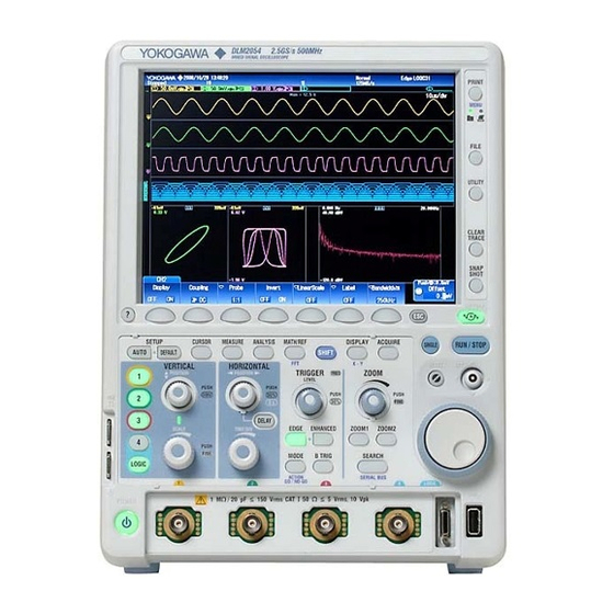
Chapter 1 Component Names and Functions Front Panel and Rear Panel Front Panel DLM2024, DLM2034, and DLM2054 Description of the displayed contents → Section 1.3 DLM2054 2.5GS/s 500MHz MIXED SIGNAL OSCILLOSCOPE PRINT Soft keys MENU Use the soft keys to select items on the soft key menus that FILE appear during configuration. - Page 20 Video signal output option) terminal Use this terminal to supply power to Use this terminal to view the YOKOGAWA FET probes and DLM2000 display on an current probes. → Section 3.4 external display. USB port for PCs Use this port to connect the...
-
Page 21: Keys And Knobs
Keys and Knobs Vertical Axis and Channels CH1 to CH4 Keys and LOGIC Key (On 4-channel models) VERTICAL POSITION Displays a menu for turning analog signal input channels on and off, for expanding and PUSH reducing the vertical axis, and for setting the vertical position, coupling, probe type, offset 0DIV voltage, bandwidth limit, linear scaling, and waveform labels. - Page 22 1.2 Keys and Knobs B TRIG Key Use this key to set trigger combinations with the Edge or Enhanced trigger and to set the trigger B trigger type. LEVEL Knob Use this knob to set the trigger level. This knob has a push switch. You can press the knob to automatically set the trigger level to an appropriate level.
- Page 23 1.2 Keys and Knobs Display DISPLAY Key Use this key to configure the display. SHIFT+DISPLAY (X-Y) Key Press SHIFT and then press DISPLAY to display an X-Y display menu. Screen Capture Printing, Data Storage, History Waveforms, and Other Features PRINT Key Use this key to save and print screen capture data.
- Page 24 1.2 Keys and Knobs HELP (?) Key Turns on and off the help window, which explains various features. SHIFT Key Press this key once to access the features that are written in purple below each key. The shift key illuminates when the keys are shifted. Press the key again to clear the shifted state.
-
Page 25: Screens
Screens Normal Analog Signal Waveform Screen Channel information Scale and input coupling settings Waveform acquisition state Stopped Running Preview: Displayed when changing the Scale, Time/div, and othersettings while waveform acquisition is stopped. Trigger point Number of waveform acquisitions Trigger position Acquisition mode "Waiting for trig."... - Page 26 1.3 Screens Screen Displaying Zoom Waveforms Displays the zoom position relative to the entire waveform when normal analog waveforms are not displayed. Z1 zoom range in Zoom position of zoom waveform Z2 Zoom position of zoom Z2 zoom range in the X direction waveform Z1 the X direction...
- Page 27 1.3 Screens Hierarchical Display of Setup Menus The higher-level setup menus are displayed using cascaded tags. Menu that is one level higher (CH2) Menu that is two levels higher (Ref Level) Index IM 710105-03E...
-
Page 28: Chapter 2 Making Preparations For Measurements
Chapter 2 Making Preparations for Measurements Handling Precautions Safety Precautions If you are using this instrument for the first time, make sure to thoroughly read the safety precautions given on pages viii to xi. Do Not Remove the Case Do not remove the case from the instrument. Some sections inside the instrument have high voltages and are extremely dangerous. - Page 29 2.1 Handling Precautions When Carrying the Instrument Remove the power cord and connecting cables. When carrying the instrument, either hold the handle or hold the instrument with both hands as shown in the figure below. WARNING • When you hold or put away the handle, be careful not to get your hand caught between the handle and the case.
-
Page 30: Installing The Instrument
Installing the Instrument WARNING • Do not install the instrument outdoors or in locations subject to rain or water. • Install the instrument so that you can immediately remove the power cord if an abnormal or dangerous condition occurs. CAUTION If you block the inlet holes on the left side or the outlet holes on the rear side of the DLM2000, the DLM2000 will become hot and may break down. - Page 31 2.2 Installing the Instrument Well-Ventilated Location Inlet holes are located on the left of the instrument. There are also exhaust holes on the rear side. To prevent internal overheating, allow for enough space around the instrument (see the figure below) and do not block the inlet and exhaust holes. 5 cm or more 5 cm...
- Page 32 2.2 Installing the Instrument Installation position Place the instrument in a horizontal position (see the figure below). Rubber stoppers can be attached to the four feet on the bottom of the DLM2000. Four rubber stoppers are included with the DLM2000. WARNING Do not place the instrument in any position other than those shown in the above figures.
-
Page 33: Connecting The Power
OFF. • Pour éviter tout risque de choc électrique ou d’incendie, utiliser exclusivement le cordon d’alimentation fourni par YOKOGAWA et prévu pour l’instrument. • Relier l’instrument à la terre pour éviter tout risque de choc électrique. Brancher le cordon d’alimentation sur une prise de courant à... - Page 34 2.3 Connecting the Power Connecting the Power Cord Check that both the main power switch of the DLM2000 is off. Connect the power cord plug to the power connector on the rear panel. Connect the other end of the cord to an outlet that meets the conditions below. Use the three-prong power outlet equipped with a protective earth terminal.
- Page 35 • Check that the correct voltage is coming to the power outlet. → Page 2-5 • Initialize the settings to their factory defaults by turning on the power switch while holding down the RESET key. If the instrument still does not work properly, contact your nearest YOKOGAWA dealer for repairs. Note •...
- Page 36 2.3 Connecting the Power Operations Performed When the Power Is Turned Off The settings immediately before the power switch is turned off are stored. Therefore, the next time the power is turned on, waveforms are measured using those settings. Note If you turn off the main power switch on the rear panel while the power switch on the front panel is turned on, the setup data immediately before the power switch is turned off will not be stored properly.
-
Page 37: Connecting The Probe
Connecting the Probe WARNING • Always turn off the power of the device under measurement before connecting the device under measurement to the instrument. It is extremely dangerous to connect or disconnect a measuring lead while the device under measurement is on. •... - Page 38 2.4 Connecting the Probe French AVERTISSEMENT • Toujours mettre l’appareil à mesurer hors tension avant de le brancher sur l’instrument. Il est extrêmement dangereux de brancher un câble de mesure lorsque l’appareil à mesurer est sous tension. • Ne pas dépasser les valeurs maximales de tension d’entrée, de tension de maintien ou de surtension admissible.
- Page 39 2.4 Connecting the Probe Connecting the Probe Connect a probe (or measurement input cable such as a BNC cable) to the input terminal on the bottom of the front panel. The input impedance is 1 MΩ ± 1.0% and approximately 20 pF or 50 Ω...
- Page 40 2.4 Connecting the Probe Specification of miniature passive probe (701946), after probe phase compensation On models with the /EX52, /EX54, /EX22, or /EX24 option, 701946 passive probes are provided in place of standard supplied probes. For details, see the manual that came with the probe. Item Specification Overall probe length...
- Page 41 Connecting FET Probe, Current Probe, Differential Probe, or Deskew Correction Signal Source If you are using the YOKOGAWA’s FET Probes, Current Probes, Differential Probes, or Deskew Correction Signal Source, use the Probe Power (option) on the DLM2000 rear panel for the power supply. For details on the connection procedure, see the manual that comes with the respective product.
- Page 42 Handling Precautions of the Probe Interface Terminals and Probe Power Terminals If you are connecting the YOKOGAWA’s FET Probes, Current Probes, Differential Probes, or Deskew Correction Signal Source to the Probe Power Terminals (option) on the rear panel, be sure that the total current of the four Probe Power Terminals and the four Probe Interface Terminals does not exceed 1.2 A.
-
Page 43: Compensating The Probe (Phase Correction)
Compensating the Probe (Phase Correction) Be sure to perform phase correction of the probe first when using a probe to make measurements. CAUTION Do not apply external voltage to the signal output terminal for probe compensation adjustment. Doing so may damage the internal circuitry. French ATTENTION Ne pas appliquer de tension externe sur la borne de sortie de signal afin d’ajuster... -
Page 44: App
2.5 Compensating the Probe (Phase Correction) Explanation Necessity of Phase Correction of the Probe The probe comes with its phase corrected approximately to match the input capacitance of the relevant oscilloscope. However, there is variance in the input resistance and input capacitance of each input channel of individual oscilloscopes. -
Page 45: Connecting Logic Probes
Connecting Logic Probes WARNING • Always turn off the power of the device under measurement before connecting the device under measurement to the instrument. • Do not apply an input voltage that exceeds the maximum input voltage. • To avoid electric shock, be sure to ground the instrument, and connect the ground of the probe and input connector to the ground of the item being measured. - Page 46 2.6 Connecting Logic Probes French AVERTISSEMENT • Toujours mettre l’appareil à mesurer hors tension avant de le brancher sur l’instrument. • Ne pas dépasser les valeurs maximales de tension d’entrée. • Pour éviter tout risque de choc électrique, relier l’instrument à la terre et brancher la terre de la sonde et du connecteur d’entrée sur la terre de l’appareil à...
- Page 47 2.6 Connecting Logic Probes Logic Signal Input Ports Connect the logic probe (701980/701981/701988/701989) to the logic signal input port. LOGIC MΩ / 20 pF 150 Vrms 50 Ω 5 Vrms, 10 Vpk Logic signal input port About the Logic Probe The logic probe (701980/701981/701988/701989) is designed exclusively for the logic signal input ports of the DLM2000.
-
Page 48: Attaching The Panel Sheet
Attaching the Panel Sheet Attach the supplied front panel sheet to the instrument as necessary. The front panel sheet that comes with the instrument is determined by the instrument’s language code. You can attach the panel sheet over the panel sheet that is affixed to the instrument when it is shipped from the factory. -
Page 49: Loading Roll Paper Into The Built-In Printer (Option)
This section explains how to load roll paper into the optional built-in printer. Roll Paper for Printers Only use roll paper specifically made for use with the DLM2000 series. The DLM2000 comes with one set of roll paper included. Use this when you first load roll paper into the built-in printer. -
Page 50: Index
2.8 Loading Roll Paper into the Built-In Printer (Option) Attaching the Roll Paper CAUTION • Do not touch the print head. If you do, you may burn yourself. • Do not touch the roll paper cutter section at the end of the printer cover. Doing so may cause injury. -
Page 51: Chapter 3 Basic Operations
Chapter 3 Basic Operations Key and Jog Shuttle Operations Key Operations How to Use Setup Menus That Appear When Keys Are Pressed The operation after you press a key varies depending on the key that you press. DISPLAY menu CURSOR menu Jog shuttle setting menu MODE menu MATH/REF menu... - Page 52 3.1 Key and Jog Shuttle Operations Entering Values Using the RESET ( ) and SET ( ) Keys When you use the jog shuttle to set a value, the jog shuttle setup menu shows a RESET key mark or a SET key mark. •...
-
Page 53: Entering Values And Strings
Entering Values and Strings Entering Values Using Dedicated Knobs You can use the following dedicated knobs to enter values directly. • POSITION knobs (VERTICAL and HORIZONTAL) • SCALE knob (VERTICAL) • TIME/DIV knob • LEVEL knob (TRIGGER) • ZOOM magnification knob Using the Jog Shuttle Select the appropriate item using soft keys, and change the value using the jog shuttle and the SET key. - Page 54 3.2 Entering Values and Strings Entering Character Strings Use the keyboard that appears on the screen to enter file names and comments. Use the jog shuttle and the SET key to control the keyboard and enter characters. Select from character strings Character insertion position you entered previously Move the character...
-
Page 55: Using Usb Keyboards And Mouse Devices
The operation of keyboards that have USB hubs or mouse connectors are not guaranteed. • For USB keyboards that have been tested for compatibility, contact your nearest YOKOGAWA dealer. USB Port for Peripherals Connect a USB keyboard to the USB connector for peripherals on the front or rear panel. - Page 56 1.1. Note • For USB mouse devices that have been tested for compatibility, contact your nearest YOKOGAWA dealer. • Some settings cannot be configured by a mouse without a wheel. Connection Procedure Connect a USB mouse to a DLM2000 USB connector for peripherals. You can connect or disconnect the USB mouse at any time regardless of whether the DLM2000 is on or off (hot-plugging is supported).
- Page 57 3.3 Using USB Keyboards and Mouse Devices Operating the DLM2000 Using a USB Mouse • Operations That Correspond to the Front Panel Keys (Top menu) Displaying the Top Menu Right-click on the display. A menu of the DLM2000 front panel keys appears. Selecting an Item from the Top Menu Click on the item that you want to select.
- Page 58 3.3 Using USB Keyboards and Mouse Devices Clearing the Menu To clear the menu, click outside of it. • Specifying Values The following description explains how to specify values for menu items that have a icon next to them. • If there are two icons next to a single menu item, click on the item to select an item to configure.
- Page 59 3.3 Using USB Keyboards and Mouse Devices • Selecting a file, directory, or media drive from the File List window. Click on a file, directory, or media drive to select it. Rotate the mouse wheel to scroll through the file list. To cancel your selection, click outside of the File List window.
-
Page 60: Synchronizing The Clock
Synchronizing the Clock This section explains how to set the DLM2000 clock, which is used to generate timestamps for measured data and files. The DLM2000 is factory shipped with a set date and time. You must set the clock before you start measurements. Procedure Press UTILITY key to display the Utility menu. - Page 61 3.4 Synchronizing the Clock Explanation Turning the Display On and Off (Display) Sets whether or not to display the date and time on the DLM2000 screen. Display Format (Format) You can display the date in one of the following formats. Year/Month (numeric)/Day Day/Month (numeric)/Year Day-Month (English abbreviation)-Year (the lower two digits)
-
Page 62: Performing Auto Setup
Performing Auto Setup Procedure Executing Auto Setup Press AUTO key. Auto setup is executed, and an Undo item appears. Undoing Auto Setup Press the Undo soft key to revert to the settings that were in effect before executing auto setup. Explanation The auto setup feature automatically sets the V/div, T/div, trigger level, and other settings to the most suitable values for the input signals. - Page 63 3.5 Performing Auto Setup Settings after the Execution of Auto Setup CH1 to CH4 settings Position 0 div Coupling FULL Offset Invert Acquisition settings Record Length The same as the value used before you executed auto setup However, if the record length is such that the DLM2000 cannot acquire waveforms in Single mode, the record length is set to the maximum record length at which the DLM2000 can acquire waveforms repeatedly.
-
Page 64: Resetting The Dlm2000 To Its Factory Default Settings
Resetting the DLM2000 to Its Factory Default Settings Procedure Resetting the DLM2000 to Its Factory Default Settings Press DEFAULT key. The DLM2000 is reset to its factory default settings. An Undo item appears. Undoing the Reset Operation Press the Undo soft key to revert to the previous settings. Explanation You can reset the DLM2000 settings to their factory default values. -
Page 65: Starting And Stopping Waveform Acquisition
Starting and Stopping Waveform Acquisition Procedure Starting or Stopping Waveform Acquisition. Press RUN/STOP key to start or stop waveform acquisition. The key is illuminated while the DLM2000 is acquiring waveforms. Acquiring Waveforms Using a Single Trigger Press SINGLE key to start waveform acquisition. The key is illuminated while the DLM2000 is acquiring waveforms. -
Page 66: Calibrating The Dlm2000
Calibrating the DLM2000 Procedure Press UTILITY key. Calibration Press the Calibration soft key. Executing Calibration Press the Cal Exec soft key to execute calibration. Turning Auto Calibration On or Off Press the Auto Cal soft key to select ON or OFF. Explanation Calibration Calibrates the following items. -
Page 67: Displaying Help
Displaying Help Procedure Displaying Help Press the help key (?) to display help. The table of contents and index appear in the left frame, and text appears in the right frame. Switching between Frames To switch to the frame that you want to control, move the SET key ( ) left and right. -
Page 68: Chapter 4 Operating The Dlm2000
Chapter 4 Operating the DLM2000 Applying Signals to Measure To help you understand basic oscilloscope operations, this chapter explains how to use the DLM2000 probe compensation signal and perform procedures from displaying waveforms to saving data. Connecting to the Power Supply Follow the procedure in section 2.3, "Connecting the Power,"... -
Page 69: Changing The Waveform Display Conditions
Changing the Waveform Display Conditions This section explains how to change vertical control settings such as the voltage scale and vertical position as well as horizontal control settings such as the time scale. Change these settings while waveform acquisition is in progress. Changing the Voltage Sensitivity from 500 mV/division to 200 mV/division Press the appropriate CH key of the channel whose scale you want to change (CH1 POSITION knob... - Page 70 4.2 Changing the Waveform Display Conditions Changing the Time Scale from 200 μs/div to 100 ms/div The time scale refers to the time per division of the grid. If you increase the time scale when the trigger mode is set to Auto or Auto Level, the DLM2000 switches from update display mode, in which a stationary waveform is updated, to roll mode display, in which waveforms flow from the right to the left of the screen.
-
Page 71: Changing The Trigger Settings
Changing the Trigger Settings The trigger settings determine which part of the acquired waveform to display. The main trigger settings are listed below. Trigger type Triggers can be classified into edge triggers and enhanced triggers. Trigger source The trigger source is the signal that is used to check for the trigger condition. Trigger slope Slope refers to the signal movement, such as from a low level to a high level (rising slope) or from a high level to a low level (falling slope). - Page 72 4.3 Changing the Trigger Settings Changing the Trigger Slope from Rising to Falling Press EDGE key. TRIGGER TRIG’D LEVEL Set Slope to falling ( ). PUSH Trigger point EDGE ENHANCED MODE B TRIG ACTION GO / NO-GO EDGE key Triggers on the falling edge Set the slope to falling Trigger level Index...
-
Page 73: Measuring The Waveform
Measuring the Waveform This section explains how to use vertical cursors to measure the displayed waveform's voltages and its period. Other convenient features such as computation and the automated measurement of waveform parameters can also be used to measure pulse and other periodic waveforms. -
Page 74: Zooming In On Or Out From The Waveform
Zooming in on or out from the Waveform You can expand or reduce a section of the displayed waveform along the time axis. The zoomed waveforms of two locations can be displayed along with the normal waveform. When zoom waveforms are displayed, zoom boxes appear in the normal waveform display frame to indicate the zoom positions. -
Page 75: Printing And Saving The Waveform
Printing and Saving the Waveform This section explains how to print the displayed waveform on the built-in printer (/B5 option) and how to save measured data or a screen capture to a storage medium. Printing a Screen Capture on the Built-in Printer Follow the procedure below to print a screen capture of the waveform. - Page 76 4.6 Printing and Saving the Waveform Saving Screen Capture Data to a Storage Medium Follow the procedure below to capture the current screen and save it to a file on a storage medium. Press SHIFT key, and then press PRINT (MENU) key. PRINT Press the Print To soft key to set the destination to File.
- Page 77 4.6 Printing and Saving the Waveform Saving Measured Data to a Storage Medium Follow the procedure below to save waveform data displayed on the screen to a storage medium. The vertical, horizontal, and trigger settings for the waveform are also saved in this process.
-
Page 78: Chapter 5 Specifications
Chapter 5 Specifications Signal Input Section Analog Signal Input Item Specifications Number of input channels DLM2022(710105), DLM2032(710115), DLM2052(710125): 2 (CH1 and CH2) DLM2024(710110), DLM2034(710120), DLM2054(710130): 4 (CH1 to CH4) Input coupling settings AC1MΩ, DC1MΩ, DC50Ω, and GND Input connector BNC connector Input impedance 1 MΩ... - Page 79 5.1 Signal Input Section Item Specifications Maximum record length Maximum record length for which repetitive acquisitions are possible No options: 1.25 M points On models with the /M1 option: 6.25 M points On models with the /M2 option: 12.5 M points On models with the /M3 option: 25 M points Maximum record length for which a single acquisition is possible.
-
Page 80: Triggering Section
Triggering Section Item Specifications Trigger modes Auto, Auto Level, Normal, Single, N Single The DLM2000 measures in Single mode when you start acquisition by pressing the SINGLE key or when you start acquisition by pressing the RUN/STOP key when the record length setting only allows for single acquisition. - Page 81 5.2 Triggering Section Item Specifications Selectable trigger delay -(Time length of the post-trigger section) to 10 s range Selectable hold-off time 20 ns to 10 s range Trigger type (A trigger) Edge: Triggers on the edge of a single trigger source The source can be set to a signal from CH1 to CH4, from logic bits 0 to 7, EXT, or LINE.
- Page 82 5.2 Triggering Section Item Specifications CAN FD: Triggers on CAN FD bus signals The source can be set to a signal from CH1 to CH4. Modes: SOF, Error Frame, ID, ID OR Bit Rate: Arbitration phase 250 k, 500 k, 1 Mbps, User Define For User Define, you can set a value from 20 k to 1 Mbps in 0.1-kbps steps.
- Page 83 5.2 Triggering Section Item Specifications Triggers on the specified field number, line number, or polarity in video signals of various broadcasting systems. The source can be set to a channel from CH1 to CH4. Mode: NTSC: Triggers on an NTSC (525/60/2) signal PAL: Triggers on a PAL (625/50/2) signal SDTV:...
-
Page 84: Time Axis
Time Axis Item Specifications Selectable time scale range 1 ns/division to 500 s/division Timebase accuracy* ±0.002% Time measurement ±(0.002% + 50 ps + 1 sample period) accuracy* * Values measured under standard operating conditions (see section 5.11 for details) after a 30-minute warm-up. Display Item Specifications... - Page 85 5.5 Features Item Specifications Logic channel threshold You can choose from the following preset threshold level settings. level preset CMOS (5V) = 2.5 V, CMOS (3.3V) = 1.65 V, CMOS (2.5V) = 1.25 V, CMOS (1.8V) = 0.90 V, ECL = -1.30 V Deskewing The waveform display position can be adjusted for CH1 to CH4 and LOGIC...
- Page 86 5.5 Features Item Specifications Record lengths Standard model: 1.25 k points, 12.5 k points, 125 k points, 1.25 M points, 6.25 M points (single only), 12.5 M points (interleave and single only) /M1(S) option: 1.25 k points, 12.5 k points, 125 k points, 1.25 M points, 6.25 M points, 25 M points (single only), 62.5 M points (interleave and single only) /M2 option: 1.25 k points, 12.5 k points, 125 k points, 1.25 M points, 12.5 M points, 62.5...
- Page 87 5.5 Features Item Specifications Accumulation Accumulates waveforms with gradually decreasing intensity for the specified amount of time. The accumulation time can be set to a value from 100 ms to 100 s or to infinite. Intensity and color modes can be selected. Intensity: Accumulates waveforms using separate channel colors with gradually decreasing intensity.
- Page 88 5.5 Features Item Specifications History waveform searching You can search for waveforms that meet specified conditions, display detected history waveforms, and list the timestamps of the waveforms. You can set a search condition to search for history waveforms that enter a rectangular zone (Simple) or set four conditions4 and search on the AND or OR logic of these conditions.
- Page 89 5.5 Features Item Specifications GO/NO-GO determination A specific action can be executed when the GO/NO-GO result is NO-GO. You can set the number of times to execute the action in terms of the number of waveform acquisitions or the number of determinations. Up to four conditions can be set, and the four conditions can be combined using AND or OR logic to perform determination.
- Page 90 5.5 Features Screen Capture Data Printing and Saving Item Specifications Built-in printer (option) Prints screen captures in one of the following output formats. HardCopy: Prints the displayed screen image. Normal: Prints only the waveform area of the displayed screen image. The menu is not printed.
- Page 91 5.5 Features Other Features Item Specifications Default setup Resets the DLM2000 to its factory default settings. The following settings are not reset: date and time settings, communication interface settings, settings stored to the internal memory, and language settings. The Undo command can be used to revert to the previous settings. Auto setup Automatically sets the voltage scale, time scale, trigger, and other settings to the most suitable values for the input signals.
-
Page 92: Built-In Printer (/B5 Option)
Built-in Printer (/B5 Option) Item Specifications Print system Thermal line dot system Dot density 8 dots/mm Sheet width 112 mm Storage Internal Memory Item Specifications Media type SD memory card Memory size Standard model: Approx. 300 MB /C8 option: Approx. 1.8 GB /C9 option: Approx. -
Page 93: Auxiliary I/O Section
Auxiliary I/O Section External Trigger Input (TRIG IN) Item Specifications Connector type Input bandwidth * DC to 100 MHz Input impedance Approx. 1 MΩ, approx. 20 pF Maximum input voltage ±40 V (DC + ACpeak) or 28 Vrms (At 1 MHz and higher, the voltage decreases at 20 dB/decade down to ±5 V (DC+ACpeak) or 3.5 Vrms.) Input range ±2 V (DLM2024, DLM2034, DLM2054). -
Page 94: 5.10 Computer Interface
5.10 Computer Interface GP-IB (Option) Item Specifications Electrical and mechanical Complies with IEEE St’d 488-1978 (JIS C 1901-1987) specifications Functional specifications SH1, AH1, T6, L4, SR1, RL1, PP0, DC1, DT0, C0 Protocol Complies with IEEE St’d 488.2-1992 Code ISO (ASCII) Mode Addressable mode Addresses... -
Page 95: 5.11 General Specifications
5.11 General Specifications Item Specifications Standard operating Ambient temperature: 23 ± 5°C conditions Ambient humidity: 55 ± 10%RH Supply voltage and Within 1% of rating frequency errors: Warm-up time At least 30 minutes Storage environment Temperature: –20 to 60°C Humidity: 20 to 80%RH (no condensation) Altitude: 3000 m or less... - Page 96 Cable conditions Logic signal input port Attach ferrite cores (TDK: ZCAT2035-0930A, YOKOGAWA: A1190MN) to the both end of logic probe cables. Probe power terminal Attach ferrite cores (TDK: ZCAT1325-0530A, YOKOGAWA: A1181MN) to the DLM2000 end of B9852MJ dedicated power cables, which is sold separately.
- Page 97 5.11 General Specifications Item Specifications Immunity Compliant standard EN 61326-1 Table 2 (for use in industrial locations) EN 61326-2-1 (Applicable to the 710105, 710110, 710115, 710120, 710125, 710130, 701938, 701939, 701913, 701924, 701928, 701929, 701988, 701989) Influence in the immunity testing environment (criteria A) Noise increase: Within ±200 mV (when using the 701938 or 701939) Within ±2 V (when using the 701913 or 701924)
-
Page 98: 5.12 External Dimensions
5.12 External Dimensions Unit: mm Unless otherwise specified, tolerances are ±3% (however, tolerances are ±0.3 mm when below 10 mm). Rear view Index DLM2054 2.5GS/s 500MHz MIXED SIGNAL OSCILLOSCOPE PRINT MENU FILE UTILITY CLEAR TRACE SNAP SHOT SETUP CURSOR MEASURE ANALYSIS MATH/REF DISPLAY... -
Page 99: Appendix
Appendix Appendix 1 Relationship between the Time Axis Setting, Record Length, and Sample Rate When the Record Length Is 1.25 k points (This record length can be selected on all models) Intpl: Interpolation Mode Rep: Repetitive Sampling Mode When High Resolution mode is off When High Resolution mode is on Settings When Interleave mode is off... -
Page 100: Appendix 1 Relationship Between The Time Axis Setting, Record Length, And Sample Rate
Appendix 1 Relationship between the Time Axis Setting, Record Length, and Sample Rate When the Record Length Is 12.5 k points (This record length can be selected on all models) Intpl: Interpolation Mode Rep: Repetitive Sampling Mode When High Resolution mode is off When High Resolution mode is on Settings When Interleave mode is off... - Page 101 Appendix 1 Relationship between the Time Axis Setting, Record Length, and Sample Rate When the Record Length Is 125 k points (This record length can be selected on all models) Intpl: Interpolation Mode Rep: Repetitive Sampling Mode When High Resolution mode is off When High Resolution mode is on Settings When Interleave mode is off...
- Page 102 Appendix 1 Relationship between the Time Axis Setting, Record Length, and Sample Rate When the Record Length Is 1.25 M points (This record length can be selected on all models) Intpl: Interpolation Mode Rep: Repetitive Sampling Mode When High Resolution mode is off When High Resolution mode is on Settings When Interleave mode is off...
- Page 103 Appendix 1 Relationship between the Time Axis Setting, Record Length, and Sample Rate When the Record Length Is 6.25 M points (This record length can be selected when there is no memory option or on DLM2000s Intpl: Interpolation Mode with the /M1(S) option) Rep: Repetitive Sampling Mode When High Resolution mode is off When High Resolution mode is on...
- Page 104 Appendix 1 Relationship between the Time Axis Setting, Record Length, and Sample Rate When the Record Length Is 12.5 M points (This record length can be selected when there is no memory option or on DLM2000s Intpl: Interpolation Mode with the /M2 option) Rep: Repetitive Sampling Mode When High Resolution mode is off When High Resolution mode is on...
- Page 105 Appendix 1 Relationship between the Time Axis Setting, Record Length, and Sample Rate When the Record Length Is 25 M points (This record length can be selected on DLM2000s with the /M1(S) or /M3 option) Intpl: Interpolation Mode Rep: Repetitive Sampling Mode When High Resolution mode is off When High Resolution mode is on Settings...
- Page 106 Appendix 1 Relationship between the Time Axis Setting, Record Length, and Sample Rate When the Record Length Is 62.5 M points (This record length can be selected on DLM2000s with the /M1(S) or /M2 option) Intpl: Interpolation Mode Rep: Repetitive Sampling Mode When High Resolution mode is off When High Resolution mode is on Settings...
- Page 107 Appendix 1 Relationship between the Time Axis Setting, Record Length, and Sample Rate When the Record Length Is 125 M points (This record length can be selected on DLM2000s with the /M2 or /M3 option) Intpl: Interpolation Mode Rep: Repetitive Sampling Mode When High Resolution mode is off When High Resolution mode is on Settings...
- Page 108 Appendix 1 Relationship between the Time Axis Setting, Record Length, and Sample Rate When the Record Length Is 250 M points (This record length can be selected on DLM2000s with the /M3 option) Intpl: Interpolation Mode Rep: Repetitive Sampling Mode When High Resolution mode is off When High Resolution mode is on Settings...
Need help?
Do you have a question about the DLM2000 Series and is the answer not in the manual?
Questions and answers