Advertisement
Quick Links
Operation
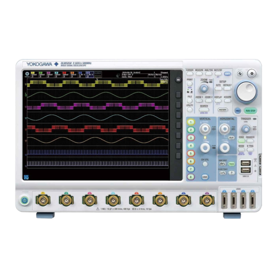
DLM5034, DLM5038, DLM5054, DLM5058
Mixed Signal Oscilloscope
Guide
Operation Guide
This operation guide explains the basic operations of this instrument. In this guide, operations are
described in steps from "Preparation" to "Displaying Waveforms," "Measuring Waveforms," and "Saving
Screen Captures."
For handling precautions and warnings of this instrument, read the Getting Started Guide (IM
DLM5058-03EN) thoroughly, and use the instrument properly.
1st Edition: September 2020 (YMI)
All Rights Reserved, Copyright © 2020, Yokogawa Test & Measurement Corporation
Printed in Japan
Workflow
Displaying the Waveform
Use auto setup to display the input signal (the instrument's probe compensation signal).
Changing the Waveform Display Conditions
Change the vertical axis, horizontal axis, and edge trigger settings.
Measuring the Waveform
Use vertical cursors to measure the time and voltage of the displayed waveform.
Saving the Waveform Screen Image
Save the displayed screen image as data.
Using the Instrument according to the Workflow
What to Prepare
•
The instrument. This guide explains the DLM5058 as an example.
•
Power cord that complies with the standard specified by the country or region that the instrument
will be used in
1
•
Included passive probe (701937)
•
Manual
Printed
Operation Guide
IM DLM5058-04EN
Getting Started Guide
IM DLM5058-03EN
PDF data
Features Guide & Users
(contained in
Manual.pdf
the CD)
•
Adjustment screwdriver (used in the phase correction of probes)
DLM5000
Power cord
1 Miniature passive probe 701949 is included with options /E2 and /E3.
2 Use a non-metallic adjustment driver that matches the dimensions of the probe phase
adjustment hole.
Driver bit dimensions (reference)
Tip shape: – (minus)
W
Tip thickness (W): 0.4 mm to 0.5 mm
Tip width (W): 1.3 mm to 2.5 mm
L
Measurement Preparation
1.
Turn on the power switch.
See section 2.3, "Connecting the Power Supply and Turning the Power Switch On and Off," in
the Getting Started Guide (IM DLM5058-03EN).
2.
Connect a probe to the instrument's input terminal (CH1).
See section 2.4, "Connecting Probes," in the Getting Started Guide.
3.
Correct the probe phase.
See section 2.5, "Correcting a Probe Phase," in the Getting Started Guide.
Phase adjustment
hole
IM DLM5058-04EN
1st Edition
This document. Explains the basic operations of this
instrument in steps.
Explains the handling precautions and warnings of
this instrument, how to connect the power supply, how
to turn the power switch on and off, how to connect
probes, how to correct the probe phases, and other
common operations.
Before using the instrument, be sure to read the
handling precautions and warnings.
Features Guide (IM DLM5058-01EN) and User's
Manual (IM DLM5058-02EN). Explain the features of
this instrument and how to configure them.
2
Passive probe
1
Manual
Probe compensation
signal output terminal
Functional ground
terminal
Displaying the Waveform
Here, use the instrument's probe compensation signal (frequency: approx. 1 kHz, amplitude: approx. 1 V,
square wave signal) for the input signal.
1.
Press AUTO to execute auto setup.
1
When you execute auto setup, the voltage scale (V/div), time scale (Time/div), trigger level, and the like
are automatically set to values suitable for the input signal.
* The auto setup feature may not work properly for signals that include a DC component or high-
frequency components.
To measure the voltage with high accuracy, adjust the vertical scale so that the input signal is
measured with the largest possible amplitude.
Changing the Vertical Axis Settings
Change the vertical scale (voltage sensitivity) from 500 mV/div to 200 mV/div to increase the waveform
amplitude. Setting the voltage sensitivity means setting the voltage per grid division (V/div).
1.
Press CH (
1
2.
Use the SCALE knob to change the voltage sensitivity to 200 mV/div.
1
2
Measurements may not be performed correctly in this condition. Lower the vertical position to that the
entire waveform can be seen.
3.
Use the POSITION knob to move the vertical position down by 2 divisions.
3
Adjustment
screwdriver
2
Vertical
position (
The ground level
(
) also moves
along with the
waveform.
For details on the vertical axis, see chapter 1, "Vertical Axis (Analog Signal)," in the Features
Guide (IM DLM5058-01EN).
Voltage scale: 500 mV/div
*
).
The waveform is expanded vertically
causing a portion of the waveform to
go off the screen.
Voltage sensitivity: 200 mV/div
Lowering the vertical position causes
the entire waveform to be seen.
2 div
)
nbn Austria GmbH
Riesstraße 146, 8010 Graz
Tel. +43 316 40 28 05 | Fax +43 316 40 25 06
nbn @ nbn. at
www. nbn. at
IM DLM5058-04EN 1/2
Advertisement

Subscribe to Our Youtube Channel
Related Manuals for YOKOGAWA DLM5034


Summary of Contents for YOKOGAWA DLM5034
- Page 1 For handling precautions and warnings of this instrument, read the Getting Started Guide (IM DLM5058-03EN) thoroughly, and use the instrument properly. 1st Edition: September 2020 (YMI) All Rights Reserved, Copyright © 2020, Yokogawa Test & Measurement Corporation Printed in Japan IM DLM5058-04EN...
- Page 2 Changing the Horizontal Axis Settings Changing the Trigger Position from 50% (screen center) to 30% When you start waveform acquisition, the instrument triggers according to the specified conditions Change the horizontal (time) scale from 200 µs/div to 100 µs/div. Setting the time scale means setting and displays the waveform captured in the acquisition memory.
Need help?
Do you have a question about the DLM5034 and is the answer not in the manual?
Questions and answers