
Related Manuals for Omega SP-013


Summary of Contents for Omega SP-013
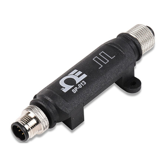
- Page 1 User’s Guide Shop online at omega.com e-mail: info@omega.com For latest product manuals: www.omegamanual.info SP-013 Digital Interface Smart Probe P a g e...
- Page 2 Tel: (203) 359-1660 Fax: (203) 359-7700 e-mail: info@omega.com The information contained in this document is believed to be correct, but OMEGA accepts no liability for any errors it contains and reserves the right to alter specifications without notice. P a g e...
-
Page 3: Table Of Contents
ON/OFF Functions ................................12 4.4.2.2 Pulse-Width Modulation (PWM) ............................ 12 4.4.3 Setting Alarms ..............................12 ON/OFF Control ............................. 13 Appendix: SP-013 Registers........................14 Digital Descriptor ............................14 5.1.1 Digital Measurement Types ..........................14 5.1.2 Digital Data Type/Format ........................... 15 5.1.2.1 Data Type .................................. - Page 4 5.2.5 DIO IPSO Definition ............................19 5.2.5.1 Sensor Trigger Function ..............................19 5.2.6 DIO Input Circuitry .............................. 19 Outputs ................................. 20 5.3.1 PWM Rate................................20 5.3.2 Active State................................. 20 5.3.3 Output Drive ............................... 20 5.3.4 Output Type................................ 20 Specifications ............................21 P a g e...
-
Page 5: Notes, Warnings, And Cautions
/ or damage to your equipment. The following labels identify information that is especially important to note: Note: Provides you with information that is important to successfully setup and use the SP-013. Caution or Warning: Tells you about the risk of electrical shock. -
Page 6: Introduction
M12 8-pin connector. The optional M12.5-S-M-FM connector can be utilized to easily connect wire leads to your SP-013. The SP-013 may be configured to monitor the on/off state of the input signals, the pulse rate/ duty cycle of the primary input, or the pulse delay between the two signals. -
Page 7: Hardware Setup
3 Hardware Setup Connecting your Layer N Smart Interface The SP-013 requires a Layer N Smart Interface to connect to your computer. Use the M12 8-Pin Connector diagram below to connect your SP-013 to your Layer N Smart Interface. Name... -
Page 8: Communication Interface
USB Serial Communication Interface USB Communication Interface • Connection Type: Select the type of connection you have between your SP-013 and your computer. • Command Timeout: The maximum time (in milliseconds) for a command to be completed before the command is aborted. -
Page 9: Digital Inputs Interface
Digital Inputs Interface The SP-013 accepts digital pulse inputs and may be configured to monitor the on/off state of the 3 input signals, the pulse rate or pulse duty cycle of the primary input, or the pulse delay between two signals. To use these features, follow these... - Page 10 Each of the three input pins can be independently set to either have an internal 1.5k Pull Up or Pull Down and can be set to be either Active High or Active Low. Some typical circuits are shown below: 10 | P a g e...
-
Page 11: Configurable Digital I/O
Configurable Digital I/O The Layer N SP-013 features 2 configurable digital I/O pins. These can be used for a myriad of applications including driving relays, physical alarms, or sensing dry contacts like door switches. Name Function Pin 1 DIO 0... -
Page 12: On/Off Functions
4.4.2.1 ON/OFF Functions I/O signals can be changed between Active High, Active Low, and inactive. Option Value Description When the output is inactive, it is in a high impedance state. Active HIGH When the output is active, it is in a high impedance state. Set output inactive Value Set output active... -
Page 13: On/Off Control
ON/OFF Control To configure ON/OFF Control on a device, navigate to the Output Configuration Tab in SYNC and click on the icon located to the right of the available outputs. Clicking the icon will open Define ON/OFF Control dialog box as seen below. Choose the input with the active alarm that you would like to control and set your preferred parameters. -
Page 14: Appendix: Sp-013 Registers
The following Appendix provides the registers and list index for the Layer N SP-013 Digital Input Smart Probe. This information is intended to aid users who will be making configurations and adjustments to their Layer N SP-013 Digital Input Smart Probe through the Command Line Interface or other custom interfaces. -
Page 15: Digital Data Type/Format
The 4-bit Data Type field determines the type of data of the specific sensor. 5.1.2.2 Factory Calibrate No Factory calibration is used on the SP-013. 5.1.2.3 Sensor Writeable If the Sensor Writeable bit is set the sensor value may be overwritten with a preset value. This capability is useful in sensors such as up/down counters, where a preset, or possibly a zero value must be written to the sensor value. -
Page 16: Assigned
5.1.3.4 Assigned The Assigned bit will always read as 0. Refer to the Smart Sensor Device Interface documentation for further information. 5.1.3.5 Available The Available bit will always read as 0. Refer to the Smart Sensor Device Interface documentation for further information. -
Page 17: Sensor Trigger Function
5.1.5.1 Sensor Trigger Function The Sensor Trigger function is used to reset the IPSO min/max values as well as controlling the Calibration process. Sensor Trigger Function Reset Min/Max Calibration Calibration Calibration Capture Capture Calibration Reset Status Mode High Start Setting the Reset Min/Max bit to 1 will reset the Min/Max values recorded by the IPSO process. No User Calibration process is supported on the Digital inputs and all configuration bits should be written as 0. -
Page 18: Sensor Writeable
5.2.2.3 Sensor Writeable If the Sensor Writeable bit is set the sensor value may be overwritten with a preset value. This capability is useful in sensors such as up/down counters, where a preset, or possibly a zero value must be written to the sensor value. 5.2.2.4 Smart Sensor Refer to the Smart Sensor Device Interface documentation. -
Page 19: Dio Ipso Definition
5.2.5 DIO IPSO Definition The DIO input IPSO definition provides signal range, measured min/max values, IPSO object type information. Offset Name Value Description 0x00 Sensor Type 3349 Bit Mapped Digital 0x02 Precision Provides reading of xxx 0x04 Sensor Trigger Function See section Sensor Trigger Function 0x08 Min Measured... -
Page 20: Outputs
5.3.4 Output Type The SP-013 probe supports NULL (0), ON/OFF (1) or PWM (2) outputs. When set to NULL the output signal will be left in a high impedance state. When set to ON/OFF the Rate information has no affect. -
Page 21: Specifications
6 Specifications INPUT POWER Voltage: 2.8 V - 3.3 V DIO DIGITAL INPUTS = 2.2 V inHighThreshold = 0.3 V inLowThreshold = 30 V inMAX DIO DIGITAL OUTPUTS 2x Open Drain 100 mA max = 30 V ACCURACY Type Range Operating Conditions Accuracy Frequency (f) - Page 22 Department will issue an Authorized Return (AR) number immediately upon phone or written request. Upon examination by OMEGA, if the unit is found to be defective, it will be repaired or replaced at no charge. OMEGA’s WARRANTY does not apply to defects resulting from any action of the purchaser, including but not limited to mishandling, improper interfacing, operation outside of design limits, improper repair, or unauthorized modification.
- Page 23 Where Do I Find Everything I Need for Process Measurement and Control? OMEGA…Of Course! Shop online at omega.com TEMPERATURE M U Thermocouple, RTD & Thermistor Probes, Connectors, Panels & Assemblies M U Wire: Thermocouple, RTD & Thermistor M U Calibrators & Ice Point References M U Recorders, Controllers &...
Need help?
Do you have a question about the SP-013 and is the answer not in the manual?
Questions and answers