Table of Contents
Advertisement
Quick Links
UM2062
User manual
Firmware for the ST25DV-DISCOVERY boards
Introduction
This document describes the functionalities of the STSW-ST25DV001 firmware, developed
to fully exploit the capabilities of the ST25DV-DISCOVERY boards, based on ST25DV.
The ST25DV is an IC for contactless applications that can communicate with a
microcontroller through an I²C interface; this makes the ST25DV a dynamic tag. On the RF
side, the reader (for instance a smart phone) can retrieve and update the content of the tag
when close to it.
The reader communicates with the ST25DV-DISCOVERY board using the ISO 15693
protocol, while the STM32F405 microcontroller communicates with the ST25DV through an
I²C bus.
With this discovery kit, the ST25DV can be programmed with different contents, following
the NFC Forum standard. This means that a smart phone can read it natively, without any
specific application being previously installed.
A specific fast transfer mode can be used to transfer data directly to the microcontroller,
without using the embedded EEPROM.
October 2021
UM2062 Rev 3
1/55
www.st.com
1
Advertisement
Table of Contents

Related Manuals for ST ST25DV-DISCOVERY


Summary of Contents for ST ST25DV-DISCOVERY
- Page 1 Introduction This document describes the functionalities of the STSW-ST25DV001 firmware, developed to fully exploit the capabilities of the ST25DV-DISCOVERY boards, based on ST25DV. The ST25DV is an IC for contactless applications that can communicate with a microcontroller through an I²C interface; this makes the ST25DV a dynamic tag. On the RF side, the reader (for instance a smart phone) can retrieve and update the content of the tag when close to it.
-
Page 2: Table Of Contents
STM32F405 ..........7 ST25DV-DISCOVERY boards ........8 2.3.1... - Page 3 List of tables List of tables Table 1. FTM commands list ............53 Table 2.
- Page 4 Figure 5. ST25DV-DISCOVERY features menu display ........11 Figure 6.
- Page 5 List of figures Figure 48. Smart phone and Multi records editor display ........45 Figure 49.
-
Page 6: List Of Acronyms And Notational Conventions
List of acronyms and notational conventions List of acronyms and notational conventions Acronyms APB: Advanced peripheral bus AAR: Android™ application record ® BLE: Bluetooth Low Energy CAN: Controller area network GPS: Global positioning system GPO: General purpose output H2R: Host to reader IEC: International electrotechnical commission ISO: International organization for standardization MCU: Micro controller unit (microcontroller) -
Page 7: Overview
Overview Overview ST25DV The ST25DV is a dynamic tag IC for contactless applications (ISO 15693). It manages the RF communication with a reader. It also includes frame coding, RF modulation and manages the anti-collision process. The ST25DV works as an NFC Forum Type 5 tag, supporting detection, read and write operations. -
Page 8: St25Dv-Discovery Boards
Alarm systems, video intercom and HVAC • Home and audio appliances ST25DV-DISCOVERY boards The ST25DV-DISCOVERY is an evaluation kit, which allows the user to evaluate the performance of the ST25DV dynamic tag. The kit is composed of two boards: • motherboard •... -
Page 9: St25Dv Daughter Board
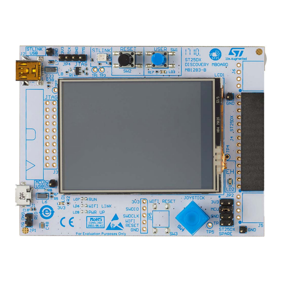
Overview Figure 2. ST25DX-DISCOVERY motherboard MB1283-B 2.3.2 ST25DV daughter board This board embeds the ST25DV NFC device and a 31 mm x 30 mm, 13.56 MHz double layer inductive etched antenna (no need for tuning components). The ST25DV communicates with the STM32F405VG 32-bit MCU via the I²C bus. Figure 3. -
Page 10: Firmware Description
• An NFC reader with a dedicated PC software. ST25PC-NFC software embeds all features and demonstrations to be used with ST25DV-DISCOVERY board. Refer to UM2444 (Software toolbox for NFC tags) for more information about it. The ST25DV is fully compliant with the NFC Forum Type 5 standard. This standard has been introduced recently, hence some features could not be fully supported by the oldest smart phones. -
Page 11: Discover St25Dv Menu
• ST25DV states • Multi-areas and passwords Figure 5. ST25DV-DISCOVERY features menu display 3.2.2 RF GPO interrupt demonstration The ST25DV has a GPO that can be used to send interrupts to the microcontroller. Several kinds of event can be configured on the RF side to trigger the GPO interrupt. In this demonstration all possible interrupt sources are enabled, except the “RF activity”, which... -
Page 12: Figure 6. St25Dv-Discovery Interrupt Generation Display
Firmware description Figure 6. ST25DV-DISCOVERY interrupt generation display The event types and of the way to generate them are listed below: • Field On: place a reader near the ST25DV • Field Off: move a reader away from the ST25DV •... -
Page 13: Figure 7. Smart Phone Gpo Register Configuration
Using this software user is able to manage GPO and to send RF interrupts to the ST25DV- DISCOVERY. Figure 8 show the use of ManageGPO command. For additional information about ST25PC-NFC software, Refer to UM2444 (Software toolbox for NFC tags) for more information about it, available on www.st.com. UM2062 Rev 3 13/55... -
Page 14: Figure 8. Use Of Pc Software To Manage Gpo
RF field is approaching or when it leaves. The current consumption is simulated by a digital potentiometer set to 240 Ohm (plus the measurement resistor). Figure 9. ST25DV-DISCOVERY energy harvesting measurement display 14/55 UM2062 Rev 3... - Page 15 Note: For the Low power mode, the ST25DXSPARE jumper must be present on the ST25DV-DISCOVERY board on the MCU pin, and a 12-pin package must be used for the ST25DV. ST25DV multi area and password demonstration The ST25DV can be configured to define up to four different areas in memory. Each area may have a custom security level, requiring one of the three passwords to be provided in order to read and/or write the memory.
-
Page 16: Fast Transfer Mode Demo" Menu
Firmware description Smart phone and multi areas When the tag has been configured in multi areas, the ST25 NFC application can handle areas and present to the user areas and content. User can choose the desired area selecting the corresponding menu in the application drawer. In case of special protections in an area, the application displays security status information. -
Page 17: Figure 11. St25Dv-Discovery Fast Transfer Mode Display
Firmware description Figure 11. ST25DV-DISCOVERY Fast Transfer Mode display The picture and note icons, at the bottom left, point to a sub-menu that allows the user choose a picture or a random data buffer, that is transferred to a reader (see... -
Page 18: Figure 12. Smart Phone And Fast Transfer Mode Use Cases Display
ST25PC-NFC software delivered by STMicroelectronics and able drive some NFC reader to communicate with NFC tags. Refer to UM2444 (Software toolbox for NFC tags) for more information about it, available on www.st.com. Select “FTM Demos”, in ST25DV-DISCOVERY menu to access to “FTM demos”. 18/55 UM2062 Rev 3... -
Page 19: Figure 13. Ftm Demonstration Selection On St25Pc-Nfc
Firmware description Figure 13. FTM demonstration selection on ST25PC-NFC Figure 14 shows the user interface used to play every FTM demonstrations. UM2062 Rev 3 19/55... -
Page 20: Figure 14. Ftm Demonstration User Interface
Check board version (R2H) • Firmware Upgrade demo (R2H) • Send a picture: select a picture to be sent to the ST25DV-DISCOVERY board using FTM protocol (R2H) • Receive a picture: select a picture on the ST25DV-DISCOVERY board and transfer it on PC user interface using FTM protocol (H2R) •... -
Page 21: Figure 15. R2H Data Transfer Diagram
Firmware description Figure 15 details the communication flow from the reader to the host (R2H) through the ST25DV during data transfer. Figure 15. R2H data transfer diagram UM2062 Rev 3 21/55... -
Page 22: Figure 16. St25Dv-Discovery R2H Data Transfer In Progress
During the transfer the full length of data transmitted is displayed and a bar indicates the progress (see Figure 16). Figure 16. ST25DV-DISCOVERY R2H data transfer in progress When the transfer is successfully completed, the computed CRC and the transfer time are displayed on the screen (Figure 17). -
Page 23: Figure 18. St25Dv Drawer Menu (Mailbox Management, Ftm Demonstration, Stopwatch Demonstration)
Firmware description Smart phone and FTM data transfers Several menus accessible by the drawer menu are dealing with the fast transfer mode data transfers: • Mailbox management. Radio buttons give the current status of the mailbox, and this menu permits to enable/disable the mailbox feature. •... -
Page 24: Figure 19. Mailbox Status
Firmware description As prerequisite to any data transfers the mailbox has to be enabled, without any pending message. The correct status is shown in Figure Figure 19. Mailbox Status 24/55 UM2062 Rev 3... -
Page 25: Figure 20. Data Transfers From Reader To Tag Of A Random Buffer
Firmware description Figure 20. Data transfers from reader to tag of a random buffer Note: According to data size selected, the corresponding payload data is initialized with random values on which a CRC is computed to be sure that host computes the same data after transfers. -
Page 26: Figure 21. St25Dv-Discovery Firmware Upgrade: Password Check
Flash memory area where the firmware is stored is erased (Figure 21). Figure 21. ST25DV-DISCOVERY firmware upgrade: password check If the password is correct the user is authorized to start the transfer (Figure 22), if not, the... -
Page 27: Figure 24. Software End Transfer Status Display
When the transfer is successfully completed, the computed CRC and the transfer time are displayed (see Figure 25). In case of failure an error message is displayed. Figure 25. ST25DV-DISCOVERY firmware upgrade: transfer done To start the new firmware, simply touch the screen. UM2062 Rev 3 27/55... -
Page 28: Figure 26. Smart Phone And Firmware Upgrade Display
PC software and firmware upgrade Select “Firmware Upgrade” demonstration, then select a binary file to be downloaded to the ST25DV-DISCOVERY board. In order to start firmware upgrade, the user needs to select a password, then to click on “Start” button to start transfer to the board. -
Page 29: Figure 27. Firmware Upgrade Demonstration
Firmware description Figure 27. Firmware upgrade demonstration Reader to host image download This function allows sending data from the reader to the STM32F405. In this demonstration data are jpeg images, stored in the Flash memory and displayed when transfer is successful. - Page 30 Firmware description Picture upload steps: • Check the mailbox status (c.f. drawer menus). • Select “FTM demos” in drawer menu. • Click on “Send picture to tag” Select a picture in phone’s memory. Figure 28. Transfer from smart phone to tag 30/55 UM2062 Rev 3...
-
Page 31: Figure 29. Image Transfer Demonstration: Send A Picture
Firmware description Figure 29. Image transfer demonstration: send a picture Host to reader image upload This function allows the user to send data from the STM32F405 to the reader (H2R). In this demonstration data are jpeg images, data are written to the mailbox each time this is free, and the MCU is informed by the GPO when the mailbox message is read by the reader. -
Page 32: Figure 30. H2R Data Transfer Diagram
Firmware description Figure 30. H2R data transfer diagram To start this demonstration the user needs to perform an action on firmware side. The picture icon at bottom left allows the user to enter a new menu (see Figure 31), which lets the user choose between pictures to send to the reader. -
Page 33: Figure 31. St25Dv-Discovery Select Picture To Upload
Firmware description Figure 31. ST25DV-DISCOVERY Select picture to upload After selecting the picture to transfer, the firmware writes the first chunk in the mailbox and waits for the message to be read. During the transfer a file size and a progress bar are... -
Page 34: Figure 34. Transfer From Tag To Smart Phone
Firmware description Smart phone and picture download transfer Features: same as Smart phone and picture transfers. Picture download steps: • Check MB registers • Select “FTM demos” in the drawer menu • Received picture from tag button. Select a picture on the ST25 discovery kit. The transfer starts. -
Page 35: Figure 35. Image Transfer Demonstration: Receive A Picture
Firmware description Figure 35. Image transfer demonstration: receive a picture Host to reader data transfer This function allows sending data from the STM32F405 to the reader. In this demonstration data are random binary data, data are written to the mailbox each time it is free, and the MCU is informed, via the GPO, when the mailbox message is read by the reader Figure 30 shows the transfer between the MCU and the reader (the flow is identical to... -
Page 36: Figure 36. St25Dv-Discovery Select H2R Data Size To Transfer Display
Smart phone and H2R data transfer To start the demonstration after prerequisites setting checked, go to “FTM demos” menu. After having selected the buffer size to send from ST25DV-DISCOVERY board, user can click on “Receive data from tag” button to start the transfer. -
Page 37: Figure 38. H2R Data Transfer Demonstration
PC software and H2R data transfer Select “Receive a buffer in a file” demonstration, after the selection of the buffer size to be sent from ST25DV-DISCOVERY board user can click on “Start” button to start the transfer of data from the board. -
Page 38: Figure 39. St25Dv-Discovery Stopwatch Start
On the smart phone: open the ST25 NFC application, tap the ST25DV and go to the “Stopwatch Transfers” menu and click on Start button. Figure 39. ST25DV-DISCOVERY stopwatch start Smart phone and stopwatch transfers In this demonstration the smart phone sends, as fast as possible, stopwatch values (8-byte frames) to the MCU using the mailbox. -
Page 39: Nfc Ndef Demonstrations Menu
Multi record NDEF message ® • Bluetooth Low Energy OOB NDEF message (requires an additional BLE module) ® ® • Wi-Fi OOB NDEF message (requires an additional Wi-Fi module) Figure 41. ST25DV-DISCOVERY NFC NDEF demonstrations menu display UM2062 Rev 3 39/55... -
Page 40: Figure 42. St25Dv-Discovery Read Uri Display
Read any SMS that has been stored in the ST25DV memory (the SMS is displayed on the screen) Figure 43. ST25DV-DISCOVERY read SMS content display Note: If, when the MCU reads the ST25DV memory, it does not contain a SMS, an error message is displayed. -
Page 41: Figure 44. St25Dv-Discovery Read Email Content Display
Read any e-mail that has been stored in the ST25DV memory. The content of the e-mail is displayed on the screen. Figure 44. ST25DV-DISCOVERY read Email content display Note: If, when the MCU reads the ST25DV memory, it does not contain an e-mail, an error message is displayed. -
Page 42: Figure 45. St25Dv-Discovery Read Vcard Content Display
Firmware description Figure 45. ST25DV-DISCOVERY read vCard content display Smart phone and vCard NDEF Refer to Reading and writing NDEF on a smart phone with the ST25 application. Geolocation demonstration This menu presents how to manage the geolocation content in the ST25DV. -
Page 43: Figure 46. St25Dv-Discovery Read Geolocation Display
Firmware description Figure 46. ST25DV-DISCOVERY read Geolocation display Note: If, when the MCU reads the ST25DV memory, it does not contain a Geolocation, an error message is displayed. MyApp record demonstration This demonstration shows how to use a proprietary NDEF record to control an application running on the host MCU. -
Page 44: Figure 47. St25Dv-Discovery Myapp Demonstration Screen
Firmware description Figure 47. ST25DV-DISCOVERY MyApp demonstration screen Multi record demonstration This menu presents how to manage a multi record NDEF in the ST25DV. With the MCU, the user can • Store an NDEF message containing the ST25 URI (it can then be read with an NFC reader or a smart phone) •... - Page 45 The HID protocol is natively supported by Android™ 6.0 smart phones, and this demonstration allows the user to control a pointer on the paired phone, by touching the screen of the ST25DV-DISCOVERY board. The screen acts as a touch-pad. The user button on the ST25DV-DISCOVERY board acts as a select button.
- Page 46 ® This menu presents how to manage a Wi-Fi pairing content in the ST25DV. By default, the ® ST25DV-DISCOVERY board doesn't feature the Wi-Fi module, but the ST SPWF01 ® module can be added on it, acting as a mini-Wi-Fi access point.
-
Page 47: Figure 49. Smart Phone And Ndef Discover Display
Firmware description Figure 49. Smart phone and NDEF discover display Write an NDEF: Select “NDEF editor” and choose the NDEF type you would like to write. An editor according to the selected type is displayed. Figure 50. Smart phone and URL NDEF write menu display Clear EEPROM This menu allows the user to clear the EEPROM content. - Page 48 Firmware description Write an empty NDEF Erase the CCFile (replace the first four bytes of memory with 0xFF) Clear EEPROM (fill the whole memory with 0xFF). 48/55 UM2062 Rev 3...
-
Page 49: Appendix Aftm Protocol Details
The NFC Reader (ex: a smart phone) always is the initiator of all communications. The new protocol is available on MB1286 “ST25DV-Discovery board” and on MB1396 “ST25DV64KC-DISCO board”. Operating modes The protocol is able to operate in two modes: •... -
Page 50: Low-Level Protocol
FTM protocol details Figure 51. Example of transmission with three packets per segment Packet1 Packet2 Packet3 Packet4 Packet5 Packet6 Packet7 Segment1 Segment2 Segment3 (a CRC is computed (a CRC is computed (containing a single packet for those 3 packets) for those 3 packets) it also contains CRC) Data to send MS54572V1... -
Page 51: Figure 53. Structure Of A Status Packet
FTM protocol details A “Status Byte” is a single Byte sent in response to one or more received packets to indicate if the transmission was successful or not. Figure 53. Structure of a status packet Unused Bytes Status Byte (1 byte) MS54574V1 The control byte has the following content: •... -
Page 52: St Light Protocol
FTM protocol details ST Light Protocol On top of previous low level protocol, a light protocol is used to indicate the content of the data sent. This light protocol is used to send commands that can be understood by the receiver. - Page 53 FTM protocol details Note: Beware to confusion between "status bytes" used for acknowledging (SEGMENT_OK = 0x80, SEGMENT_ERROR = 0x81) and Command Status (CMD_OK = 0x81, CMD_ERROR = 0x82). The following commands are currently used: Table 1. FTM commands list Cmd Id Command name Data Response data...
-
Page 54: Revision History
– Figure 2: ST25DX-DISCOVERY motherboard MB1283-B, Figure 7: Smart phone GPO register configuration, Figure 10: Smart phone and area display, Figure 11: ST25DV-DISCOVERY Fast Transfer Mode display, Figure 18: ST25DV drawer menu (Mailbox management, FTM demonstration, Stopwatch demonstration), Figure 20: Data transfers... - Page 55 ST products and/or to this document at any time without notice. Purchasers should obtain the latest relevant information on ST products before placing orders. ST products are sold pursuant to ST’s terms and conditions of sale in place at the time of order acknowledgement.
Need help?
Do you have a question about the ST25DV-DISCOVERY and is the answer not in the manual?
Questions and answers