Table of Contents
Advertisement
Quick Links
Introduction
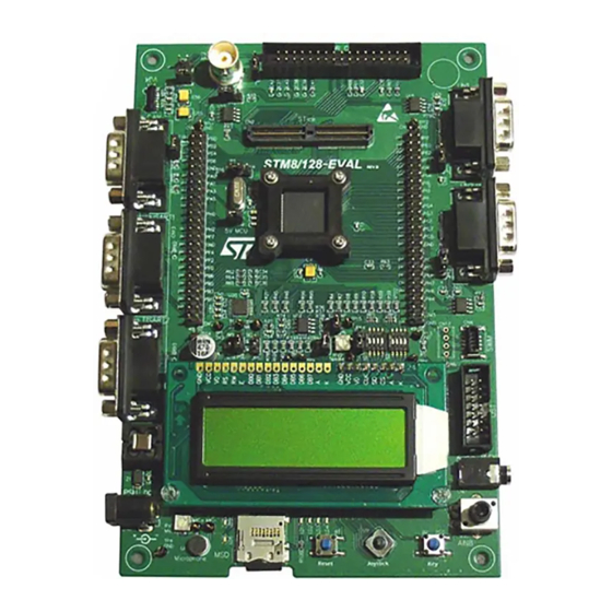
This document describes the demonstration firmware running on the STM8/128-EVAL
evaluation board. You can use it to evaluate the capabilities of the microcontroller and the
on-board peripherals.
The evaluation board is delivered with the demonstration firmware stored in the Flash
program memory of the microcontroller.
The firmware is based on the STM8S firmware library, and provides an example of how to
use this library. It is divided into various smaller demonstration applications (demos).
In case the STM8/128-EVAL evaluation board is not factory-programmed or the
demonstration application has been erased, you can reprogram the demonstration firmware
into the STM8S2xx Flash memory by following the instructions provided in
For more information about the evaluation board itself, please read the evaluation board
user manual.
Note:
To run some of the demonstration applications, the option byte must be configured
accordingly. Refer to
June 2009
STM8/128-EVAL demonstration firmware
Section 2.10: BEEPER
Doc ID 14320 Rev 3
User manual
demo.
UM0501
Section
3.
5/23
www.st.com
Advertisement
Table of Contents

Related Manuals for ST UM0501


Summary of Contents for ST UM0501
- Page 1 UM0501 User manual STM8/128-EVAL demonstration firmware Introduction This document describes the demonstration firmware running on the STM8/128-EVAL evaluation board. You can use it to evaluate the capabilities of the microcontroller and the on-board peripherals. The evaluation board is delivered with the demonstration firmware stored in the Flash program memory of the microcontroller.
-
Page 2: Table Of Contents
Contents UM0501 Contents User interface ..........7 Menu structure . -
Page 3: User Interface
UM0501 User interface User interface Menu structure The demonstration firmware user interface is based on a circular navigation menu, with submenus, item selection and back capability. Figure 1 shows the menu system of the demonstration. The top row of items represents the main menu. -
Page 4: Navigating Menus And Sub-Menus
User interface UM0501 Navigating menus and sub-menus To navigate the menus and sub-menus, perform the following actions as required. RIGHT: Navigates to the next menu or sub-menu items on the right. LEFT: Navigates to the next menu or sub-menu items on the left. -
Page 5: Demonstration Applications
The following sections provides a detailed description of each part of the demonstration firmware. Welcome screen and main menu After a board RESET, a welcome message is displayed on the first line, the ST logo is displayed moving on the second line and a melody is played (see Figure 3). -
Page 6: Help Mode
Demonstration applications UM0501 Help mode Pressing SEL from the main menu enters the Help mode. The following messages are displayed sequentially on the LCD screen with a few second delay. Figure 5. Help mode submenus LEFT or RIGHT to scroll menu... -
Page 7: Adc Demo 2
UM0501 Demonstration applications UP: Press the joystick UP to exit this demo. KEY: Press KEY repeatedly to enable the output of each converted value option in turn. LCD only LCD+Buzzer LCD+USART1 LCD+USART2 LCD+USART1+USART2 LCD+USART1+USART2+Buzzer LCD only etc... ADC demo 2 This is the same as ADC demo 1, except that the CN3 connector on the evaluation board is used to enter the analog voltage to be converted. -
Page 8: Timer Demo
Demonstration applications UM0501 TIMER demo This mode demonstrates the Timer peripheral operation. To run the TIMER demo, enter the timer start value (from 1 to 18 minutes) using the RV1 potentiometer (see Figure Figure 8. Entering the timer start value... -
Page 9: Pwm Demo 1
UM0501 Demonstration applications PWM demo 1 This mode demonstrates the Timer peripheral operating in PWM mode. Make sure that the JP14 jumper is installed in the bottom position (closer to the LCD). Entering the melody (see Figure 11): The first LCD line shows the position of the note to enter. -
Page 10: Pwm Demo 2
Demonstration applications UM0501 Figure 12. Saving the melody Save melody ? KEY=YES UP=NO LEFT/RIGHT: Press the joystick LEFT or RIGHT to navigate the notes. SEL: Press SEL to confirm a note and go to the next one. KEY: Press KEY to switch between edit and protected modes. -
Page 11: Beeper Demo
UM0501 Demonstration applications 2.10 BEEPER demo This mode demonstrates the 3 different frequencies that can be output on the BEEP pin. Prior to running the BEEPER demo, perform the following operations. ● Install the JP14 jumper in the top position (closer to the STM8S chip). -
Page 12: Microsd Demo
Demonstration applications UM0501 2.11 MICROSD demo This mode demonstrates the basic operation of the MicroSD card interface. When this mode is entered, it checks if a MicroSD card is inserted in the slot. – If no card is found, the message shown in Figure 16 is displayed. -
Page 13: Game Demo
UM0501 Demonstration applications Figure 19. Reading 512 bytes from the MicroSD card LEFT or RIGHT to see data Addr: 0x0001 Data: 0x01 2.12 GAME demo This little game is a kind of “fruit machine”. When you press SEL the numbers start rolling. Use the KEY button to stop each number. -
Page 14: System Demo
Demonstration applications UM0501 2.13 SYSTEM demo This menu is used to display system information. The message displayed on the LCD screen shows the clock source which is used (HSI, LSI or LSE) (see Figure 23). Figure 23. Displaying the clock source... -
Page 15: Upgrading The Demonstration Firmware
UM0501 Upgrading the demonstration firmware Upgrading the demonstration firmware To upgrade the demonstration firmware running on your board, go through the following steps. Download the latest version of STM8/128-EVAL demonstration firmware and related user manual from www.st.com/mcu/modules.php?name=mcu&file=familiesdocs&FAM=113 Extract the content of the downloaded zip file to the directory of your choice Power on the STM8/128-EVAL board and connect it to the Debug instrument Open STVD toolchain and proceed as follows. -
Page 16: Stm8S Peripherals Used
STM8S peripherals used UM0501 STM8S peripherals used The following table lists the STM8S peripherals used in each demo. Table 2. Peripherals used Peripheral Demo ADC2 ADC, TIMER and PWM demos EXTIT MicroSD demo GPIO All demos (buttons, LEDs) Clock Controller... -
Page 17: Demo Firmware Architecture
UM0501 Demo firmware architecture Demo firmware architecture This section describes the demo firmware architecture. It is divided into two parts. ● Library: contains the firmware library source files. These files do not need to be modified by the user. ●... -
Page 18: Revision History
Revision history UM0501 Revision history Table 3. Document revision history Date Revision Changes 08-Dec-2008 Initial release. 02-Mar-2009 Added Section 3: Upgrading the demonstration firmware. Added note about JP5 in Section 2.6 on page 17-Jun-2009 Updated KEY sequence in Section 2.7 on page... - Page 19 No license, express or implied, by estoppel or otherwise, to any intellectual property rights is granted under this document. If any part of this document refers to any third party products or services it shall not be deemed a license grant by ST for the use of such third party products or services, or any intellectual property contained therein or considered as a warranty covering the use in any manner whatsoever of such third party products or services or any intellectual property contained therein.
Need help?
Do you have a question about the UM0501 and is the answer not in the manual?
Questions and answers