Advertisement
Quick Links
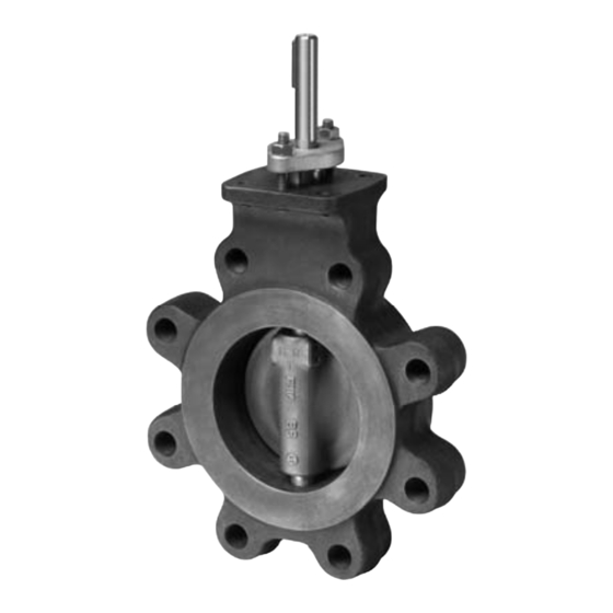
F6 Series 2-Way, Victaulic Butterfl y Valve
Technical Data
Service
chilled, hot water, 60% glycol
Flow characteristic
modifi ed equal percentage
Controllable fl ow range
82°
Sizes
2" to 12"
Type of end fi tting
grooved ANSI/AWWA (C606)
Valve materials*
Body
ductile iron ASTM A536, grade 65-45-12
Body fi nish
black alkyd enamel
Disc
electroless nickel coated ductile iron
Seat
EPDM
Shaft
416 stainless steel
Bearing
fi berglass with TFE lining
Body pressure rating
300 psi
Media temperature range
-30°F to 250°F [-34°C to 120°C]
Rangeability
100:1
Maximum close-off pressure
200 psi
Maximum velocity
20 FPS
*VIC
®
300 Masterseal™ as manufactured by Victaulic Company
Valve
Size
F650VIC
2"
115
F665VIC
2-1/2"
260
F680VIC
3"
440
F6100VIC
4"
820
F6125VIC
5"
1200
F6150VIC
6"
1800
F6200VIC
8"
3400
F6250VIC
10"
5800
F6300VIC
12"
9000
800-543-9038 USA
16
C
30°
40°
v
7
14
16
30
26
50
50
100
70
140
110
220
200
410
350
700
540
1080
866-805-7089 CANADA
• 200 psi (2" to 12") bubble tight shut-off
• Long stem design allows for 2" insulation
• Completely assembled and tested, ready for installation
Application
These valves are designed to meet the needs of HVAC and commercial
applications requiring bubble tight shut-off for liquids. Typical applications
include chiller isolation, cooling tower isolation, change-over systems, large
air handler coil control, bypass and process control applications. The large
C v values provide for an economical control valve solution for larger fl ow
applications.
Jobsite Note
Valves should be stored in a weather protected area prior to construction.
2-way
Valve
Nominal Size
C v
C v
DN
IN
90°
60°
[mm]
115
36
2
50
260
80
2½
65
440
140
3
80
820
250
4
100
1200
370
5
125
1800
560
6
150
3400
1050
8
200
5800
1800
10
250
9000
2790
12
300
50°
60°
70°
23
36
60
50
80
140
90
140
230
160
250
430
240
370
620
360
560
940
670
1050
1770
1150
1800
3020
1780
2790
4680
Suitable Actuators
Type
Non Fail-Safe
2-way
F650VIC
F665VIC
F680VIC
F6100VIC
F6125VIC
F6150VIC
F6200VIC
F6250VIC
F6300VIC
90°
115
260
440
820
1200
1800
3400
5800
9000
203-791-8396 LATIN AMERICA / CARIBBEAN
Fail-Safe
Spring
Electronic
Return
Advertisement

Related Manuals for Belimo F6 Series


Summary of Contents for Belimo F6 Series
- Page 1 F6 Series 2-Way, Victaulic Butterfl y Valve • 200 psi (2” to 12”) bubble tight shut-off • Long stem design allows for 2” insulation • Completely assembled and tested, ready for installation Application These valves are designed to meet the needs of HVAC and commercial applications requiring bubble tight shut-off for liquids.
- Page 2 8.553 [217.25] valve from the pipe. 4. Belimo SY and PR Series actuators are NEMA 4X rated. 5. Provide support for the actuator if it is mounted at any angle other than 90° vertical. 6. Installer is to use rigid type couplings for connecting the valve to the piping.
- Page 3 F7 Series 3-Way, Victaulic Butterfl y Valve • 200 psi (2” to 12”) bubble tight shut-off • Long stem design allows for 2” insulation • Completely assembled and tested, ready for installation Application These valves are designed to meet the needs of HVAC and commercial applications requiring bubble tight shut-off for liquids.
- Page 4 3. Dimension “D” allows for actuator removal without the need to remove the [92.12] valve from the pipe. 4. Belimo SY and PR Series actuators are NEMA 4X rated. 5. Provide support for the actuator if it is mounted at any angle other than 90° vertical.
- Page 5 The SY actuators are NEMA 4X rated and designed to meet the needs of HVAC and Commercial applications. Offered on Belimo standard and high performance valve series, these actuators are available for on/off and modulating applications. Depending on the application, they are available in 24 VAC/ VDC, 120 VAC and 230 VAC.
- Page 6 The SY actuators are NEMA 4X rated and designed to meet the needs of HVAC and Commercial applications. Offered on Belimo standard and high performance valve series, these actuators are available for on/off and modulating applications. Depending on the application, they are available in 24 VAC/ VDC, 120 VAC and 230 VAC.
- Page 7 The SY actuators are NEMA 4X rated and designed to meet the needs of HVAC and Commercial applications. Offered on Belimo standard and high performance valve series, these actuators are available for on/off and modulating applications. Depending on the application, they are available in 24 VAC/ VDC, 120 VAC and 230 VAC.
- Page 8 SY... Series Non-Spring Return Actuator Dimensions SY-2~6... SY-9~12... SY-7~8... Add to Dim A for MODEL DIM A (MAX) cover removal DIM B DIM C (MAX) DIM D Inches [mm] Inches [mm] Inches [mm] Inches [mm] Inches [mm] SY4~6 12.40 [315] 8.86 [225] 9.21 [234] 14.96 [380]...
- Page 9 Wiring for Control Valves On/Off, 24V, 120/230V 800-543-9038 USA 866-805-7089 CANADA 203-791-8396 LATIN AMERICA / CARIBBEAN...
- Page 10 Wiring for Control Valves Proportional, 24V, 120/230V Actuator: SY2…5-24MFT SY2...12-120MFT SY2...12-230MFT Hazard Identification INSTALLATION NOTES this manual. Read these carefully. CAUTION Indicates a potentially hazardous situation which, if not avoided, may result in minor or moderate injury. It may also be used to alert against unsafe practices.
- Page 11 Wiring for Control Valves On/Off, 24V, 110/120/230V SY Actuator Wiring Diagram, SY1…5-24 – Multiple Wiring SY1…12-110 (220) – Multiple Wiring Hazard Identification INSTALLATION NOTES Warnings and Cautions appear at appropriate sections throughout this Observe class 1 and class 2 wiring restrictions. manual.
-
Page 12: Application Notes
Wiring for Control Valves Proportional, Multiple Wiring, 24V Actuators: SY2...5-24MFT Hazard Identification INSTALLATION NOTES Warnings and Cautions appear at appropriate sections throughout this manual. Read these carefully. Observe class 1 and class 2 wiring restrictions. CAUTION Transformer sizing = SY actuator draw X 1.25 (safety margin) Indicates a potentially hazardous situation which, if (Ex. - Page 13 Wiring for Control Valves Proportional, Multiple Wiring, 120/230V Actuators: SY2...12-120MFT SY2...12-230MFT Hazard Identification INSTALLATION NOTES Warnings and Cautions appear at appropriate sections throughout this manual. Read these carefully. Observe class 1 and class 2 wiring restrictions. CAUTION Indicates a potentially hazardous situation which, if not avoided, may result in minor or moderate injury.
-
Page 14: Technical Data
AFBUP(-S)-X1, AFXUP(-S)-X1 Actuators, On/Off Models AFBUP-X1 AFBUP-S-X1 AFXUP-X1 AFXUP-S-X1 Technical Data Power supply 24...240 VAC -20% / +10%, 50/60 Hz 24...125 VDC ±10% Power consumption running holding 3.5 W Transformer sizing 7 VA @ 24 VAC (class 2 power source) 8.5 VA @ 120 VAC 18 VA @ 240 VAC Electrical connection... - Page 15 AFBUP(-S)-X1, AFXUP(-S)-X1 Actuators, On/Off Wiring Diagrams Provide overload protection and disconnect as required. CAUTION Equipment Damage! Actuators may be connected in parallel. Power consumption and input impedance must be observed. No ground connection is required. For end position indication, interlock control, fan startup, etc., AFBUP-S-X1 and AFXUP-S-X1 incorporates two built-in auxiliary switches: 2 x SPDT, 3A (0.5A) @250 VAC, UL Approved, one switch is fi...
- Page 16 AF Actuators, Multi-Function Technology Models AFX24-MFT-X1 AFX24-MFT-S-X1 w/built-in Aux. Switches 2*AFX24-MFT-X1 2*AFX24-MFT-S-X1 Technical Data Power supply 24 VAC, +/- 20%, 50/60 Hz 24 VDC, +20% / -10% Power running 7.5 W consumption holding 3 W Transformer sizing 10 VA (Class 2 power source) Electrical connection AFX...
- Page 17 AF Actuators, Multi-Function Technology Wiring Diagrams Actuators may also be powered by 24 VDC. IN4004 or IN4007 diode (IN4007 supplied, Belimo part number 40155). Triac A and B can also be contact closures. Control signal may be pulsed from either the Hot (Source) or Common (Sink) 24 VAC line.
- Page 18 DKRX24-3-T, DKRX(B)24-3-T N4(H) NEMA 2/NEMA 4X Actuators, On/Off, Floating Point Models DKRX24-3-T w/terminal block DKRX24-3-T N4 w/terminal block DKRB24-3-T N4H w/heater Technical Data Control on/off, fl oating point Power supply 24 VAC ± 20/-10% 50/60 Hz Power consumption running 12W / heater 33W holding 3W Transformer sizing 21 VA (class 2 power source) / heater 36 VA...
- Page 19 2.50 mm <100 m <20 m 1 m (L ) + 19 m (L = Belimo connecting cable, 1 m (4 x 0.75 mm = Customer cable = Actuator = Maximum cable length = Control unit = Belimo connecting cable, 1 m (4 x 0.75 mm m m ) ...3...
- Page 20 DKRX24-MFT-T, DKRX(B)24-MFT-T N4(H) NEMA 2/NEMA 4X Actuators, Multi-Function Technology Models DKRX24-MFT-T w/terminal block DKRX24-MFT-T N4 w/terminal block DKRB24-MFT-T N4H w/heater Technical Data Control 2 to 10 VDC, 4 to 20 mA (default) variable (VDC, fl oating point, on/off) Power supply 24 VAC ±...
- Page 21 Triac sink controller. The actuator internal common reference is not compatible. IN4004 or IN4007 diode. (IN4007 supplied, Belimo part number 40155). On/Off control The ZG-R01 500 Ω resistor converts the 4 to 20 mA control signal to 24 VAC Transformer 2 to 10 VDC, up to 2 actuators may be connected in parallel.
- Page 22 DRCX24-3-T, DRCX(B)24-3-T N4(H) NEMA 2/NEMA 4X Actuators, On/Off, Floating Point Models DRCX24-3-T w/terminal block DRCX24-3-T N4 w/terminal block DRCB24-3-T N4H w/heater Technical Data Control on/off, fl oating point Power supply 24 VAC ± 20/-10% 50/60 Hz 24 VDC ± 10% Power consumption running 9W / heater 29W holding 2W...
- Page 23 DRCX24-3-T, DRCX(B)24-3-T N4(H) NEMA 2/NEMA 4X Actuators, On/Off, Floating Point Wiring Diagrams 24 VAC Transformer Blk (1) Common – Line Volts CAUTION Equipment damage! Red (2) + Actuators may be connected in parallel. Power consumption and input impedance must be observed. a open Wht (3) + a closed...
- Page 24 DRX24-MFT-T, DRX24-MFT-T N4, DRCX24-MFT-T, DRCX(B)24-MFT-T N4(H) NEMA 2/NEMA 4X Actuators, Multi-Function Technology Models DRX24-MFT-T w/terminal block DRX24-MFT-T N4 w/terminal block DRCX24-MFT-T w/terminal block DRCX24-MFT-T N4 w/terminal block DRCB24-MFT-T N4H w/heater Technical Data Control 2 to 10 VDC, 4 to 20 mA (default) variable (VDC, fl...
- Page 25 Hot connection of the controller. Position feedback cannot be used with a Triac sink controller. The actuator internal On/Off Control common reference is not compatible. IN4004 or IN4007 diode. (IN4007 supplied, Belimo part number 40155). 24 VAC Transformer Blk (1) – Common Line...
- Page 26 GK Actuators, On/Off, Floating Point Models GKRB24-3-X1 GKRB24-3-5 GKB24-3-X1 Technical Data Power supply 24VAC ±20% 50/60Hz Power consumption 12W (3W) Transformer sizing 21VA (class 2 power source) Electrical connection 18 GA plenum rated cable ½" conduit connector protected NEMA 2 (IP54) 3 ft [1m] 10 ft [3m] 16 ft [5m] Overload protection electronic throughout 0 to 95 rotation...
-
Page 27: On/Off Control
= Control unit 2.50 mm <100 m <20 m 1 m (L ) + 19 m (L = Belimo connecting cable, 1 m (4 x 0.75 mm Blk (1) Common = Customer cable – = Actuator Line = Maximum cable length... - Page 28 GK Actuators, Multi-Function Technology Models GKRX24-MFT-X1 GKX24-MFT-X1 Technical Data GKX24-MFT-X1 Power supply 24VAC ±20% 50/60Hz 24VDC ±10% Power consumption 12W (3W) Transformer sizing 21VA (class 2 power source) Electrical connection 18 GA plenum rated cable ½" conduit connector protected NEMA 2 (IP54) 3 ft [1m] 10 ft [3m] 16 ft [5m] Overload protection electronic throughout 0 to 95 rotation...
- Page 29 GK Actuators, Multi-Function Technology Wiring Diagrams Provide overload protection and disconnect as required. Actuators may also be powered by 24 VDC. Position feedback cannot be used with Triac sink controller. The actuator internal common reference is not compatible. Control signal may be pulsed from either the Hot (source) or the Common (sink) 24 VAC line.
- Page 30 AM/AR Series Actuators, On/Off, Floating Point Models AMB24-3-X1 ARB24-3-X1 ARB24-3-5 Technical Data Power supply 24 VAC ± 20% 50/60 Hz 24 VDC ± 10% Power consumption running 2.0 W holding 0.2 W Transformer sizing 5.5 VA (class 2 power source) Electrical connection 3 ft, 18 GA plenum rated cable ½”...
- Page 31 AM/AR Series Actuators, On/Off, Floating Point Wiring Diagrams 24 VAC Transformer Blk (1) Common Line CAUTION Equipment damage! Volts Red (2) + Actuators may be connected in parallel. Power consumption and input impedance must be observed. Wht (3) + a open a closed Actuators may also be powered by 24 VDC.
- Page 32 AM/AR Series Actuators, Multi-Function Technology Models AMX24-MFT-X1 ARX24-MFT-X1 ARB24-MFT-5 Technical Data Power supply 24 VAC ± 20% 50/60 Hz 24 VDC ± 10% Power running 4 W consumption holding 1.25 W Transformer sizing 6 VA (class 2 power source) Electrical connection 3 ft [1m], 10 ft [3m], 16 ft [5m] 18 GA plenum rated cable ½”...
- Page 33 AM/AR Series Actuators, Multi-Function Technology Wiring Diagrams 24 VAC/DC Transformer Common Line Volts Actuators may also be powered by 24 VDC. Position feedback cannot be used with Triac sink controller. (–) Position Y Input The actuator internal common reference is not compatible. Feedback VDC (+) U Output Control signal may be pulsed from either the Hot (source)
- Page 34 GM/GR Actuators, On/Off, Floating Point Models GMB24-3-X1 GRB24-3-X1 GRB24-3-5 GRB24-3-7 Technical Data Power supply 24 VAC ± 20% 50/60 Hz 24 VDC ± 10% Power consumption running 4.0 W holding 2 W Transformer sizing 6 VA (class 2 power source) Electrical connection 3 ft, 18 GA appliance cable, 1/2”...
- Page 35 GM/GR Actuators, On/Off, Floating Point Wiring Diagrams CAUTION Equipment damage! Actuators may be connected in parallel. Power consumption and input impedance must be observed. Actuators may also be powered by 24 VDC. Actuators with plenum rated cable do not have numbers on wires; use color codes instead.
- Page 36 GM/GR Actuators, Multi-Function Technology Models GMX24-MFT-X1 GRX24-MFT-X1 GRB24-MFT-5 GRX24-MFT-7 Technical Data Power supply 24 VAC ± 20% 50/60 Hz 24 VDC ± 10% Power consumption running 4.5 W holding 2 W Transformer sizing 7 VA (class 2 power source) Electrical connection 3 ft, 18 GA appliance cable, 1/2”...
- Page 37 GM/GR Actuators, Multi-Function Technology Wiring Diagrams 24 VAC Transformer Common Line Volts + Hot Actuators may also be powered by 24 VDC. 500Ω Ω 1/4 watt Actuators with plenum rated cable do not have numbers on wires; use (–) Control Signal 4 to 20 mA color coded instead.
- Page 38 GRCX(B)24-3-T N4(H) NEMA 4X Actuators, On/Off, Floating Point Models GRCX24-3-T N4 w/terminal block GRCB24-3-T N4H w/heater Technical Data Control on/off, fl oating point Power supply 24 VAC ± 20% 50/60 Hz 24 VDC ± 10% Power consumption running 8W / heater 29W holding 2.5W Transformer sizing 11 VA (class 2 power source) / heater 26 VA...
- Page 39 GRCX(B)24-3-T N4(H) NEMA 4X Actuators, On/Off, Floating Point Wiring Diagrams CAUTION Equipment damage! Actuators may be connected in parallel. Power consumption and input impedance must be observed. Actuators may also be powered by 24 VDC. Actuators with plenum rated cable do not have numbers on wires; use color codes instead.
- Page 40 GRX(B)24-MFT-T N4(H) NEMA 4X Actuators, Multi-Function Technology Models GRX24-MFT-T N4 w/terminal block GRB24-MFT-T N4H w/heater Technical Data Control 2 to 10 VDC, 4 to 20 mA (default) variable (VDC, fl oating point, on/off) Power supply 24 VAC ± 20% 50/60 Hz 24 VDC ±...
- Page 41 Triac sink controller. The actuator internal common reference is not compatible. Wht (3) Y Input IN4004 or IN4007 diode. (IN4007 supplied, Belimo part number 40155). (–) 2 to 10 VDC (5) U Output 2 to 10V Feedback Signal The ZG-R01 500 Ω...
- Page 42 GMCX(B)24-3-T-X1 N4(H) NEMA 4X Actuators, On/Off, Floating Point Models GMCX24-3-T-X1 N4 w/terminal block GMCB24-3-T-X1 N4H w/heater Technical Data Control on/off, fl oating point Power supply 24 VAC ± 20% 50/60 Hz 24 VDC ± 10% Power consumption running 8W / heater 28W holding 2.5W Transformer sizing 11 VA (class 2 power source) / heater 26 VA...
- Page 43 GMCX(B)24-3-T-X1 N4(H) NEMA 4X Actuators, On/Off, Floating Point Wiring Diagrams CAUTION Equipment damage! Actuators may be connected in parallel. Power consumption and input impedance must be observed. Actuators may also be powered by 24 VDC. Actuators with plenum rated cable do not have numbers on wires; use color codes instead.
- Page 44 GMX(B)24-MFT-T N4(H) NEMA 4X Actuators, Multi-Function Technology Models GMX24-MFT-T-X1 N4 w/terminal block GMB24-MFT-T-X1 N4H w/heater Technical Data Control 2 to 10 VDC, 4 to 20 mA (default) variable (VDC, fl oating point, on/off) Power supply 24 VAC ± 20% 50/60 Hz 24 VDC ±...
- Page 45 GMX(B)24-MFT-T N4(H) NEMA 4X Actuators, Multi-Function Technology Contact closures A & B also can be triacs. A & B should both be closed for triac source and open for triac sink. For triac sink the common connection from the actuator must be connected to the hot connection of the controller.
- Page 46 DRCX120-3-T N4 On/Off, Floating Point, Non-Spring Return, 100 to 240 VAC Technical Data 317754 Power Supply 100...240 VAC, ±10%, 50/60 Hz, DC, Power Consumption Running 6 W Power Consumption Holding 2 W Transformer Sizing 11 VA (class 2 power source) Electrical Connection screw terminal (for 22 to 12 AWG wire) Overload Protection...
-
Page 47: Installation Notes
DRCX120-3-T N4 On/Off, Floating Point, Non-Spring Return, 100 to 240 VAC Wiring Diagrams INSTALLATION NOTES Provide overload protection and disconnect as required. Line Blu (1) Common Volts Brn (2) Load Actuators are provided with a numbered screw terminal strip instead of a cable. - Page 48 DRCX120-3 On/Off, Floating Point, Non-Spring Return, 100 to 240 VAC Technical Data 308468 Power Supply 100...240 VAC, ±10%, 50/60 Hz Power Consumption Running 5 W Power Consumption Holding 2 W Electrical Connection (2) 3ft [1m], 10ft [3m] or 16ft [5m] 18 GA appliance cables, with 1/2”...
- Page 49 DRCX120-3 On/Off, Floating Point, Non-Spring Return, 100 to 240 VAC Wiring Diagrams INSTALLATION NOTES Actuators with appliance cables are numbered. Line Blu (1) Common Volts Brn (2) Load Provide overload protection and disconnect as required. Actuators may be connected in parallel if not mechanically linked. Power Wht (3) Load consumption and input impedance must be observed.
- Page 50 DRX24-MFT-T Modulating, Non-Spring Return, 24 V, for 2 to 10 VDC or 4 to 20 mA Technical Data 96755 Power Supply 24 VAC, ±20%, 50/60 Hz, 24 VDC, ±10% Power Consumption Running 12 W Power Consumption Holding 3 W Transformer Sizing 21 VA (class 2 power source) Electrical Connection screw terminal (for 22 to 12 AWG wire)
- Page 51 Hot connection of the controller. Position feedback cannot be used with a triac sink controller; the actuator internal 24 VAC Transformer (AC Only) common reference is not compatible. IN4004 or IN4007 diode. (IN4007 supplied, Belimo part number Common Line 40155).
- Page 52 DRCX24-3-T On/Off or Floating Point, Non-Spring Return, 24 V Technical Data 96753 Power Supply 24 VAC, ±20%, 50/60 Hz, 24 VDC, ±10% Power Consumption Running 12 W Power Consumption Holding 3 W Transformer Sizing 21 VA (class 2 power source) Electrical Connection screw terminal (for 22 to 12 AWG wire) Overload Protection...
- Page 53 + Input (–) Position common reference is not compatible. Feedback VDC U Output IN4004 or IN4007 diode. (IN4007 supplied, Belimo part number 40155). On/Off Actuators are provided with a numbered screw terminal strip instead of a cable. 24 VAC Transformer...
- Page 54 GRX120-3 On/Off Floating Point, Non-Spring Return, 110 V Technical Data 93172 Power Supply 100...240 VAC, ±20%, 50/60 Hz Power Consumption Running 4 W Power Consumption Holding 2 W Transformer Sizing 7 VA @ 24 VAC (class 2 power source) Electrical Connection 18 GA applicance rated cable with 1/2”...
- Page 55 GRX120-3 On/Off Floating Point, Non-Spring Return, 110 V Wiring Diagrams INSTALLATION NOTES Actuators with appliance cables are numbered. Line Blu (1) Common Volts Brn (2) Load Provide overload protection and disconnect as required. Actuators may be connected in parallel. Power consumption and input Wht (3) Load impedance must be observed.
- Page 56 GRCX120-3 N4 On/Off, Floating Point, Non-Spring Return, 100 to 240 VAC Technical Data 317485 Power Supply 100...240 VAC, ±20%, 50/60 Hz, DC, ±10% Power Consumption Running 6 W Power Consumption Holding 2 W Transformer Sizing 11 VA (class 2 power source) Electrical Connection 3ft [1m], 18 GA appliance cable with 1/2”...
- Page 57 GRCX120-3 N4 On/Off, Floating Point, Non-Spring Return, 100 to 240 VAC Wiring Diagrams INSTALLATION NOTES Actuators with appliance cables are numbered. Line Blu (1) Common Volts Brn (2) Load Provide overload protection and disconnect as required. Actuators may be connected in parallel. Power consumption and input Wht (3) Load impedance must be observed.
- Page 58 GRCX120-3 On/Off, Floating Point, Non-Spring Return, 100 to 240 VAC Technical Data 308449 Power Supply 100...240 VAC, ±20%, 50/60 Hz Power Consumption Running 6 W Power Consumption Holding 2 W Transformer Sizing 11 VA (class 2 power source) Electrical Connection 3ft [1m], 18 GA plenum rated cable with 1/2”...
- Page 59 GRCX120-3 On/Off, Floating Point, Non-Spring Return, 100 to 240 VAC Wiring Diagrams INSTALLATION NOTES Actuators with appliance cables are numbered. Line Blu (1) Common Volts Brn (2) Load Provide overload protection and disconnect as required. Actuators may be connected in parallel. Power consumption and input Wht (3) Load impedance must be observed.
-
Page 60: Operation
PRBUP-MFT-T Modulating, Non-Spring Return, 24-240 V, NEMA 4X with BACnet Application PR Series valve actuators are designed with an integrated linkage and visual position indicators. For outdoor applications, the installed valve must be mounted with the actuator at or above horizontal. For indoor applications the actuator can be in any location including directly under the valve. - Page 61 PRBUP-MFT-T Modulating, Non-Spring Return, 24-240 V, NEMA 4X with BACnet Wiring Diagrams Meets cULus requirements without the need of an electrical ground connection. 24 to 240 VAC Universal Power Supply (UP) models can be supplied with 24 VAC up to Common 240 VAC, or 24 VDC up to 240 VDC.
- Page 62 PRBUP-MFT-T Modulating, Non-Spring Return, 24-240 V, NEMA 4X with BACnet T1 Com T2 Com Temperature Sensors 0˚ to 90˚ default 85˚ Auxiliary Switches 800-543-9038 USA 866-805-7089 CANADA 203-791-8396 LATIN AMERICA / CARIBBEAN...
- Page 63 PRXUP-3-T On/Off, Floating Point, Non-Spring Return, 24-240 V, NEMA 4X Application PR Series valve actuators are designed with an integrated linkage and visual position indicators. For outdoor applications, the installed valve must be mounted with the actuator at or above horizontal. For indoor applications the actuator can be in any location including directly under the valve.
- Page 64 PRXUP-3-T On/Off, Floating Point, Non-Spring Return, 24-240 V, NEMA 4X Wiring Diagrams Meets cULus requirements without the need of an electrical ground connection. 24 to 240 VAC Universal Power Supply (UP) models can be supplied with 24 VAC up to Common 240 VAC, or 24 VDC up to 125 VDC.
- Page 65 PRXUP-MFT-T Modulating, Non-Spring Return, 24-240 V, NEMA 4X with BACnet Application PR Series valve actuators are designed with an integrated linkage and visual position indicators. For outdoor applications, the installed valve must be mounted with the actuator at or above horizontal. For indoor applications the actuator can be in any location including directly under the valve.
- Page 66 PRXUP-MFT-T Modulating, Non-Spring Return, 24-240 V, NEMA 4X with BACnet Wiring Diagrams Meets cULus requirements without the need of an electrical ground connection. 24 to 240 VAC Universal Power Supply (UP) models can be supplied with 24 VAC up to Common 240 VAC, or 24 VDC up to 240 VDC.
- Page 67 PRXUP-MFT-T Modulating, Non-Spring Return, 24-240 V, NEMA 4X with BACnet T1 Com T2 Com Temperature Sensors 0˚ to 90˚ default 85˚ Auxiliary Switches 800-543-9038 USA 866-805-7089 CANADA 203-791-8396 LATIN AMERICA / CARIBBEAN...
- Page 68 PRBUP-3-T On/Off, Floating Point, Non-Spring Return, 24-240 V, NEMA 4X Application PR Series valve actuators are designed with an integrated linkage and visual position indicators. For outdoor applications, the installed valve must be mounted with the actuator at or above horizontal. For indoor applications the actuator can be in any location including directly under the valve.
- Page 69 PRBUP-3-T On/Off, Floating Point, Non-Spring Return, 24-240 V, NEMA 4X Wiring Diagrams Meets cULus requirements without the need of an electrical ground connection. 24 to 240 VAC Universal Power Supply (UP) models can be supplied with 24 VAC up to Common 240 VAC, or 24 VDC up to 125 VDC.
- Page 70 GRB120-3-5-14 On/Off Floating Point, Non-Spring Return, 110 V Technical Data 303843 Power Supply 100-240 VAC ± 20%, 50/60 Hz Power Consumption Running 4 W Power Consumption Holding 2 W Transformer Sizing 7 VA @ 24 VAC (class 2 power source) Electrical Connection 18 GA applicance rated cable with 1/2”...
- Page 71 GRB120-3-5-14 On/Off Floating Point, Non-Spring Return, 110 V Wiring Diagrams INSTALLATION NOTES Line Actuators with appliance cables are numbered. Blu (1) Common Volts Brn (2) Load Provide overload protection and disconnect as required. Actuators may be connected in parallel if not mechanically linked. Power Wht (3) Load consumption and input impedance must be observed.
Need help?
Do you have a question about the F6 Series and is the answer not in the manual?
Questions and answers