
Related Manuals for Belimo F6 HS Series


Summary of Contents for Belimo F6 HS Series
- Page 1 Installation and Maintenance Instructions for Belimo F6/F7...HS/HSU Series Butterfly Valves March 2008...
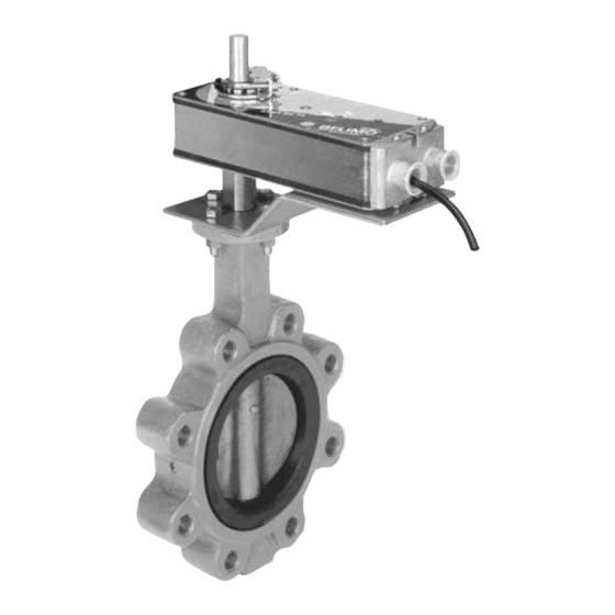
- Page 2 F6/F7…HS/HSU Series Butterfly Valves Resilient Seat, 304 Stainless Disc with AM/AR, GM/GR and AF Series Electronic Actuation • 50 psi bubble tight shut-off (HSU Series) • 200 psi bubble tight shut-off (HS Series) • Long stem design allows for 2” insulation •...
- Page 3 F6/F7...HS/HSU Series Butterfly Valves Mechanical Data, use with pages 4 & 5 F7... Dimensional Data Dimensions in inches. F6... Dimensional Data Dimensions in inches. Ordering Information: Please note that HS series BF valves over 18" and ALL sizes 3-way tee assemblies ordered with Configuration C are special order / custom built and are NOT returnable.
- Page 4 F6…HSU Series Butterfly Valves Resilient Seat, 304 Stainless Disc with AM/AR, GM/GR and AF Series Electronic Actuation Maximum dimensions, measured in inches Close-Off Pressures Non-Fail Safe Fail Safe AM/AR GM/GR 2*GM 2*AF Valve Size D(Max) BHC Holes Lug Bolt (psi) (psi) (psi) (psi)
- Page 5 F7…HSU Series Butterfly Valves Resilient Seat, 304 Stainless Disc with AM/AR, GM/GR and AF Series Electronic Actuation Maximum dimensions, measured in inches Close-Off Pressures Non-Fail Safe Fail Safe AM/AR GM/GR 2*GM 2*AF Valve Size D(Max) BHC Holes Lug Bolt (psi) (psi) (psi) (psi)
- Page 6 F6/F7...HS/HSU Series Butterfly Valves Full Rated and Undercut, Resilient Seat 304 Stainless Disc with Belimo SY Series Electric Actuation • 50 psi bubble tight shut-off 2” to 12” (HSU Series) • 200 psi bubble tight shut-off 2” to 12” (HS Series) •...
- Page 7 F6/F7…HS/HSU Series Butterfly Valves Mechanical Data, use with pages 8 & 9 F6... Dimensional Data Dimensions in inches. Actuation Specifications (see actuator section for details) Type industrial electric Supply Voltages 24 VAC ±10%, 120 VAC ±10% 230 VAC ±10% Control Scheme 2 Position/Floating Point 2-10 VDC, 0-10 VDC 4-20mA, MFT...
- Page 8 4. Dimension “D” allows for actuator removal without the need to remove the valve from the pipe. 5. Belimo SY Series actuators are NEMA 4, 4x rated. F6…HS Series Butterfly Valves Full rated, Resilient Seat 304 Stainless Disc with Belimo SY Series Electric Actuation Maximum dimensions, measured in inches Close-Off...
- Page 9 6. Bolts supplied are for shipping purposes only. Upon installation, replace with an appropriate SAE grade 5 or better hardware. F7…HS Series Butterfly Valves Full rated, Resilient Seat 304 Stainless Disc with Belimo SY Series Electric Actuation Maximum dimensions, measured in inches...
- Page 10 SY…24 Series Non-Spring Return Actuator Technical Data - 24 VAC Application: The SY actuators are NEMA 4, 4x rated and designed to meet the needs of HVAC and Commercial applications. Offered on the HSU and HS butterfly valve series, these actuators are available for on/off and modulating applications.
- Page 11 SY…120 Series Non-Spring Return Actuator Technical Data - 120 VAC Application: The SY actuators are NEMA 4, 4x rated and designed to meet the needs of HVAC and Commercial applications. Offered on the HSU and HS butterfly valve series, these actuators are available for on/off and modulating applications.
- Page 12 SY…230 Series Non-Spring Return Actuator Technical Data - 230 VAC Application: The SY actuators are NEMA 4, 4x rated and designed to meet the needs of HVAC and Commercial applications. Offered on the HSU and HS butterfly valve series, these actuators are available for on/off and modulating applications.
- Page 13 SY… Series Non-Spring Actuator Dimensions SY-1... SY-2~6... SY-9~12... SY-7~8... MODEL DIM A (MAX) Add to Dim A for DIM B DIM C (MAX) DIM D cover removal Inches Inches Inches Inches Inches 6.10 3.94 4.25 SY2~3 10.04 7.48 7.87 12.99 7.87 SY4~6 12.40...
- Page 14 WARNING SY… Series Non-Spring Actuators CAUTION Electrical Travel Adjustment (Factory Pre-set) SY-1 Factory pre-set see chart below. Field adjustable if required INSTALLATION NOTES Auxiliary Switch for Closed Indication Auxiliary Switch for Opened Indication APPLICATION NOTES Factory pre-set and calibrated. Do not adjust - warranty voided WARNING WARNING Clockwise Decrease Closed Angle...
- Page 15 WARNING SYx-SR/MFT Interface Wiring Detail CAUTION WARNING Notes: INSTALLATION NOTES 1. Motor CAMS have been factory calibrated and should not be moved. 2. An adaption must be performed if any limit switch is adjusted. This will calibrate the beginning and end stopping points. Press the adaption button for CAUTION 3 seconds and release.
- Page 16 SYx-P Interface Wiring Detail WARNING Open LED Closed LED Supply Sensitivity switchsetting WARNING is position #3 for factory - SIG default. To widen dead- + IN Sensitivity band, select a higher WARNING number (up to 9). - FB CAUTION + OUT Dip Switch WARNING Notes:...
- Page 17 Wire size vs. length of run for SY Series Actuators...
-
Page 18: Installation Notes
Wiring for Damper Actuators and Control Valves SY Actuator Wiring Diagram, SY1…5-24 – On/Off SY Actuator Wiring Diagram, SY1…5-24 and SY1…12-110 (220) On/Off SY1…12-110 (220) On/Off Hazard Identification INSTALLATION NOTES Warnings and Cautions appear at appropriate sections throughout this manual. Read these carefully. Observe class 1 and class 2 wiring restrictions. -
Page 19: Application Notes
Wiring for Damper Actuators and Control Valves SY Actuator Wiring Diagram, SY1…5-24P and SY1…12-110P (220P) SY Actuator Wiring Diagram, SY1-24P, SY1-110P (220P) Hazard Identification INSTALLATION NOTES Warnings and Cautions appear at appropriate sections throughout this manual. Read these carefully. Observe Class 1 and Class 2 wiring restrictions CAUTION Transformer sizing = SY actuator draw X 1.25 (safety margin) (Ex. - Page 20 Wiring for Damper Actuators and Control Valves SY Actuator Wiring Diagram, SY1…5-24P and SY1…12-110P (220P) SY Actuator Wiring Diagram, SY2...5-24SR/MFT, SY2...12-120SR/MFT (230SR/MFT) Hazard Identification INSTALLATION NOTES Warnings and Cautions appear at appropriate sections throughout this manual. Read these carefully. Observe Class 1 and Class 2 wiring restrictions CAUTION Transformer sizing = SY actuator draw X 1.25 (safety margin) (Ex.
- Page 21 F6/F7... HS/HSU Butterfly Valves SY Actuator Wiring Diagram, SY1…5-24 – Multiple Wiring SY Actuator Wiring Diagram, SY1…5-24 and SY1…12-110 (220) - Multiple Wiring SY1…12-110 (220) – Multiple Wiring Hazard Identification INSTALLATION NOTES Warnings and Cautions appear at appropriate sections throughout this Observe class 1 and class 2 wiring restrictions.
- Page 22 F6/F7... HS/HSU Butterfly Valves SY Actuator Wiring Diagram, SY1…5-24P – Multiple Wiring SY Actuator Wiring Diagram, SY1-24P Hazard Identification Actuator B 24 VAC Transformer Ground Warnings and Cautions appear at appropriate sections throughout this manual. Read these carefully. Power Supply Com Line Volts Power Supply Hot...
- Page 23 F6/F7... HS/HSU Butterfly Valves SY Actuator Wiring Diagram, SY1…5-24P – Multiple Wiring SY Actuator Wiring Diagram, SY1…5-24P – Multiple Wiring SY Actuator Wiring Diagrams, SY2...5-24SR/MFT - Multiple Wiring Hazard Identification Hazard Identification INSTALLATION NOTES INSTALLATION NOTES Warnings and Cautions appear at appropriate Warnings and Cautions appear at appropriate sections throughout this manual.
- Page 24 F6/F7... HS/HSU Butterfly Valves SY Actuator Wiring Diagram, SY1…12-110P, (220P) – Multiple Wiring SY Actuator Wiring Diagrams, SY1-110P (220P) Actuator B Ground Hazard Identification 120 and 230 VAC Warnings and Cautions appear at appropriate N L1 Power Supply Com sections throughout this manual. Read these carefully. H L2 Power Supply Hot CAUTION...
- Page 25 F6/F7... HS/HSU Butterfly Valves SY Actuator Wiring Diagram, SY1…12-110P, (220P) – Multiple Wiring SY Actuator Wiring Diagram, SY2...12-120SR/MFT (230SR/MFT) - Multiple Wiring Hazard Identification INSTALLATION NOTES Warnings and Cautions appear at appropriate sections throughout this manual. Read these carefully. Observe class 1 and class 2 wiring restrictions. CAUTION Indicates a potentially hazardous situation which, if not avoided, may result in minor or moderate injury.
- Page 26 AR Series Non-Spring Return Actuator Technical Data Common Data Actuation Specifications (see actuator section for details) Power consumption 2 W running, 0.2 W holding ARB24-3-5 4 W running, 1.25 W holding ARB24-MFT-5 Type direct coupled electronic Transformer sizing 6 VA, class 2 power source Supply Voltages 24 VAC, ±20% 50/60 Hz Electrical connection...
- Page 27 AR Series Non-Spring Return Actuator Technical Data Actuators: ARB24-MFT-5 Hazard Identification INSTALLATION NOTES Warnings and Cautions appear at appropriate sections throughout this manual. Read these carefully. Actuators may also be powered by 24 VDC. Actuators with plenum rated cable do not have numbers on CAUTION wires;...
- Page 28 GR Series Non-Spring Return Technical Data Common Data Actuation Specifications (see actuator section for details) Transformer sizing 7 VA (class 2 power source) Type direct coupled electronic Power supply 24 VAC ±20% 50/60 Hz 24 VDC ±10% Power consumption 4.5 W running, 2 W holding Supply Voltages 24 VAC, ±20% 50/60 Hz 24 VDC, ±10%...
- Page 29 GR Series Non-Spring Return Technical Data Actuators: GRX24-MFT-7 Hazard Identification INSTALLATION NOTES Warnings and Cautions appear at appropriate sections throughout this manual. Read these carefully. Actuators may also be powered by 24 VDC. Actuators with plenum rated cable do not have numbers on CAUTION wires;...
- Page 30 GR Series Non-Spring Return Technical Data Common Data Actuation Specifications (see actuator section for details) Power supply 24 VAC ±20% 50/60 Hz 24 VDC ±10% Power consumption 4.5 W, 2 W holding Type direct coupled electronic Electrical connection 3 ft, 18 GA appliance cable, Supply Voltages 24 VAC, ±20% 50/60 Hz ½”...
- Page 31 GR Series Non-Spring Return Technical Data Actuators: GRX24-MFT-5 Hazard Identification INSTALLATION NOTES Warnings and Cautions appear at appropriate sections throughout this manual. Read these carefully. Actuators may also be powered by 24 VDC. Actuators with plenum rated cable do not have numbers on CAUTION wires;...
- Page 32 GM Series Non-Spring Return Technical Data Common Data (each actuator) Actuation Specifications (see actuator section for details) Transformer sizing 7 VA (class 2 power source) Type direct coupled electronic Power supply 24 VAC ±20% 50/60 Hz 24 VDC ±10% Power consumption 4.5 W running, 2 W holding Supply Voltages 24 VAC, ±20% 50/60 Hz...
- Page 33 GM Series Non-Spring Return Technical Data Actuators: GMX24-MFT-7 Hazard Identification INSTALLATION NOTES Warnings and Cautions appear at appropriate sections throughout this manual. Read these carefully. Actuators may also be powered by 24 VDC. Actuators with plenum rated cable do not have numbers on CAUTION wires;...
- Page 34 GM Series Non-Spring Return Technical Data Common Data Actuation Specifications (see actuator section for details) Power supply 24 VAC ±20% 50/60 Hz 24 VDC ±10% Type direct coupled electronic Power consumption 4.5 W, 2 W holding Electrical connection 3 ft, 18 GA appliance cable, Supply Voltages 24 VAC, ±20% 50/60 Hz ½”...
- Page 35 GM Series Non-Spring Return Technical Data Actuators: GMX24-MFTX1 Hazard Identification INSTALLATION NOTES Warnings and Cautions appear at appropriate sections throughout this manual. Read these carefully. Actuators may also be powered by 24 VDC. Actuators with plenum rated cable do not have numbers on CAUTION wires;...
- Page 36 AF Series Spring Return Actuator Technical Data Proportional Control, 24 VAC/DC Power Actuation Specifications J AF24-MFT-S US (AF24-MFT US with built-in auxiliary switches) (see actuator section for details) J AF24-MFT95 US Type direct coupled electronic 0-135 W Control signal: Supply Voltages 24 VAC, ±10% Feedback output: 2 to 10 VDC, 0.5 mA max...
- Page 37 Position feedback cannot be used with a Triac sink controller. VDC/4-20 mA The actuator internal common reference is not compatible. IN4004 or IN4007 diode. (IN4007 supplied, Belimo part WARNING number 40155) Live Electrical Components! During installation, testing, servicing and troubleshooting of this product, it maybe necessary to work with live electrical components.
-
Page 38: Installation Recommendations
Installation Recommendations F6…, F7… Series Butterfly Valves HS (U) Series Butterfly Valves: Storage of BF Valve assemblies Make sure the flange faces are clean and free of rust, Assemblies must be stored indoors, protected from scale and debris to prevent damage to the liner face. the elements. - Page 39 Installation Recommendations F6…, F7… Series Butterfly Valves Flange Bolting Recommendations Flange Detail for Ansi B16.5 Pipe Flanges Flanges Drilling Bolting Nominal Flange Flange Diameter of Diameter of Number Diameter Pipe Size Diameter Thickness Bolt Circle Bolt Holes of Bolts of Bolts 2”...
- Page 40 Installation Recommendations F6HS(U)…, F7HS(U)… Series Butterfly Valves Note: Actuator must evenly to assure uniform compression. In assembling flange be mounted at or joints, the resilient seating surface shall be uniformly com- above pipe centerline pressed to the proper minimum dimension as shown in the detail drawing below.
-
Page 41: Maintenance Instructions
Installation Recommendations F6HS(U)…, F7HS(U)… Series Butterfly Valves Incorrect Correct Disc in closed position. No flange gaskets used. Gasket Gaskets installed between Disc in the “almost closed” valve and mating flanges. position. Figure 2: Centering and Flanging of Valve Figure 3: Flange Bolt Tightening Sequence Incorrect Correct Pipe Flanges mis-aligned. - Page 42 Notes/Work Pad...
- Page 43 Belimo Platinum Distributors ACR Supply Company Inc. Industrial Controls Distributors LLC Airex 2719 Hillsborough Road 1776 Bloomsbury Avenue C - 5 Sandhill Court Brampton, ON, L6T 5J5 Durham, NC 27705 Wanamassa, NJ 07712 Phone: 919-286-2228 Phone: 800-631-2112 Phone: 905-790-8667 With branches in With branches in NC Baymar Supply Co.
- Page 44 United States, Canada, (203) 791-9915 Toll Free: (800) 987-9042 and Latin America. Fax: (800) 228-8283 (775) 857-4243 It is part of Belimo Holding, (800- ACTUATE ) Fax: (800) 987-8875 a publicly held company in (775) 857-4255 (203) 791-9919 Switzerland with business...
Need help?
Do you have a question about the F6 HS Series and is the answer not in the manual?
Questions and answers