Advertisement
Quick Links
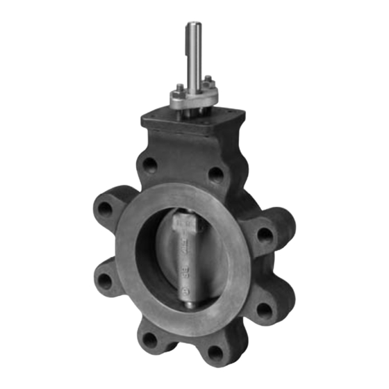
F6 Series 2-Way, ANSI Class 300 Butterfl y Valve
Reinforced Tefl on Seat, 316 Stainless Disc
Technical Data
Service
chilled, hot water, 60% glycol,
steam to 50 psi
Flow characteristic
modifi ed equal percentage, unidirectional
Controllable fl ow range
82°
Sizes
2" to 24"
Type of end fi tting
ANSI 300 fl anges
Materials
Body
carbon steel full lug
Disc
316 stainless steel
Seat
RPTFE
Shaft
17-4 PH stainless
Gland seal
PTFE
Bushings
glass backed PTFE
Media temperature range -20°F to 400°F [-30°C to 204°C]
Body pressure rating
ANSI Class 300
Close-off pressure
740 psi
Rangeability
100:1 (for 30 deg to 70 deg range)
Maximum velocity
32 FPS
Leakage
bubble tight
Valve
Size
102
F650-300SHP
2"
146
F665-300SHP
2½"
228
F680-300SHP
3"
451
F6100-300SHP
4"
714
F6125-300SHP
5"
1103
F6150-300SHP
6"
2064
F6200-300SHP
8"
3517
F6250-300SHP
10"
4837
F6300-300SHP
12"
6857
F6350-300SHP
14"
9287
F6400-300SHP
16"
11400
F6450-300SHP
18"
14420
F6500-300SHP
20"
22050
F6600-300SHP
24"
800-543-9038 USA
30
C
10°
20°
v
1.50
6.10
2.20
8.80
3.40
14
6.80
27
11
43
17
66
31
124
53
211
73
290
90
392
132
531
171
684
207
828
315
1260
866-805-7089 CANADA
• Bubble tight shut-off to ANSI Class 300 Standards
• Long stem design allows for 2" insulation minimum
• Valve Face-to-face dimensions comply with API 609 & MSS-SP-68
• Designed to be installed between ASME/ANSI B16.5 Flanges
• Completely assembled and tested, ready for installation
Application
These valves are designed to meet the needs of HVAC and Commercial
applications requiring positive shut-off for liquids at higher pressures and
temperatures. Typical applications include chiller isolation, cooling tower
isolation, change-over systems, large air handler coil control, bypass and
process control applications. The large C
control valve solution for larger fl ow applications.
Dead End Service
Utilizes larger retainer ring set screws to allow the valve to be placed at the end of
the line without a down stream fl ange in either fl ow direction while still holding full
pressure.
2-way Valves
Valve
Nominal
Size
C v
C v
Inches
ANSI 300 2-way
90°
60°
102
56
2
F650-300SHP
146
80
2½
F665-300SHP
228
125
3
F680-300SHP
451
248
4
F6100-300SHP
714
392
5
F6125-300SHP
1103
607
6
F6150-300SHP
2064
1135
8
F6200-300SHP
3517
1934
10
F6250-300SHP
4837
2660
12
F6300-300SHP
6857
3592
14*
F6350-300SHP
9287
4865
16*
F6400-300SHP
11400
6270
18*
F6450-300SHP
14420
7590
20*
F6500-300SHP
22050 11550
24*
F6600-300SHP
30°
40°
50°
14
26
39
20
37
55
32
57
87
63
114
171
100
180
271
154
278
419
289
520
784
492
886
1336
677
1219
1838
914
1646
2481
1230
2229
3361
1596
3873
4332
1932
3478
5244
2940
5292
7890
values provide for an economical
v
Suitable Actuators
Fail-Safe
Non Fail-Safe
Spring
Return
150
300
150
300
MOD
60°
70°
80°
56
77
99
80
110
142
125
171
221
248
338
437
393
536
693
607
827
1070
1135
1548
2002
1934
2638
3411
2660
3628
4692
3592
4898
6530
4865
6634
8845
6270
8550
11270
7590
10350
13800
11550
15750
21000
203-791-8396 LATIN AMERICA / CARIBBEAN
Electronic
150
300
ON/OFF
90°
102
146
228
451
714
1103
2064
3517
4837
6857
9287
11400
14420
22050
Advertisement

Related Manuals for Belimo F6 Series


Summary of Contents for Belimo F6 Series
- Page 1 F6 Series 2-Way, ANSI Class 300 Butterfl y Valve Reinforced Tefl on Seat, 316 Stainless Disc • Bubble tight shut-off to ANSI Class 300 Standards • Long stem design allows for 2” insulation minimum • Valve Face-to-face dimensions comply with API 609 & MSS-SP-68 •...
- Page 2 F6 Series 2-Way, ANSI Class 300 Butterfl y Valve Reinforced Tefl on Seat, 316 Stainless Disc Maximum Dimensions (Inches) Valve Size 90° D(Max) No. of Holes Lug Bolt Actuator Close-Off (PSI F650-300SHP 2” 1.75 9.00 9.00 19.50 5.00 5/8-11 UNC F665-300SHP 2½”...
- Page 3 F7 Series 3-Way, ANSI Class 300 Butterfl y Valve Reinforced Tefl on Seat, 316 Stainless Disc • Bubble tight shut-off to ANSI Class 300 Standards • Long stem design allows for 2” insulation minimum • Valve Face-to-face dimensions comply with API 609 & MSS-SP-68 •...
- Page 4 F7 Series 3-Way, ANSI Class 300 Butterfl y Valve Reinforced Tefl on Seat, 316 Stainless Disc Maximum Dimensions (Inches) Valve Size 90° D(Max) No. of Holes Lug Bolt Actuator Close-Off (PSI) F750-300SHP 2” 5.00 6.75 6.75 15.50 5.00 5/8-11 UNC F765-300SHP 2½”...
- Page 5 The SY actuators are NEMA 4X rated and designed to meet the needs of HVAC and Commercial applications. Offered on Belimo standard and high performance valve series, these actuators are available for on/off and modulating applications. Depending on the application, they are available in 24 VAC/ VDC, 120 VAC and 230 VAC.
- Page 6 The SY actuators are NEMA 4X rated and designed to meet the needs of HVAC and Commercial applications. Offered on Belimo standard and high performance valve series, these actuators are available for on/off and modulating applications. Depending on the application, they are available in 24 VAC/ VDC, 120 VAC and 230 VAC.
- Page 7 The SY actuators are NEMA 4X rated and designed to meet the needs of HVAC and Commercial applications. Offered on Belimo standard and high performance valve series, these actuators are available for on/off and modulating applications. Depending on the application, they are available in 24 VAC/ VDC, 120 VAC and 230 VAC.
- Page 8 SY... Series Non-Spring Return Actuator Dimensions SY-2~6... SY-9~12... SY-7~8... Add to Dim A for MODEL DIM A (MAX) cover removal DIM B DIM C (MAX) DIM D Inches [mm] Inches [mm] Inches [mm] Inches [mm] Inches [mm] SY4~6 12.40 [315] 8.86 [225] 9.21 [234] 14.96 [380]...
- Page 9 Butterfly Valve Actuators Power Supply 24 VAC/VDC Single Phase Speed Current Draw Current Draw Model # Torque Override Weight 50 Hz/60 Hz (50 Hz) (60 Hz) (50 Hz) (60 Hz) (50 Hz) (60 Hz) PRBUP-3-T* 1400 in-lbs/ 160 Nm 35 seconds 0.8 A 0.8 A Manual override crank...
- Page 10 Butterfly Valve Actuators Power Supply 24 VAC/VDC Single Phase Speed Current Draw Current Draw Model # Torque Override Weight 50 Hz/60 Hz (50 Hz) (60 Hz) (50 Hz) (60 Hz) (50 Hz) (60 Hz) PRXUP-MFT-T* 1400 in-lbs/160 Nm 30-120 sec. 0.9 A 0.9 A Manual override crank...
-
Page 11: Installation Notes
Wiring for Control Valves On/Off, 24V, 120/230V SY Actuator Wiring Diagram, SY1…5-24V – On/Off SY1…12-120V or 230V On/Off Hazard Identification INSTALLATION NOTES Warnings and Cautions appear at appropriate sections throughout this manual. Read these carefully. Observe class 1 and class 2 wiring restrictions. CAUTION Indicates a potentially hazardous situation which, if not avoided, Transformer sizing = SY actuator draw X 1.25 (safety margin) - Page 12 Wiring for Control Valves Proportional, 24V, 120/230V Actuator: SY2…5-24MFT SY2...12-120MFT SY2...12-230MFT Hazard Identification INSTALLATION NOTES this manual. Read these carefully. CAUTION Indicates a potentially hazardous situation which, if not avoided, may result in minor or moderate injury. It may also be used to alert against unsafe practices.
- Page 13 Wiring for Control Valves On/Off, 24V, 110/120/230V SY Actuator Wiring Diagram, SY1…5-24 – Multiple Wiring SY1…12-110 (220) – Multiple Wiring Hazard Identification INSTALLATION NOTES Warnings and Cautions appear at appropriate sections throughout this Observe class 1 and class 2 wiring restrictions. manual.
-
Page 14: Application Notes
Wiring for Control Valves Proportional, Multiple Wiring, 24V Actuators: SY2...5-24MFT Hazard Identification INSTALLATION NOTES Warnings and Cautions appear at appropriate sections throughout this manual. Read these carefully. Observe class 1 and class 2 wiring restrictions. CAUTION Transformer sizing = SY actuator draw X 1.25 (safety margin) Indicates a potentially hazardous situation which, if (Ex. - Page 15 Wiring for Control Valves Proportional, Multiple Wiring, 120/230V Actuators: SY2...12-120MFT SY2...12-230MFT Hazard Identification INSTALLATION NOTES Warnings and Cautions appear at appropriate sections throughout this manual. Read these carefully. Observe class 1 and class 2 wiring restrictions. CAUTION Indicates a potentially hazardous situation which, if not avoided, may result in minor or moderate injury.
-
Page 16: Technical Data
AFBUP(-S)-X1, AFXUP(-S)-X1 Actuators, On/Off Models AFBUP-X1 AFBUP-S-X1 AFXUP-X1 AFXUP-S-X1 Technical Data Power supply 24...240 VAC -20% / +10%, 50/60 Hz 24...125 VDC ±10% Power consumption running holding 3.5 W Transformer sizing 7 VA @ 24 VAC (class 2 power source) 8.5 VA @ 120 VAC 18 VA @ 240 VAC Electrical connection... - Page 17 AFBUP(-S)-X1, AFXUP(-S)-X1 Actuators, On/Off Wiring Diagrams Provide overload protection and disconnect as required. CAUTION Equipment Damage! Actuators may be connected in parallel. Power consumption and input impedance must be observed. No ground connection is required. For end position indication, interlock control, fan startup, etc., AFBUP-S-X1 and AFXUP-S-X1 incorporates two built-in auxiliary switches: 2 x SPDT, 3A (0.5A) @250 VAC, UL Approved, one switch is fi...
- Page 18 AF Actuators, Multi-Function Technology Models AFX24-MFT-X1 AFX24-MFT-S-X1 w/built-in Aux. Switches 2*AFX24-MFT-X1 2*AFX24-MFT-S-X1 Technical Data Power supply 24 VAC, +/- 20%, 50/60 Hz 24 VDC, +20% / -10% Power running 7.5 W consumption holding 3 W Transformer sizing 10 VA (Class 2 power source) Electrical connection AFX...
- Page 19 AF Actuators, Multi-Function Technology Wiring Diagrams Actuators may also be powered by 24 VDC. IN4004 or IN4007 diode (IN4007 supplied, Belimo part number 40155). Triac A and B can also be contact closures. Control signal may be pulsed from either the Hot (Source) or Common (Sink) 24 VAC line.
- Page 20 DKRX24-3-T, DKRX(B)24-3-T N4(H) NEMA 2/NEMA 4 Actuators, On/Off, Floating Point Models DKRX24-3-T w/terminal block DKRX24-3-T N4 w/terminal block DKRB24-3-T N4H w/heater Technical Data Control on/off, fl oating point Power supply 24 VAC ± 20/-10% 50/60 Hz Power consumption running 12W / heater 33W holding 3W Transformer sizing 21 VA (class 2 power source) / heater 36 VA...
-
Page 21: Electrical Installation
2.50 mm <100 m <20 m 1 m (L ) + 19 m (L = Belimo connecting cable, 1 m (4 x 0.75 mm = Customer cable = Actuator = Maximum cable length = Control unit = Belimo connecting cable, 1 m (4 x 0.75 mm m m ) ...3... - Page 22 DKRX24-MFT-T, DKRX(B)24-MFT-T N4(H) NEMA 2/NEMA 4 Actuators, Multi-Function Technology Models DKRX24-MFT-T w/terminal block DKRX24-MFT-T N4 w/terminal block DKRB24-MFT-T N4H w/heater Technical Data Control 2 to 10 VDC, 4 to 20 mA (default) variable (VDC, fl oating point, on/off) Power supply 24 VAC ±...
- Page 23 Triac sink controller. The actuator internal common reference is not compatible. IN4004 or IN4007 diode. (IN4007 supplied, Belimo part number 40155). On/Off control The ZG-R01 500 Ω resistor converts the 4 to 20 mA control signal to 24 VAC Transformer 2 to 10 VDC, up to 2 actuators may be connected in parallel.
- Page 24 DRCX24-3-T, DRCX(B)24-3-T N4(H) NEMA 2/NEMA 4 Actuators, On/Off, Floating Point Models DRCX24-3-T w/terminal block DRCX24-3-T N4 w/terminal block DRCB24-3-T N4H w/heater Technical Data Control on/off, fl oating point Power supply 24 VAC ± 20/-10% 50/60 Hz 24 VDC ± 10% Power consumption running 9W / heater 29W holding 2W...
- Page 25 DRCX24-3-T, DRCX(B)24-3-T N4(H) NEMA 2/NEMA 4 Actuators, On/Off, Floating Point Wiring Diagrams 24 VAC Transformer Blk (1) Common – Line Volts CAUTION Equipment damage! Red (2) + Actuators may be connected in parallel. Power consumption and input impedance must be observed. a open Wht (3) + a closed...
- Page 26 DRX24-MFT-T, DRX24-MFT-T N4, DRCX24-MFT-T, DRCX(B)24-MFT-T N4(H) NEMA 2/NEMA 4 Actuators, Multi-Function Technology Models DRX24-MFT-T w/terminal block DRX24-MFT-T N4 w/terminal block DRCX24-MFT-T w/terminal block DRCX24-MFT-T N4 w/terminal block DRCB24-MFT-T N4H w/heater Technical Data Control 2 to 10 VDC, 4 to 20 mA (default) variable (VDC, fl...
- Page 27 Hot connection of the controller. Position feedback cannot be used with a Triac sink controller. The actuator internal On/Off Control common reference is not compatible. IN4004 or IN4007 diode. (IN4007 supplied, Belimo part number 40155). 24 VAC Transformer Blk (1) – Common Line...
- Page 28 GK Actuators, On/Off, Floating Point Models GKRB24-3-X1 GKRB24-3-5 GKB24-3-X1 Technical Data Power supply 24VAC ±20% 50/60Hz Power consumption 12W (3W) Transformer sizing 21VA (class 2 power source) Electrical connection 18 GA plenum rated cable ½" conduit connector protected NEMA 2 (IP54) 3 ft [1m] 10 ft [3m] 16 ft [5m] Overload protection electronic throughout 0 to 95 rotation...
-
Page 29: On/Off Control
= Control unit 2.50 mm <100 m <20 m 1 m (L ) + 19 m (L = Belimo connecting cable, 1 m (4 x 0.75 mm Blk (1) Common = Customer cable – = Actuator Line = Maximum cable length... - Page 30 GK Actuators, Multi-Function Technology Models GKRX24-MFT-X1 GKX24-MFT-X1 Technical Data GKX24-MFT-X1 Power supply 24VAC ±20% 50/60Hz 24VDC ±10% Power consumption 12W (3W) Transformer sizing 21VA (class 2 power source) Electrical connection 18 GA plenum rated cable ½" conduit connector protected NEMA 2 (IP54) 3 ft [1m] 10 ft [3m] 16 ft [5m] Overload protection electronic throughout 0 to 95 rotation...
- Page 31 GK Actuators, Multi-Function Technology Wiring Diagrams Provide overload protection and disconnect as required. Actuators may also be powered by 24 VDC. Position feedback cannot be used with Triac sink controller. The actuator internal common reference is not compatible. Control signal may be pulsed from either the Hot (source) or the Common (sink) 24 VAC line.
- Page 32 AM/AR Series Actuators, On/Off, Floating Point Models AMB24-3-X1 ARB24-3-X1 ARB24-3-5 Technical Data Power supply 24 VAC ± 20% 50/60 Hz 24 VDC ± 10% Power consumption running 2.0 W holding 0.2 W Transformer sizing 5.5 VA (class 2 power source) Electrical connection 3 ft, 18 GA plenum rated cable ½”...
- Page 33 AM/AR Series Actuators, On/Off, Floating Point Wiring Diagrams 24 VAC Transformer Blk (1) Common Line CAUTION Equipment damage! Volts Red (2) + Actuators may be connected in parallel. Power consumption and input impedance must be observed. Wht (3) + a open a closed Actuators may also be powered by 24 VDC.
- Page 34 AM/AR Series Actuators, Multi-Function Technology Models AMX24-MFT-X1 ARX24-MFT-X1 ARB24-MFT-5 Technical Data Power supply 24 VAC ± 20% 50/60 Hz 24 VDC ± 10% Power running 4 W consumption holding 1.25 W Transformer sizing 6 VA (class 2 power source) Electrical connection 3 ft [1m], 10 ft [3m], 16 ft [5m] 18 GA plenum rated cable ½”...
-
Page 35: Floating Point
AM/AR Series Actuators, Multi-Function Technology Wiring Diagrams 24 VAC/DC Transformer Common Line Volts Actuators may also be powered by 24 VDC. Position feedback cannot be used with Triac sink controller. (–) Position Y Input The actuator internal common reference is not compatible. Feedback VDC (+) U Output Control signal may be pulsed from either the Hot (source) - Page 36 GM/GR Actuators, On/Off, Floating Point Models GMB24-3-X1 GRB24-3-X1 GRB24-3-5 GRB24-3-7 Technical Data Power supply 24 VAC ± 20% 50/60 Hz 24 VDC ± 10% Power consumption running 4.0 W holding 2 W Transformer sizing 6 VA (class 2 power source) Electrical connection 3 ft, 18 GA appliance cable, 1/2”...
- Page 37 GM/GR Actuators, On/Off, Floating Point Wiring Diagrams CAUTION Equipment damage! Actuators may be connected in parallel. Power consumption and input impedance must be observed. Actuators may also be powered by 24 VDC. Actuators with plenum rated cable do not have numbers on wires; use color codes instead.
- Page 38 GM/GR Actuators, Multi-Function Technology Models GMX24-MFT-X1 GRX24-MFT-X1 GRB24-MFT-5 GRX24-MFT-7 Technical Data Power supply 24 VAC ± 20% 50/60 Hz 24 VDC ± 10% Power consumption running 4.5 W holding 2 W Transformer sizing 7 VA (class 2 power source) Electrical connection 3 ft, 18 GA appliance cable, 1/2”...
- Page 39 GM/GR Actuators, Multi-Function Technology Wiring Diagrams 24 VAC Transformer Common Line Volts + Hot Actuators may also be powered by 24 VDC. 500Ω Ω 1/4 watt Actuators with plenum rated cable do not have numbers on wires; use (–) Control Signal 4 to 20 mA color coded instead.
- Page 40 GRCX(B)24-3-T N4(H) NEMA 4 Actuators, On/Off, Floating Point Models GRCX24-3-T N4 w/terminal block GRCB24-3-T N4H w/heater Technical Data Control on/off, fl oating point Power supply 24 VAC ± 20% 50/60 Hz 24 VDC ± 10% Power consumption running 8W / heater 29W holding 2.5W Transformer sizing 11 VA (class 2 power source) / heater 26 VA...
- Page 41 GRCX(B)24-3-T N4(H) NEMA 4 Actuators, On/Off, Floating Point Wiring Diagrams CAUTION Equipment damage! Actuators may be connected in parallel. Power consumption and input impedance must be observed. Actuators may also be powered by 24 VDC. Actuators with plenum rated cable do not have numbers on wires; use color codes instead.
- Page 42 GRX(B)24-MFT-T N4(H) NEMA 4 Actuators, Multi-Function Technology Models GRX24-MFT-T N4 w/terminal block GRB24-MFT-T N4H w/heater Technical Data Control 2 to 10 VDC, 4 to 20 mA (default) variable (VDC, fl oating point, on/off) Power supply 24 VAC ± 20% 50/60 Hz 24 VDC ±...
- Page 43 Triac sink controller. The actuator internal common reference is not compatible. Wht (3) Y Input IN4004 or IN4007 diode. (IN4007 supplied, Belimo part number 40155). (–) 2 to 10 VDC (5) U Output 2 to 10V Feedback Signal The ZG-R01 500 Ω...
- Page 44 GMCX(B)24-3-T-X1 N4(H) NEMA 4 Actuators, On/Off, Floating Point Models GMCX24-3-T-X1 N4 w/terminal block GMCB24-3-T-X1 N4H w/heater Technical Data Control on/off, fl oating point Power supply 24 VAC ± 20% 50/60 Hz 24 VDC ± 10% Power consumption running 8W / heater 28W holding 2.5W Transformer sizing 11 VA (class 2 power source) / heater 26 VA...
- Page 45 GMCX(B)24-3-T-X1 N4(H) NEMA 4 Actuators, On/Off, Floating Point Wiring Diagrams CAUTION Equipment damage! Actuators may be connected in parallel. Power consumption and input impedance must be observed. Actuators may also be powered by 24 VDC. Actuators with plenum rated cable do not have numbers on wires; use color codes instead.
- Page 46 GMX(B)24-MFT-T N4(H) NEMA 4 Actuators, Multi-Function Technology Models GMX24-MFT-T-X1 N4 w/terminal block GMB24-MFT-T-X1 N4H w/heater Technical Data Control 2 to 10 VDC, 4 to 20 mA (default) variable (VDC, fl oating point, on/off) Power supply 24 VAC ± 20% 50/60 Hz 24 VDC ±...
- Page 47 GMX(B)24-MFT-T N4(H) NEMA 4 Actuators, Multi-Function Technology Contact closures A & B also can be triacs. A & B should both be closed for triac source and open for triac sink. For triac sink the common connection from the actuator must be connected to the hot connection of the controller.
- Page 48 PRBUP-MFT-T Modulating, Non-Spring Return, 24-240 V, NEMA 4X with BACnet Application PR Series valve actuators are designed with an integrated linkage and visual position indicators. For outdoor applications, the installed valve must be mounted with the actuator at or above horizontal. For indoor applications the actuator can be in any location including directly under the valve.
- Page 49 PRBUP-MFT-T Modulating, Non-Spring Return, 24-240 V, NEMA 4X with BACnet Wiring Diagrams Meets cULus requirements without the need of an electrical ground connection. 24 to 240 VAC Universal Power Supply (UP) models can be supplied with 24 VAC up to Common 240 VAC, or 24 VDC up to 240 VDC.
- Page 50 PRBUP-MFT-T Modulating, Non-Spring Return, 24-240 V, NEMA 4X with BACnet T1 Com T2 Com Temperature Sensors 0˚ to 90˚ default 85˚ Auxiliary Switches 800-543-9038 USA 866-805-7089 CANADA 203-791-8396 LATIN AMERICA / CARIBBEAN...
- Page 51 PRXUP-3-T On/Off, Floating Point, Non-Spring Return, 24-240 V, NEMA 4X Application PR Series valve actuators are designed with an integrated linkage and visual position indicators. For outdoor applications, the installed valve must be mounted with the actuator at or above horizontal. For indoor applications the actuator can be in any location including directly under the valve.
- Page 52 PRXUP-3-T On/Off, Floating Point, Non-Spring Return, 24-240 V, NEMA 4X Wiring Diagrams Meets cULus requirements without the need of an electrical ground connection. 24 to 240 VAC Universal Power Supply (UP) models can be supplied with 24 VAC up to Common 240 VAC, or 24 VDC up to 125 VDC.
- Page 53 PRXUP-MFT-T Modulating, Non-Spring Return, 24-240 V, NEMA 4X with BACnet Application PR Series valve actuators are designed with an integrated linkage and visual position indicators. For outdoor applications, the installed valve must be mounted with the actuator at or above horizontal. For indoor applications the actuator can be in any location including directly under the valve.
- Page 54 PRXUP-MFT-T Modulating, Non-Spring Return, 24-240 V, NEMA 4X with BACnet Wiring Diagrams Meets cULus requirements without the need of an electrical ground connection. 24 to 240 VAC Universal Power Supply (UP) models can be supplied with 24 VAC up to Common 240 VAC, or 24 VDC up to 240 VDC.
- Page 55 PRXUP-MFT-T Modulating, Non-Spring Return, 24-240 V, NEMA 4X with BACnet T1 Com T2 Com Temperature Sensors 0˚ to 90˚ default 85˚ Auxiliary Switches 800-543-9038 USA 866-805-7089 CANADA 203-791-8396 LATIN AMERICA / CARIBBEAN...
- Page 56 PRBUP-3-T On/Off, Floating Point, Non-Spring Return, 24-240 V, NEMA 4X Application PR Series valve actuators are designed with an integrated linkage and visual position indicators. For outdoor applications, the installed valve must be mounted with the actuator at or above horizontal. For indoor applications the actuator can be in any location including directly under the valve.
- Page 57 PRBUP-3-T On/Off, Floating Point, Non-Spring Return, 24-240 V, NEMA 4X Wiring Diagrams Meets cULus requirements without the need of an electrical ground connection. 24 to 240 VAC Universal Power Supply (UP) models can be supplied with 24 VAC up to Common 240 VAC, or 24 VDC up to 125 VDC.
- Page 58 GRB120-3-5-14 On/Off Floating Point, Non-Spring Return, 110 V Technical Data 303843 Power Supply 100-240 VAC ± 20%, 50/60 Hz Power Consumption Running 4 W Power Consumption Holding 2 W Transformer Sizing 7 VA @ 24 VAC (class 2 power source) Electrical Connection 18 GA applicance rated cable with 1/2”...
- Page 59 GRB120-3-5-14 On/Off Floating Point, Non-Spring Return, 110 V Wiring Diagrams INSTALLATION NOTES Line Actuators with appliance cables are numbered. Blu (1) Common Volts Brn (2) Load Provide overload protection and disconnect as required. Actuators may be connected in parallel if not mechanically linked. Power Wht (3) Load consumption and input impedance must be observed.
Need help?
Do you have a question about the F6 Series and is the answer not in the manual?
Questions and answers