Advertisement
BUTTERFLY VALVES
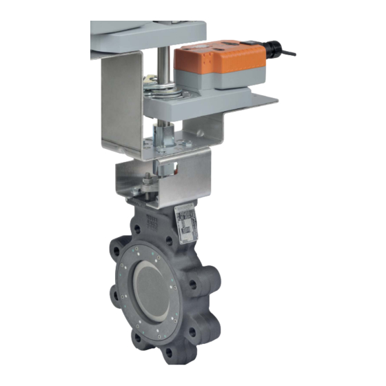
SHP SERIES
High Performance for a Wide
Range of Applications
• Advanced
d seat and disc design provides zero
percent le
eakage capability at each valve's
rated tem
mperature/pressure while maintaining
a low sea
ating torque.
• Stainless
s steel disc and shaft on SHP series
are stan
ndard for superior durability and long
lasting
operation.
Advertisement
Table of Contents

Related Manuals for Belimo SHP Series


Summary of Contents for Belimo SHP Series
- Page 1 • Stainless s steel disc and shaft on SHP series are stan ndard for superior durability and long lasting operation.
- Page 2 Butterfl y Valve Nomenclature -150SHP Valve Valve Size Trim Material Actuator Type Power Supply Control -S = Built-in F6 = 2-way 50 = 2” -150SHP = ANSI Class 150, Non-Spring Return -24 = 24 VAC/DC -3-X1 = On/Off, Stainless Disc, Steel Lug Floating Point Auxiliary Switch F7 = 3-way...
- Page 3 Control Valve Product Range High Performance Butterfl y Valve Product Range Suitable Actuators 2-way Valves Valve Spring Electronic Nominal Type Non-Spring Return Return Fail-Safe Size ANSI 150 ANSI 300 Inches 150 300 150 300 150 300 150 300 90° 60° 2-way 2-way F650-150SHP...
-
Page 4: Features And Benefits
SHP… Series High Performance Butterfl y Valves Valve Design Features • Unique seat and disc design provides Bi-Directional bubble tight shutoff at Belimo SHP... Series Butterfl y Valves rated pressure/temperatures • The Soft Seat design creates a self-energized seal in vacuum-to-low... - Page 5 SHP Series Butterfl y Valves Average Assembly Weights ACTUATOR NON-SPRING RETURN SPRING RETURN ELECTRONIC FAIL-SAFE Size Valve Max GPM GMB(X) 2*GMB(X) 2*AF 2*GK 2” F650-150SHP 24 lbs. 2” F650-150SHP 18 lbs. 19 lbs. 2½” F665-150SHP 24 lbs. 2½” F665-150SHP 18 lbs 19 lbs.
- Page 6 SHP Series Butterfl y Valves with Industrial Actuation ACTUATOR NON-SPRING RETURN Size Valve Model SY2-110 SY3-110 SY4-110 SY5-110 SY7-110 SY8-110 SY9-110 SY10-110 SY11-110 SY-12-110 2” F650-150SHP 39 lbs. 2½” F665-150SHP 39 lbs. 3” F680-150SHP 41 lbs. 4” F6100-150SHP 1253 53 lbs.
- Page 7 SHP Series Butterfl y Valves with Industrial Actuation Average Assembly Weights ACTUATOR NON-SPRING RETURN Size Valve Model Max GPM SY2-110 SY3-110 SY4-110 SY5-110 SY7-110 SY8-110 SY9-110 SY10-110 SY11-110 2” F650-300SHP 39 lbs. 2½” F665-300SHP 39 lbs. 3” F680-300SHP 45 lbs.
- Page 8 SHP Series Butterfl y Valves with Industrial Actuation Average Assembly Weights ACTUATOR NON-SPRING RETURN Size Valve Model SY2-110 SY3-110 SY4-110 SY5-110 SY7-110 SY8-110 SY9-110 SY10-110 SY11-110 SY-12-110 2” F750-300SHP 104 lbs. 2” F750-300SHP 104 lbs 2½” F765-300SHP 124 lbs. 2½”...
- Page 9 3. The Slave Valve may also have an actuator if required (Direct Coupled). 6. All 3-way assemblies are designed for 90 degree actuator rotation. Flow in Std Weight Pipe (Fluid Velocity in GPM). Use with SHP Series BF Valves. SIZE...
-
Page 10: Features & Benefits
Features / Benefi ts Butterfl y Valves SY Series Actuators Belimo’s SY series electric actuators have been designed to mate with our HD(U), Grooved and SHP… series butterfly valves and other quarter turn valve applications. The patented gear drive mechanism provides for efficient, smooth operation while allowing easy manual override at any time. - Page 11 SY... Series Non-Spring Return Actuator Dimensions SY-1... SY-2~6... SY-9~12... SY-7~8... Add to Dim A for MODEL DIM A (MAX) cover removal DIM B DIM C (MAX) DIM D Inches [mm] Inches [mm] Inches [mm] Inches [mm] Inches [mm] 6.10 [155] 3.94 [100] 4.25 [108] SY2~3...
- Page 12 Wire Size vs. Length of Run for SY Series Actuators 800-543-9038 USA 866-805-7089 CANADA 203-791-8396 LATIN AMERICA / CARIBBEAN...
- Page 13 Butterfl y Valve SY Actuators Power Supply 24 VAC/VDC Single Phase Speed Current Draw Current Draw Model Torque Override Weight 50 Hz/60 Hz (50 Hz) (60 Hz) (50 Hz) (60 Hz) (50 Hz) (60 Hz) 8 mm Wrench SY1-24 310 in-lbs/ 35 Nm 20 seconds 1.6 A 1.7 A...
- Page 14 Butterfl y Valve SY Actuators Power Supply 24 VAC/VDC Single Phase Speed Current Draw Current Draw Model Torque Override Weight 50 Hz/60 Hz (50 Hz) (60 Hz) (50 Hz) (60 Hz) (50 Hz) (60 Hz) 8 mm Wrench SY1-24P 310 in-lbs/ 35 Nm 15 seconds 2.0 A 2.0 A...
-
Page 15: Installation Notes
Interface Wiring Detail SYx-MFT, 24V, 120/230V Actuators: SYx-MFT Notes: INSTALLATION NOTES 1. Motor CAMS have been factory calibrated and should not be moved. 2. An adaption must be performed if any limit switch is adjusted. This will calibrate the beginning and end stopping points. Press the adaption CAUTION button for 3 seconds and release. - Page 16 Interface Wiring Detail SYx-P LED Open LED Close N Power Supply (4) Sensitivity switch s e s tting + Power Supply (5) is position #3 for factory Control Signal (6) default. To T T widen dead- Control Signal (7) band, select a higher number (up to 9).
- Page 17 SY... Series Non-Spring Return Actuator CAUTION Electrical Travel Adjustment (Factory Pre-set) SY-1 Factory pre-set see chart below. Field adjustable if required Auxiliary Switch for Closed Indication Auxiliary Switch for Opened Indication Factory pre-set and calibrated. Do not adjust - warranty voided Clockwise Decrease Closed Angle “CLOSE”...
- Page 18 Wiring for Control Valves On/Off, 24V, 120/230V SY Actuator Wiring Diagram, SY1…5-24V – On/Off SY1…12-120V or 230V On/Off Hazard Identification INSTALLATION NOTES Warnings and Cautions appear at appropriate sections throughout this manual. Read these carefully. Observe class 1 and class 2 wiring restrictions. CAUTION Indicates a potentially hazardous situation which, if not avoided, Transformer sizing = SY actuator draw X 1.25 (safety margin)
-
Page 19: Application Notes
Wiring for Control Valves Proportional, 24V, 120/230V SY Actuator Wiring Diagram, SY1-24P and SY1-110P (220P) Hazard Identification INSTALLATION NOTES this manual. Read these carefully. CAUTION may result in minor or moderate injury. It may also be used to alert against unsafe practices. APPLICATION NOTES Indicates an action or condition that may cause irreversible damage to the actuator(s) or associated equipment. - Page 20 Wiring for Control Valves Proportional, 24V, 120/230V Actuator: SY2…5-24MFT SY2...12-120MFT SY2...12-230MFT Hazard Identification INSTALLATION NOTES this manual. Read these carefully. CAUTION Indicates a potentially hazardous situation which, if not avoided, may result in minor or moderate injury. It may also be used to alert against unsafe practices.
- Page 21 Wiring for Control Valves On/Off, 24V, 110/120/230V SY Actuator Wiring Diagram, SY1…5-24 – Multiple Wiring SY1…12-110 (220) – Multiple Wiring Hazard Identification INSTALLATION NOTES Warnings and Cautions appear at appropriate sections throughout this Observe class 1 and class 2 wiring restrictions. manual.
- Page 22 Wiring for Control Valves Proportional, 24V SY Actuator Wiring Diagram, SY1-24P – Multiple Wiring Hazard Identification APPLICATION NOTES Warnings and Cautions appear at appropriate sections throughout this manual. Read these carefully. Recommended twisted shielded pair for control wiring. Ground shielded wire at control panel chassis. CAUTION Tape back ground at actuator.
- Page 23 Wiring for Control Valves Proportional, Multiple Wiring, 24V Actuators: SY2...5-24MFT Hazard Identification INSTALLATION NOTES Warnings and Cautions appear at appropriate sections throughout this manual. Read these carefully. Observe class 1 and class 2 wiring restrictions. CAUTION Transformer sizing = SY actuator draw X 1.25 (safety margin) Indicates a potentially hazardous situation which, if (Ex.
- Page 24 Proportional, 110/220V, 120/230V Actuators: SY1-110P SY1-220P Actuator B Ground Hazard Identification 120 or 230 VAC Warnings and Cautions appear at appropriate N L1 Power Supply Com sections throughout this manual. Read these carefully. H L2 Power Supply Hot CAUTION Control Signal (-) Indicates a potentially hazardous situation which, if Control Signal (+) not avoided, may result in minor or moderate injury.
- Page 25 Wiring for Control Valves Proportional, Multiple Wiring, 120/230V Actuators: SY2...12-120MFT SY2...12-230MFT Hazard Identification INSTALLATION NOTES Warnings and Cautions appear at appropriate sections throughout this manual. Read these carefully. Observe class 1 and class 2 wiring restrictions. CAUTION Indicates a potentially hazardous situation which, if not avoided, may result in minor or moderate injury.
- Page 26 Valve Design Pipe Schedule Compatibility 1. The SHP Series High Performance Butterfly Valve features a double The SHP valve is designed to allow the disc edge to rotate into the open offset (or, double eccentric) shaft design to minimize seat abrasion position without interference with the pipeline I.D.
- Page 27 Make sure the flange faces are clean and free of rust, scale and debris to prevent damage to the flange gasket. For SHP Series Butterfly Valves, the 32 ft/second column is applied. ● Follow the recommended flange bolting sequence found in the For example: Application requires a 2-way, 600 GPM Butterfly “Installation Recommendations”...
-
Page 28: Pre-Installation Procedure
Installation Recommendations SHP Series Butterfl y Valves Pre-Installation Procedure NOTE Actuator must be mounted 1. Remove the protective face covers from the valve. at or above pipe center line 2. Inspect the valve to be certain the waterway is free from dirt and for all actuator types. - Page 29 2. Minimum flange thickness of weld-neck flanges per ANSI B16.5 and B16.47 Series A. * Variation to specified bolting length may result in improper installation. FLANGE BOLTING RECOMMENDATIONS Flange Detail for ANSI 150 B16.5 Pipe Flanges 150 SHP Series Butterfly Valves FLANGES DRILLING BOLTING...
- Page 30 **Special length required for tapped blind holes on either side of the valve shaft at the top and bottom ends of the valve body. FLANGE BOLTING RECOMMENDATIONS Flange Detail for ANSI 300 B16.5 Pipe Flanges 300 SHP Series Butterfl y Valves FLANGES DRILLING...
Need help?
Do you have a question about the SHP Series and is the answer not in the manual?
Questions and answers