
Related Manuals for BIRD 7001A900-2


Summary of Contents for BIRD 7001A900-2
- Page 1 ® Bird Diagnostic System BDS2 7001A900-2 7001A900-3 Operation Manual ©Copyright 2021 by Bird Technologies, Inc. Instruction Book P/N 920-7001A900-1Rev. B Bird Diagnostic System is trademark of Bird Electronic Corporation...
- Page 2 Bird Diagnostic System Safety Precautions The following are general safety precautions that are not necessarily related to any specific part or procedure, and do not necessarily appear elsewhere in this publication. These precautions must be thoroughly understood and apply to all phases of operation and maintenance.
-
Page 3: Safety Symbols
Unit will overheat if the fan is not circulating air through the unit. See page 12 CAUTION The Bird Diagnostic System is intended for indoor use only. Outdoor use may cause permanent damage to the system. See page 12 CAUTION Bending RF cables can cause damage. -
Page 4: Safety Statements
Bird Diagnostic System Safety Statements USAGE ANY USE OF THIS INSTRUMENT IN A MANNER NOT SPECIFIED BY THE MANUFACTURER MAY IMPAIR THE INSTRUMENT’S SAFETY PROTECTION. EL USO DE ESTE INSTRUMENTO DE MANERA NO ESPECIFICADA POR EL FABRICANTE, PUEDE ANULAR LA PROTECCIÓN DE SEGURIDAD DEL INSTRUMENTO. - Page 5 Safety Precautions SERVICE SERVICING INSTRUCTIONS ARE FOR USE BY SERVICE - TRAINED PERSONNEL ONLY. TO AVOID DANGEROUS ELECTRIC SHOCK, DO NOT PERFORM ANY SERVICING UNLESS QUALIFIED TO DO SERVICIO LAS INSTRUCCIONES DE SERVICIO SON PARA USO EXCLUSIVO DEL PERSONAL DE SERVICIO CAPACITADO.
-
Page 6: About This Manual
Bird Diagnostic System About This Manual This manual covers the operating and maintenance instructions for the following models: 7001A900-2 7001A900-3 Changes to this Manual We have made every effort to ensure this manual is accurate. If you discover any errors, or if you have suggestions for improving this manual, please send your comments to our Solon, Ohio factory. -
Page 7: Table Of Contents
Bird Diagnostic System (BDS) ........ - Page 8 Bird Diagnostic System Measurement ................19 Updates .
- Page 9 Table of Contents Using Time Domain Mode ..............55 Selecting the Time Domain FPGA Image .
- Page 10 Bird Diagnostic System Chapter 6 RS-232 Serial Control ............78 BDS Receiver GUI RS-232 Settings .
-
Page 11: Chapter 1 Introduction
Chapter 1 Introduction Bird Diagnostic System (BDS) The Bird Diagnostic System (BDS) is a broadband RF monitoring and diagnostic system designed to be used in 50 or non-50 ohm environments (See for available bandwidths). The BDS consists of three "Specifications" on page 70 components: ... -
Page 12: Bds Sensor
Bird Diagnostic System Frequency Tracking Capabilities The BDS receiver has the capability of tracking up to three fundamental frequencies. In addition, the receiver can track frequency harmonics and inter-modulation products. Note: Operating mode may affect the maximum number of frequency components the BDS receiver has the ability to track. -
Page 13: Bds Receiver Options
Introduction Table 1 BDS System Options Systems Component Part Number Receiver, with Ethernet 7001A900-2 Receiver, with Ethernet and Serial 7001A900-3 Cable 7001B040-5M Unlocked Sensor, Protruding Dielectric 7001A550-2 Sensor, Standard 7001A550-1-XXYY BDS2 Kit with Ethernet, 7001A500-1-2 Protruding Dielectric Sensor Locked BDS2 Kit with Ethernet,... -
Page 14: Bds Operating Modes
Bird Diagnostic System BDS Operating Modes BDS Receiver operating modes are: "Standard Tracking Mode" on page 4 "Spectral Search Mode" on page 6 "Time Domain Mode" on page 7 Standard Tracking Mode There are three tracking options available in the Standard tracking mode: CW, Pulse, and Multi-Level Pulse. - Page 15 Introduction Multi-Level Pulse Option In the Multi-Level Pulse mode, the BDS collects voltage and current information for user specified fundamental and harmonic frequencies for up to four pulse levels starting at the rising edge of the sync pulse. The fundamental frequencies are tracked to ensure peak signal measurements are captured during the pulse period.
-
Page 16: Spectral Search Mode
Bird Diagnostic System Spectral Search Mode The Spectral Search (Sweep) Mode is used to get an overall view of the spectral components in a given frequency band. It sweeps across a frequency band, from start to stop frequency, displaying the amplitude at each frequency step. -
Page 17: Time Domain Mode
Introduction Time Domain Mode Note: Time Domain mode is an optional mode requiring an additional license, see "BDS Receiver Options" on page 3 The BDS Time Domain mode allows unprecedented visibility into the shape of pulsed RF waveforms in the non 50- Ohm environment. -
Page 18: Transient Detection
Bird Diagnostic System Transient Detection The BDS has the ability to locate and report transient events. The user can define the parameters of what a transient may look like in their system, specifying transient length, and impulse change in dB. This feature is available in both Standard Tracking and Spectral Search modes. -
Page 19: Connectors, Controls And Indicators
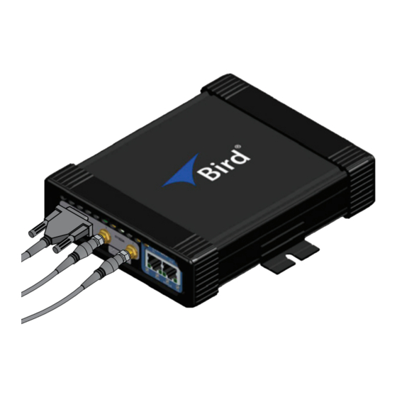
Introduction Connectors, Controls and Indicators Figure 7 BDS II Front Panel Item Name Description Sensor Data Sensor temperature / data connector (DB-9), male Serial Port Sensor RF Input Current sensor connector Current Sensor RF Input Voltage sensor connector Voltage EtherCAT - IN EtherCAT control network input port EtherCAT - OUT EtherCAT control network output port Link/Activity... - Page 20 Bird Diagnostic System Figure 8 BDS II Rear Panel Item Name Description RATE Device Net DeviceNet baud rate switch DeviceNet DeviceNet network connector used for control via a DeviceNet Interface network. Connector SYNC Input Sync input used for pulse and multi-level pulse operation.
-
Page 21: Theory Of Operation
Theory of Operation The Bird Diagnostic System (BDS) is a real-time RF measurement system that consists of a sensor, a sensor cable, and a receiver. Each component of the BDS (sensor, sensor cable, receiver) is calibrated separately and contains its own calibration constants which permits interchangeability without recalibration. -
Page 22: Chapter 2 Installation
If the shipping container is not damaged, unpack the unit. Save shipping materials for repackaging. 2. Inspect unit for visual signs of damage. Note: If there is damage, immediately notify the shipping carrier and Bird Technologies. Installing the Receiver CAUTION Do not block airflow to fan or air vents. -
Page 23: Installing The Sensor
Installation Figure 11 BDS Receiver Mounting Installing the Sensor CAUTION Bending RF cables can cause damage. When routing RF cables, the minimum bend radius is 0.5 inch (12.7 mm). Do not bend the cables more than the minimum bend radius. Failure to comply may result in permanent damage to the cable and reduced equipment performance. -
Page 24: Connecting The Sensor And Receiver Cables
Bird Diagnostic System Connecting the Sensor and Receiver Cables CAUTION Do not over tighten SMA connectors. Over tightening can deform the connectors and adversely impact system calibration. 1. Connect the current and voltage cables to the sensor ( Figure 12 on page 13 Torque the SMA connectors to 4.5 in-lb (0.5 Nm). -
Page 25: Installing The Bds Graphical User Interface Application
Installation Installing the BDS Graphical User Interface Application 1. Run 7001A992-X_BDS2GUI_setup-X.exe. Note: This will create a shortcut under the start menu folder “Start->All Programs->Bird->BDS2 GUI.” 2. Copy the shortcut onto the PC’s desktop (optional). Installing a BDS Receiver Option License Options are available to extend the functionality of the BDS Receiver. -
Page 26: Chapter 3 User Interface Description
Chapter 3 User Interface Description BDS Ethernet Interfaces There are two BDS Receiver user interfaces, the BDS Web UI and the BDS GUI. BDS Web UI — The Web UI is used to manage the BDS Receiver’s firmware, licenses, IP address, time settings, and login credentials. -
Page 27: Web Ui Login
User Interface Description Figure 15 Web UI Homepage Web UI Login To display the Login screen, click the Login button on the left side of the Web UI screen. Enter the Login and password to access the BDS Receiver’s configuration utilities. Default Login: admin Default Password: admin Figure 16... -
Page 28: Setup
Bird Diagnostic System Setup The setup menu provides the tools for changing the BDS receiver’s IP Address and the option of configuring a time server. Network Settings The BDS receiver is capable of operating with a static IP address or set to be dynamically assigned an IP address by a DHCP server. -
Page 29: Security
User Interface Description System Settings The System settings tab can be used to turn on and off internal case lighting or do a soft reboot of the BDS Receiver. Figure 20 on page 19 Figure 20 System Settings Menu Security The Security menu allows the user to change the password. - Page 30 Bird Diagnostic System Save — Applies the changes to the BDS. A system reboot is required. Transient Detection Menu Figure 23 Transient Detection Menu Enable Transient Detection — Enables/Disables Transient Detection. Default Value: Unchecked (Transient Detection disabled) Ref Frequency —...
-
Page 31: Updates
User Interface Description Updates The Updates menu is used for installing BDS Receiver Firmware updates, see Installing BDS Receiver Firmware Update on page 68 Figure 24 Firmware Update Menu License The License Menu is used for installing BDS Receiver options. See . -
Page 32: Graphical User Interface
Bird Diagnostic System Graphical User Interface The BDS 2 GUI is used to configure the BDS receiver and obtain measurement data from the system. There are three modes of operation: Standard Tracking, Spectral Search, and Time Domain. In addition, the BDS provides arc/transient detection capability that is available in Standard Tracking and Spectral Search modes. - Page 33 User Interface Description Figure 27 Save/Recall Setup Menu Options Exit — Closes the BDS GUI application. Note: Automatically stops data acquisition and disconnects from the BDS receiver. Connection Menu Open — Establishes a connection to the BDS receiver. Close — Closes the current connection to the BDS receiver.
- Page 34 Bird Diagnostic System View Menu Offers menu items for selecting a new view of a BDS document, configuring a view, or showing toolbars. The menu is context-sensitive to the currently active mode (Tracking or Spectral Search). Standard Tracking Mode View Menu Items —...
-
Page 35: File Options Dialog Box
User Interface Description Help Menu About — Displays the “About” dialog, showing the application version and date information. File Options Dialog Box This option is on the menu. The BDS GUI can be configured to automatically save data at the end of a File Menu data acquisition. -
Page 36: New Connection Dialog Box
Bird Diagnostic System New Connection Dialog Box The BDS GUI communicates with the receiver over Ethernet. In order to establish a connection to the BDS receiver you first need to make sure that the receiver and PC are on the same subnet, see... -
Page 37: Status Bars
User Interface Description Graph (View) Table — Displays the active BDS document data in tabular format. Time Plot — Displays the active BDS document data plotted on a graph over time. Note: That this will display a “Sweep View” if in Spectral Search mode. Smith Chart —... -
Page 38: Mode Configuration Dialog Boxes
Bird Diagnostic System BDS Document Each document window has its own status bar. The document status bar has six indicator fields (from left to right): Scan — Displays “SCAN” if the document is collecting data from the BDS. Displays “IDLE” when not collecting. - Page 39 User Interface Description Figure 31 Frequency Selection Dialog Single Frequency — Allows selection of a single frequency, when a frequency is entered using this option, any previously selected frequencies are removed from the Selected Frequencies list Fundamental Groups — Drop-down menu contains the fundamentals available for selection. Fundamental —...
- Page 40 Bird Diagnostic System Active Measurements — Displays all frequencies that have been added to the measurement configuration. Frequencies are listed in MHz. Column headers (from left to right): Fundamental in MHz Harmonic (overtone) number (1-5) Intermod number (-3 to 3, 0 means no IMD) ...
- Page 41 User Interface Description Multi-Level Pulse - Rising edge of sync pulse is used to start measurement period, up to four pulse states, for each fundamental, may be measured during the measurement period, receiver tracks frequency during each individual state. States are defined in the area below.
- Page 42 Bird Diagnostic System Averaging The BDS offers two types of data averaging for Standard Tracking Mode: Simple (Fixed) or Moving. Both averaging modes will reduce signal-to-noise ratio in a measurement. Averaging is performed in the receiver. Figure 33 Averaging Dialog A simple average will take a number of measurements and then compute and report the average value after the number of measurements has been sampled.
- Page 43 User Interface Description Free Run Figure 35 Free Run Dialog Use the Free Run scan mode to scan for data until the specified number of datasets have been collected or a timer expires, whichever happens first. No. Datasets — Specifies the number of datasets to collect. Avg Power time —...
- Page 44 Bird Diagnostic System Trigger Capture Limits Continuous Trigger (Restart After Previous Trigger End) — When selected the BDS will automatically reset the trigger state and wait for a new trigger event. If auto-save is used, this will create a new document after saving the old one. The same document window is used.
- Page 45 User Interface Description Example - A Trigger Delay of 40% would equal 8.19 ms worth of data post-trigger and 12.29 ms worth of data pre-trigger. Min ADC Level — Min ADC Level specifies the minimum count level to accept a transient event. This is used to prevent spurious transient events, especially events reported when measuring the noise floor.
-
Page 46: Spectral Search (Sweep) Mode Options
Bird Diagnostic System Spectral Search (Sweep) Mode Options Sweep The “Sweep” page provides options for defining the frequency band. Figure 38 Sweep Dialog Frequency Step Size — This option allows for the selection of either Linear step size, where each step is the same, or Logarithmic step size, where frequencies increase exponentially. - Page 47 User Interface Description Default Settings — Clicking this button will restore the default sweep settings. Frequency Step Size: Linear No. Points: 991 (Fixed) Start Frequency: 1 MHz Stop Frequency: 100 MHz Frequency Step: 47.165 kHz ...
- Page 48 Bird Diagnostic System Peak Locator This page controls the peak locator algorithm that runs on each set of sweep data. Figure 41 Peak Locator Dialog No. Peaks — Specify the number of peaks to locate and define the noise threshold in dB that defines a peak.
-
Page 49: Time Domain Mode Options
User Interface Description Time Domain Mode Options Time Domain Measurement Tab The Time Domain Measurement tab is used to define a frequency for the BDS to monitor while in Time Domain Mode. Figure 43 Time Domain Measurement Dialog Single Frequency — Allows the user to enter a frequency not available on the fundamental list. - Page 50 Bird Diagnostic System Time Domain Trigger Tab Figure 44 Time Domain Trigger Tab Trigger Mode — User can set for the time domain acquisition to begin on a rising or falling edge of the signal. Internal — User can select between using an internal trigger based on the upper and lower thresholds.
-
Page 51: Chapter 4 Operating Instructions
Applying Power The Bird Diagnostic System receiver has a power input connector on the rear panel, the supplied BDS power supply should be secured to the BDS using the screw-on barrel connector. The power switch on the rear panel is used to apply and remove power to the BDS circuitry. -
Page 52: Establishing A Connection To The Bds Receiver
Bird Diagnostic System Establishing a Connection to the BDS Receiver Direct Connection — A direct connection uses a single Ethernet cable connecting the BDS Receiver to a PC, as shown in Figure 45 When using a direct connection, the IP address on the PC must be set to an address that will allow the PC to connect to the BDS Receiver. -
Page 53: Restoring Pc Network Connection To Dhcp
Operating Instructions 6. Enter the following settings: IP address: 192.168.0.100 Subnet mask: 255.255.255.0 (Gateway is ignored) Note: These settings will allow the PC to communicate with a BDS Receiver with default IP configuration, if the BDS Receiver’s IP configuration has been changed, the PC’s IP configuration must be set for the same subnet as the BDS Receiver. -
Page 54: Select Mode Of Operation
Bird Diagnostic System 8. Click the Connect button. Note: “CONNECTED” should be displayed in the left-most indicator field of the main status bar at the bottom of the application window. Note: The BDS GUI will save your connection settings as defaults. If disconnected from the receiver, a connection can be reestablished by either clicking the “Connection”... -
Page 55: Using Standard Tracking Mode
Operating Instructions Using Standard Tracking Mode This section provides the minimum steps required to configure the BDS receiver in Standard Tracking Mode. There are many settings and options available in the Standard Mode of operation. For more information about Standard Tracking Mode options, refer to "Standard Tracking Mode Configuration"... -
Page 56: Acquiring Fresh Data
Bird Diagnostic System 7. Select Tracking Settings for each fundamental: CW - continuous measurement, no sync pulse required, receiver tracks the fundamental frequency during measurement. Pulse - Sync Pulse is used to determine measurement period, receiver only tracks and measures signal during active sync pulse. -
Page 57: Saving The Document
Operating Instructions Saving the Document Select File -> Save As… from the main menu. See Figure 48 on page 47 Note: If the data will be analyzed using another application such as MS Excel, see "Viewing Captured Data Using MS Excel" on page 60 Figure 48 Saving the Document in Standard Tracking Mode... -
Page 58: Viewing The Data
Bird Diagnostic System Viewing the Data Data can be viewed while it’s being collected or after a data acquisition completes. The data is displayed in the following formats: Table Time plot Smith chart These views can be accessed and switched at any time by: ... - Page 59 Operating Instructions Attn V (dB) -The attenuation applied (in dB) to the voltage channel during this frequency measurement. Attn I (dB) -The attenuation applied (in dB) to the current channel during this frequency measurement. Step - Indicates the step of the recipe. The data table displays the following information for each harmonic component returned in the dataset: ...
- Page 60 Bird Diagnostic System Time Plot View Figure 50 Data Viewed in Time Plot Format Note: The Time Plot view displays each dataset over time. The dataset number is displayed on the X- axis. Time Plot Display Options The Time Plot display options are available by selecting “View->Options…” from the menu bar or by right clicking anywhere on the display and selecting “Options…”...
- Page 61 Operating Instructions Smith Chart View Figure 52 Data Viewed in a Smith Chart Note: The Smith Chart view displays data normalized to 50 Ohms (a value of 1 on the horizontal axis represents 50 Ohms). Smith Chart Display Options The Smith Chart display options are available by selecting “View->Options…” from the menu bar or by right clicking anywhere on the display and selecting “Options…”...
-
Page 62: Using Spectral Search (Sweep) Mode
Bird Diagnostic System Using Spectral Search (Sweep) Mode To collect data in the Spectral Search Mode you can simply use the default sweep configuration and then start a Sweep. There are many settings and options available in the Spectral Search Mode of operation. - Page 63 Operating Instructions Viewing Data in the Frequency Domain Figure 54 Viewing Data in the Frequency Domain Note: Each data point is displayed as amplitude over frequency, with frequency on the x-axis. Amplitude display formats can switched by right-clicking on the graph and selecting one of the format types from the pop-up window: ...
- Page 64 Bird Diagnostic System Note: Displays “Yes” if automatic gain control is used or “No” if manual gain control is used. Cal – Measurement calibration indicator. Note: Displays “Yes” if the sweep data has been calibrated or “No” if it has not been calibrated.
-
Page 65: Using Time Domain Mode
Operating Instructions Using Time Domain Mode Time Domain mode is an option available for the BDS receiver. The Time Domain mode allows unprecedented visibility into the shape of pulsed RF waveforms in the non 50-Ohm environment. Very similar to an oscilloscope, the BDS will display a one-shot, triggered view of the pulse envelope. -
Page 66: Setting The Minimum Configuration
Bird Diagnostic System Setting the Minimum Configuration 1. On the mode menu, select Switch Mode -> Time Domain Mode (TD). 2. Then select Mode -> Options… or click the pulse icon on the “Options” toolbar to open the Time Domain Mode Configuration dialog box. - Page 67 Operating Instructions External Trigger - The time domain sweep will be synchronized with the externally applied SYNC signal. Internal Auto - The time domain sweep will trigger automatically when the user-defined trigger thresholds are satisfied. Set the trigger thresholds (used only for Internal Auto mode) For rising-edge trigger, the lower threshold condition must be met, followed by the upper threshold condition without violating the settling or expire time.
-
Page 68: Acquiring Fresh Data
Bird Diagnostic System Acquiring Fresh Data Select Mode -> Start Time Domain (TD) from the main menu to start the data acquisition. Note: Clicking the green Run button on the “Scan” toolbar will also start an acquisition. Stopping Data Acquisition The data acquisition can be stopped at any time by performing one of the following: ... - Page 69 Operating Instructions Viewing Data in the Time Domain Figure 58 Viewing Data in the Time Domain Note: Each data point is displayed as amplitude over time, with time on the x-axis. Right click on the graph to display the graph options and markers. Markers —...
-
Page 70: Viewing Captured Data Using Ms Excel
Bird Diagnostic System Viewing Captured Data Using MS Excel in Using Standard Tracking Mode or see "Saving the Document" on page 47 "Saving the Document " on page in Using Spectral Search (Sweep) Mode for details on saving data files. - Page 71 Operating Instructions Table 4 Spectral Search Mode CSV Format Description Column Header Description AttnV Attenuation applied to the voltage channel while measuring the point. AttnI Attenuation applied to the current channel while measuring the point. Frequency (Hz) Frequency reported for the step point in Hz. RMS Voltage (Volts) RMS Voltage reported for the step point.
- Page 72 Bird Diagnostic System Table 6 Transient Detect CSV Format Description Column Header Description Voltage ADC Voltage ADC counts. Range: 0-127 for 8-bit, 0-2047 for 12-bit mode. Current ADC Current ADC counts. Range: 0-127 for 8-bit, 0-2047 for 12-bit mode. Voltage Attn Attenuation applied to the voltage channel in dB.
-
Page 73: Chapter 5 Maintenance
Clean the connector contacts with alcohol or dry cleaning solvent. Cleaning To clean the Bird Diagnostic System receiver, use only a soft cloth dampened with mild detergent and rinse with water. Clean the sensor with alcohol or a dry cleaning solvent that leaves no residue. -
Page 74: Changing Bds Receiver's Ip Address
Bird Diagnostic System Changing BDS Receiver’s IP Address Figure 60 Network Settings Menu 1. Log into the WebUI, see "Web UI Login" on page 63 2. Click Setup menu. 3. Click Network Tab. 4. Select IP Address Mode: Static IP - If selected, the new IP Address, subnet mask, and Gateway must be entered manually ... -
Page 75: Update Bds Receiver's Time Setting
Maintenance Update BDS Receiver’s Time Setting Figure 61 Time Settings Menu 1. Log into the WebUI, see "Web UI Login" on page 63 2. Click Setup menu. 3. Click Time Tab. 4. Select Update Time check box. 5. Click << button or >> button to select the current month and year. 6. -
Page 76: Installing An Option License
Bird Diagnostic System Installing an Option License Options are available to extend the functionality of the BDS Receiver. An option license must be installed on the BDS receiver to activate a purchased option. The following steps are required to install a license. - Page 77 Maintenance Figure 64 Upload Option File to BDS Receiver 7. Once the file is successfully uploaded, click Activate License. See Figure 65 Figure 65 License Activation 8. Click Reboot to complete License activation, see Figure 66 Figure 66 Reboot BDS Receiver 9.
-
Page 78: Installing Bds Receiver Firmware Update
Bird Diagnostic System Installing BDS Receiver Firmware Update Obtain Firmware Firmware files for the BDS Receiver may be downloaded from the product page on Birdrf.com. 1. Download the Firmware File (.zip file). 2. Save the license file on the PC you will use to install the license on the BDS receiver. - Page 79 Maintenance Figure 69 Firmware Installation Reboot 9. Refer to the LEDS on the front panel of the BDS. Once the unit has finished rebooting the three status LEDs are glowing green. Note: wait 20 seconds after the three status LED’s are green before continuing. 10.
-
Page 80: Specifications
Bird Diagnostic System Specifications General Specifications Parameter Specification Max RF power is sensor dependent. See Figure 72 RF power, max for max power of a standard sensor. on page 71 Frequency range 307 kHz - 252 MHz (sensor dependent) Frequency resolution... - Page 81 Maintenance Figure 72 BDS System Max Power...
-
Page 82: Tracking Mode Specification
Bird Diagnostic System Tracking Mode Specification Parameter Specification Signal Type CW, pulse, and multi-level pulse Frequency Tracking Up to 2 GHz/s Pulse Characteristics PRR ≤ 10 kHz, Duty cycle 5% – 95% (5 us min. pulse width) Pulse Gate External TTL (0 to 24V tolerant) -
Page 83: Ethernet Specification
Maintenance Ethernet Specification Parameter Specification 10/100/1000BASE-T (auto-sensing) Interface Version 2.0/IEEE 802.3 Protocol TCP/IP Voltage, Current and Phase Measurement Characteristics Parameter Voltage Current Phase Angle –180° to +180° Measurement Range 1-3000 Vrms 0.1 – 100 Arms IEEE 754 Single Precision Floating Point Resolution Absolute Angle: Uncertainty... -
Page 84: Physical And Environmental
Sensor Data Input 9-pin D-sub, male Pulse Gate / Trigger Input 7001A900-2 SMB, female 7001A900-3 SMA, female EtherCAT (7001A900-2 only) RJ-45 (x2) (Factory Diagnostic only) RS-232 (7001A900-3 only) 9-pin D-sub, female DeviceNet Lumberg RSWF5-PCB 5-pin circular (Factory Diagnostic only) Ethernet... -
Page 85: Optional Accessories
Maintenance Optional Accessories QC Connectors Connector Description 4240-002 7/8 in. Swivel Flange EIA 4240-012 QC M-LT 4240-018 QC F-LT 4240-025 QC M-LC 4240-031 QC F-LC 4240-050 QC F-UHF 4240-062 QC F-N 4240-062-2 QC F-N, silver plated 4240-062-3 QC F-N, gold contact 4240-063 QC M-N 4240-063-2... - Page 86 Bird Diagnostic System Connector Description 4240-260 QC 1-5/8 in. flanged EIA adapter 4240-268 QC F-HN 4240-278 QC M-HN 4240-318 QC M-LC 4240-334 QC M-SMA 4240-336 QC F-SMA 4240-344 QC F-IEC 7/16 coaxial 4240-346 QC F-Mini UHF 4240-353 QC M-SC 4240-363...
-
Page 87: Mounting Hardware
Any maintenance or service procedure beyond the scope of those in this chapter should be referred to a qualified service center. If the unit needs to be returned for any reason, request an Return Material Authorization (RMA) through the Bird Technologies website. All instruments returned must be shipped prepaid and to the attention of the RMA number. -
Page 88: Chapter 6 Rs-232 Serial Control
Chapter 6 RS-232 Serial Control BDS receivers equipped with an RS-232 9-pin serial connector are capable of outputting measurement data over a serial data connection. The RS-232 interface conforms to the EIA/TIA-232E and ITU-T V. 28 specifications. Prior to using this feature, the BDS receiver must be set up via the Graphical User Interface to measure frequencies of interest, see "Operating Instructions"... -
Page 89: Rs-232 Serial Connection Settings
RS-232 Serial Control RS-232 Serial Connection Settings The device communicating with the BDS Receiver via RS-232 must be configured with the following settings. Speed: 115200 Data: 8 bit Parity: odd Stop Bits: 1 bit Flow Control: none Measurement Reporting Command/Response Strings Prior to communicating over RS-232 serial bus with the BDS receiver, RS-232 data reporting must be enabled in the GUI, see... -
Page 90: Response
Bird Diagnostic System Command Description SD3X send all configured inter-mod data for the 3rd fundamental. Response RS-232 Data Reporting is NOT Enabled in the GUI A not acknowledged (NAK) response is sent by the BDS receiver if the SD command is sent but RS-232 data reporting is NOT enabled in the GUI. -
Page 91: Transient Reporting
RS-232 Serial Control Transient Reporting A transient detection message (ARC) is sent by the BDS Receiver if a transient is detected and the transient detection reporting over RS-232 is selected in the GUI, see "Transient Detection Reporting Over RS-232" on page 78 The format of the transient detection message is shown below: ARC\n\r No additional information is reported with this message, to view the data associated with the transient detection... -
Page 92: Limited Warranty
Limited Warranty All products manufactured by Seller are warranted to be free from defects in material and workmanship for a period of one (1) year, unless otherwise specified, from date of shipment and to conform to applicable specifications, draw- ings, blueprints and/or samples. Seller’s sole obligation under these warranties shall be to issue credit, repair or replace any item or part thereof which is proved to be other than as warranted;...
Need help?
Do you have a question about the 7001A900-2 and is the answer not in the manual?
Questions and answers