Table of Contents
Advertisement
Quick Links
Advertisement
Table of Contents

Related Manuals for Chauvin Arnoux HandScope CA 922


Summary of Contents for Chauvin Arnoux HandScope CA 922
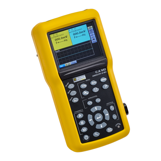
- Page 1 EN - User’s manual CA 922 - 20 MHz CA 942 - 40 MHz Portable Oscilloscopes...
- Page 2 Equipment protected by double insulation. Chauvin Arnoux has adopted an Eco-Design approach in designing this appliance. Analysis of the complete lifecycle has enabled us to control and optimize the effects of the product on the environment. In particular this appliance exceeds regulation requirements with respect to recycling and reuse.
-
Page 3: Table Of Contents
CONTENTS 1. FIRST START-UP .................................6 1.1. Unpacking ..................................6 1.2. Accessories .................................6 2. DESCRIPTION OF THE INSTRUMENT ..........................7 2.1. Presentation ................................7 2.2. Power supply ................................7 2.3. Batteries ..................................7 2.4. Channel insulation ...............................8 2.5. CA 922 & CA 942 .................................9 2.6. Advice for use of the sensors ............................10 2.7. - Page 4 16. MULTIMETER MODE "THE MEASUREMENT MENU" ....................51 16.1. THE "MEASUREMENT" menu ..........................51 16.2. Description ................................51 17. MULTIMETER MODE "THE CHANNEL A OR B MENU" .....................54 17.1. The channel "A" or "B" menu ...........................54 17.2. Notes ..................................54 17.3. Example : Multimeter coupling ..........................55 18.
- Page 5 36. COMMANDS SPECIFIC TO THE INSTRUMENT "OSCILLOSCOPE MODE" ............80 36.1. Vertical ..................................80 36.2. Trigger ..................................81 36.3. Horizontal ................................83 36.4. Display ..................................84 36.5. Measure ...................................84 36.6. Memory ..................................87 36.7. Utilities ..................................89 36.8. Help ..................................92 37. COMMANDS SPECIFIC TO THE INSTRUMENT "MULTIMETER MODE" ..............93 37.1.
-
Page 6: First Start-Up
1. FIRST START-UP 1.1. UNPACKING ⑨ ① ⑥ ⑤ ⑧ ③ ⑩ ④ ⑦ ATTESTATION DE VERIFICATION CHECKING ATTESTATION 190, rue Championnet Numéro de l'appareil : 75876 PARIS Cedex 18 FRANCE Equipment number ... -
Page 7: Description Of The Instrument
2. DESCRIPTION OF THE INSTRUMENT 2.1. PRESENTATION The particularity of these oscilloscopes is that they group 3 instruments in one: „ a laboratory digital oscilloscope for the analysis of electronic and electrotechnical signals, „ a 2-channel, 8000-count multimeter, „ a harmonic analyser, for the simultaneous decomposition of 2 signals with their fundamental and their first 31 harmonics. The instrument operates at a constant acquisition depth of 2,500 points. -
Page 8: Channel Insulation
2.3.1. CHARGE The batteries are charged when the oscilloscope is powered off but connected to the external power supply. During the fast charge of the batteries, the front-panel LED is on. It flashes in the following situations: „ pre-charge of very flat batteries „... -
Page 9: Ca 922 & Ca 942
The use of accessories with a voltage and/or category lower than 600 V CAT III reduces the operating range to the lower voltages and/or categories. Your oscilloscope is rated 600 V CAT III; at least 600 V CAT III accessories must be used. The accessories shipped with the instrument allow this. -
Page 10: Advice For Use Of The Sensors
2.5.3. MEASUREMENT TERMINAL External power supply connector Input Channel "B" Input Channel "A" 2.5.4. SIDE Isolated optical connector 2.6. ADVICE FOR USE OF THE SENSORS 2.6.1. CONNECTION OF THE REFERENCE CONDUCTORS TO THE SENSOR Distribution of stray capacitors: It is imperative, considering the stray capacitances, to correctly connect the reference conductors for each sensor. The conductors should preferably be connected to the cold points to avoid the transmission of noise by the stray capacitance between modes. -
Page 11: Sensor Calibration
The noise of the digital ground (earth) is sent to the analogue input by the stray capacitance. Reminder: In order to prevent electric shocks or possible fires: Never use accessories on which the casing is accessible if it has a voltage of > 30 Vrms compared to the earth. This precaution is necessary for example for sensors with an accessible metal BNC. - Page 12 Select the DC coupling for the channel to which the sensor is connected and run an autoset (icon opposite) to carry out pre-setting. Adjust the sensitivity and the vertical offset of the channel so that the signal fills the screen, and adjust the time base to 200 µs to view a signal period on the screen.
-
Page 13: Front Panel Description
2.8. FRONT PANEL DESCRIPTION The main functions of the instrument are accessed from the front panel. 2.8.1. ON / OFF KEY The instrument is switched on by a short press on the key shown opposite. It is switched off by a long press (a shutdown message appears and a beep sounds). -
Page 14: Oscilloscope Mode "The Keys
3. OSCILLOSCOPE MODE "THE KEYS" Pressing this key selects the "Oscilloscope" mode. 3.1. "MENU" KEY Trigger Trig displays the main "Trigger" menu Acquisition displays the main "Acquisition" menu Tools displays the main "Tools" menu Measurement Meas displays the main "Measurement/Cursor" menu Memory displays the main "Memory"... -
Page 15: "Time Base" Keys
3.3. 2 "TIME BASE" KEYS increases the time base for acquisition up to 200 s. decreases the time base for acquisition down to 25 ns. 3.4. 2 "SENSITIVITY" KEYS increases the vertical sensitivity of the last channel selected, up to 5 mV. decreases the vertical sensitivity of the last channel selected, down to 200 V. -
Page 16: Oscilloscope Mode "Display
4. OSCILLOSCOPE MODE "DISPLAY" 4.1. DISPLAY Battery information zone, if level is low (*) 1. Channel data area 5. Secondary menu area 2. Area for main display 3. Time data area 4. Main menu area 4.2. CHANNEL DATA 4.2.1. "MAIN CHANNEL" AREA Channel AC, DC, GND Unit... - Page 17 4.2.2. "AUTOMATIC MEASUREMENT" AREA Automatic measurement Automatic measurement Automatic measurement Automatic measurement of channel A of channel B of channel A of channel B The selected automatic measurements are shown in this window. 1 or 2 measurements per channel can be selected. 4.2.3.
-
Page 18: Main Display
4.3. MAIN DISPLAY Horizontal trigger Vertical trigger level Reticle / crosshair position indicator Displayed Indication of the channels and its vertical level Automatic cursors attached to measurement 1 Cursor 1 Position Cursor 2 Position Selection of the indicator for manual indicator for manual zoom zone measurement cursors... -
Page 19: Oscilloscope Mode "The Menus
5. OSCILLOSCOPE MODE "THE MENUS" 5.1. DISPLAY Battery information zone, if level is low Secondary menu area Main menu area 5.2. ORGANIZATION The menus have two elements: „ a horizontal menu, called "main", located at the bottom of the screen; „... -
Page 20: Navigation
5.5. NAVIGATION 5.5.1. CLASSICAL NAVIGATION These keys are use to navigate in the main menu. These keys are used to: - navigate in the secondary menu, - set a vertical parameter (see § Vertical settings) 5.5.2. VERTICAL SETTINGS Vertical settings are recognized by the double arrows on the main menu tab. - Page 21 To quit the setting: - using the keys, select the quit tab from the secondary menu. - the arrows can then be used to navigate the main menu. 5.5.4. ACTIVATING A DIALOGUE WINDOW The settings that can be adjusted using a dialogue window can be recognized from the symbol on the menu tab.
-
Page 22: Oscilloscope Mode - The Channel "A" Or "B" Menu
6. OSCILLOSCOPE MODE - THE CHANNEL "A" OR "B" MENU 6.1. THE CHANNEL "A" OR "B" MENU Press one of these two keys. Menu Main menu „ sets and displays the numeric value of the vertical offset (*) „ selects the channel coupling (AC, DC, GND) See example 1. - Page 23 Examples : 6.1.1. CHANNEL COUPLING Injection of a 1 kHz, 2Vpp amplitude sinusoidal signal with an offset of 0.5 V: „ with AC coupling (the DC component is removed): „ with DC coupling (the entire signal is measured): „ in GND coupling:...
- Page 24 6.1.2. CHANNEL FILTER Superimposition of 2 sinusoidal signals with a frequency of 100 Hz and 3 MHz, respectively: „ without filter (both signals are sent): „ with the filter 5 kHz low-pass filter (the 3 MHz sinusoidal is cut): „ with the 1,5 MHz low-pass filter (the sinusoidal is partially cut):...
- Page 25 6.1.3. SENSOR FACTOR Observation of a sinusoidal signal of 2 Vpp and 100 Hz with a x 10 sensor: „ with the factor x 1: the amplitudes and sensitivity are incorrect (factor 10) „ with the factor x 10: the amplitudes and sensitivities are correct...
-
Page 26: Oscilloscope Mode "The Math Channel Menu
7. OSCILLOSCOPE MODE "THE MATH CHANNEL MENU" 7.1. THE "M CHANNEL" MENU Press this key. „ adjustment of the vertical offset for the Math channel or the stored trace „ selects a mathematical function „ selects the factor for the "Math" function 7.1.1. - Page 27 Example 1: M = A + B, addition of a 5 Vpp sine with a 5 Vpp square almost in phase: In our example the amplitude of the resulting signal is 10 Vpp. As the sensitivity of channel M is 1 Vpp, it can be seen that the trace overshoots but is contained on the screen by dividing the representation by 2: The sensitivity of the M channel becomes 2 V and the amplitude remains at 10 Vpp.
- Page 28 Example 2: M = A x B, multiplication of a 5 Vpp sine and square almost in phase: In our example, the peak amplitude of our mathematical function is 2.5 V * 2.5 V = 6.25 VV. As the channel M sensitivity is 1 VV (with the factor x 1), it can be seen that the trace overshoots and can be corrected by using the /2 coefficient.
- Page 29 Example 3: M = A ÷ B, division of a 5 Vpp sine and square almost in phase: As the positive voltages of signals A and B are equal, the division leads to a positive peak voltage of 1 V/V, and therefore a representation of 1 division on the trace.
-
Page 30: Oscilloscope Mode "The Trigger Menu
8. OSCILLOSCOPE MODE "THE TRIGGER MENU" 8.1. THE "TRIGGER" MENU Trig Press this key. „ selects the Trigger source and the trigger mode „ adjusts and displays the vertical trigger level „ sets and displays the event time position in relation to the trace area used to switch to the other menus... -
Page 31: Description
8.2. DESCRIPTION 8.2.1. TRIGGER SOURCE AND TRIGGER MODE Trigger Source Triggering mode Channel A automatic Channel A single shot Channel A triggered Channel B automatic Channel B signle shot Channel B triggered „ « Single shot » mode: Hold A single acquisition triggered by pressing the key opposite is authorised. -
Page 32: Examples
8.3. EXAMPLES 8.3.1. TRIGGER FILTER Display of a 1 kHz sine with noise (Acquisition Envelope ON) „ without trigger filter (we trigger on the edge of the 1 kHz signal but, depending on the noise value, we trigger on the rising or falling edge): „... - Page 33 „ with the Noise filter (the trigger hysteresis changes to 3 div., we trigger on the 1 kHz sine): 8.3.2. OTHER LF REJECT FILTER EXAMPLE Observation of a slow 10 Hz sine on which peaks show every 200 ms (PkDet activated) „...
- Page 34 This can also be achieved without a filter, but by slecting triggering on a pulse width of less than 1 µs :...
-
Page 35: Oscilloscope Mode "The Acquisition Menu
9. OSCILLOSCOPE MODE "THE ACQUISITION MENU" 9.1. THE "ACQUISITION" MENU Press this key. „ activates or deactivates the "Peak detection" menu See example 1 „ selects or deactivates averaging function factor See example 2 „ activates or deactivates the "Envelope" mode See example 3 „... -
Page 36: Examples
9.2. EXAMPLES 9.2.1. PkDet acquisition Observation of rapid pulse combs with a low repetition frequency. „ without PkDet (the repetition frequency of the combs gives an inappropriate sampling frequency for viewing the signal, so there are missing combs): „ with PkDet (the detection of the min and max obtained between two sampling steps makes it possible to view all the combs) : Peak detection deactivates ETS (Equivalent Time Sampling) reconstruction of a repetitive trace. - Page 37 9.2.2. ACQUISITION AVERAGING Observation of a 1 kHz sine with noise. Prior to averaging make sure that the trace is stable. In our example the Noise filter from the Trigger menu is activated. „ without averaging: „ with x 4 averaging (the noise is reduced) : „...
- Page 38 9.2.3. ENVELOPE ACQUISITION Observation of a sinusoidal signal with amplitude modulation. „ without envelope (an acquisition is viewed at each triggering): „ with envelope (an acquisition is displayed at each triggering):...
-
Page 39: Oscilloscope Mode "The Measurement Menu
10. OSCILLOSCOPE MODE "THE MEASUREMENT MENU" 10.1. THE "MEASUREMENT" MENU Meas Press this key. „ activates or deactivates automatic measurement display „ used to open the configuration windoaw for automatic measurements on the channel in question (by pressing the key opposite) (*) „... - Page 40 10.1.1. DESCRIPTION OF THE CONFIGURATION WINDOW FOR AUTOMATIC MEASUREMENTS Movement of the selection in the window Validation of the selection NAME MEASUREMENT DESCRIPTION AUTOMATIC CURSOR INDICATION Vmin minimum peak voltage Vavg and Vmin Vmax maximum peak voltage Vavg and Vmax peak-to-peak voltage Vmin and Vmax Vlow...
- Page 41 10.1.2. MEASUREMENT CONDITIONS „ The measurements are made on the entire depth of the acquisition. „ Any modification of the signal causes an update of the measurements. These are refreshed at the same rhythm as the acquisition. „ The accuracy of the measurements is optimal if two complete periods of the signal are displayed. 10.1.3.
-
Page 42: Oscilloscope Mode "The Memory Menu
11. OSCILLOSCOPE MODE "THE MEMORY MENU" 11.1. THE "MEMORY" MENU Press this key. „ activates or deactivates the reference display See example „ manages stored traces (.trc) „ manages stored traces (.txt) The .txt traces cannot be reloated on the HandScope but can be used in Spreadsheet software. -
Page 43: Example
11.1.2. STORAGE CAPACITY The memory's capacity is 2 MB (500 kb of which used by File System) and it can be used to store traces, screenshots, configurations and measurement files. The file names are generated automatically by incrementingthe file index from 00 to 99 (e.g.: trace-00.TXT, trace-01.TRC, setup-03. CFG, screen-10.BMP, meter-20.TXT …). -
Page 44: Description
11.3. DESCRIPTION 11.3.1. RECORDING MANAGEMENT „ Of a .trc trace „ Of a .txt trace „ Of a .cfg configuration „ Of a .bmp screenshot Example : Text zone indicating the name under which the file will be saved to the user. Trace selection Confirm or zone. -
Page 45: Oscilloscope Mode "The Tools Menu
12. OSCILLOSCOPE MODE "THE TOOLS MENU" 12.1. THE "TOOLS" MENU Press this key. This menu is the same in "Multimeter" and "Harmonic anlyser" modes. „ selects the language of warning or help messages: „ opens the "Rs / USB Information" window: „... -
Page 46: Oscilloscope Mode "The Help Key
13. OSCILLOSCOPE MODE "THE HELP KEY" 13.1. THE "HELP" KEY Press this key to activate / deactivate the integrated help function. In all modes it displays a help window for the current menu. Example : Main title of the current help A pointer placed opposite the lab of the secondary menu for... -
Page 47: Multimeter Mode "The Keys
14. MULTIMETER MODE "THE KEYS" Pressing this key selects the "Multimeter" mode; 2 independent 8,000-count digital multimeters are available. 14.1. 6 "MENU" KEYS Trigger Trig inactive in "Multimeter" mode. Acquisition inactive in "Multimeter" mode. Tools displays the main "Tools" menu, identical to the Oscilloscope mode Measurement Meas inactive in "Multimeter"... -
Page 48: Time Base" Keys
14.3. "TIME BASE" KEYS increases the recording time in the viewing window. decreases the recording time in the viewing window. 14.4. 2 "SENSITIVITY" KEYS increases the range of the last selected channel. decreases the range of the last selected channel. 14.5. -
Page 49: Multimeter Mode "Display
15. MULTIMETER MODE "DISPLAY" 15.1. DISPLAY Battery info.area (*) 1. Measurement zone 4. Secondary menu area 2. Graphic window area 3. Main menu area (*) If the measurement is not possible, dotted lines will be displayed. If the channel is not validated the measurement will be replaced by"-x-". -
Page 50: Graphic Window Area
15.3. GRAPHIC WINDOW AREA Depth of the display window Bargraph of channel B Bargraph of channel A Trend lines of channels A and B This window shows the measurement changes as a function of time, i.e.: „ the trend curves for the main measurement on each channel „... -
Page 51: Multimeter Mode "The Measurement Menu
16. MULTIMETER MODE "THE MEASUREMENT MENU" 16.1. THE "MEASUREMENT" MENU Meas Press this key „ selects the main measurement on channel "A" „ selects the secondary measurement displayed on the channels Channel "B" is assigned to voltage measurement, when possible. 16.2. - Page 52 16.2.2. POWER MEASUREMENT AND DIALOGUE WINDOW FOR "MEASUREMENT SELECTION" When selecting active power measurement, pressing on displays the window below. You can thus choose the measurement type: „ Single-phase „ Balanced three-phase without N „ Balanced three-phase with N 16.2.3. DISPLAY OF THE POWER MEASUREMENT AND FORCED TABS The power measurement imposes the following settings: - Channel A unit: V (volt)
- Page 53 16.2.4. SECONDARY MEASUREMENT Selects the secondary measurement displayed on the channels: activates the secondary monitoring measurement. This comprises three measurements: „ min the minimum measured value „ max the maximum measured value „ avg the average value since the last reset activates the relative secondary measurement.
-
Page 54: Multimeter Mode "The Channel A Or B Menu
17. MULTIMETER MODE "THE CHANNEL A OR B MENU" 17.1. THE CHANNEL "A" OR "B" MENU Press one of theses two keys Main menu Secondary menus „ selects the channel coupling (AC, DC, or AC+DC) See example „ activates or deactivates autorange „... -
Page 55: Example : Multimeter Coupling
17.3. EXAMPLE : MULTIMETER COUPLING In voltmeter mode, 3 types of coupling are possible: „ AC is used to measure the VAC RMS voltage of the signal without its DC component, „ DC is used to measure the signal's VDC voltage, „... -
Page 56: Multimeter Mode "The Memory Menu
18. MULTIMETER MODE "THE MEMORY MENU" 18.1. THE "MEMORY" MENU Press this key „ selects saved trace management (.txt) „ selects save configuration management (.cfg) „ selects saved screenshot management (.bmp) „ The .bmp file can be recovered on a PC using SX-METRO software/ Oscilloscope mode, import memory. „... -
Page 57: Harmonic Analyser Mode "The Keys
19. HARMONIC ANALYSER MODE "THE KEYS" Press this key selects the "Harmonic Analyser" mode. 19.1. "MENU" KEYS Trigger Trig inactive in "Harmonic Analyser" mode. Acquisition displays the main "Acquisition and Display" menu: access to orders of harmonics, averaging, zoom. Tools displays the main "Tools"... -
Page 58: "Time Base" Keys
19.3. 2 "TIME BASE" KEYS inactive in "Harmonic Analyser" mode. inactive in "Harmonic Analyser" mode. 19.4. 2 "SENSITIVITY" KEYS same as "Oscilloscope " mode. same as "Oscilloscope " mode. 19.5. 2 FUNCTIONAL KEYS same as "Oscilloscope" mode. Hold inactive in "Harmonic Analyser" mode. -
Page 59: Harmonic Analyser Mode "Display
20. HARMONIC ANALYSER MODE "DISPLAY" 20.1. DISPLAY The indication using a double black line on the harmonics corresponds to the representation of overshooting harmonics. Battery info. area (*) 1. Measurement area 5. Secondary menu area 2. Graphic window area 3. Harmonic reference area 4. -
Page 60: Harmonic Display Area
20.3. HARMONIC DISPLAY AREA Overshooting harmonics Channel B harmonic, same colour as the channel Channel A harmonic, same colour as the channel Vertical scale in percentage of the fundamental Horizontal scale harmonic number This area displays harmonics 1 to 16 of the validated channels in the form of a bar chart. The user can switch from the display of harmonics 2 to 16 to the display of harmonics 17 to 31. -
Page 61: Harmonic Analyser Mode "The Channel A Or B Menu
21. HARMONIC ANALYSER MODE "THE CHANNEL A OR B MENU" 21.1. THE CHANNEL "A" OR "B" MENU This menu operates in exactly the same way as in the "Oscilloscope" mode. Press one of these two keys. Main menu Secondary menus „... -
Page 62: Harmonic Analyser Mode "Acquisition Menu
22. HARMONIC ANALYSER MODE "ACQUISITION MENU" 22.1. THE " ACQUISITION" MENU Press this key. „ adjusts and displays the number of the selected harmonic Exit tab „ Avering Identical to "Oscilloscope" mode „ selects the vertical zoom factor 100 % of the fundamental 50 % of the fundamental 25 % of the fundamental 10 % of the fundamental... -
Page 63: Harmonic Analyser Mode "Memory Menu
23. HARMONIC ANALYSER MODE "MEMORY MENU" 23.1. THE "MEMORY" MENU This menu operates in exactly the same way as in the "Oscilloscope" mode. Press this key. „ manages stored configurations (.cfg) „ manages stored screenshots (.bmp) „ The .bmp file can be recovered on a PC using SX-METRO software/ Oscilloscope mode, import memory. -
Page 64: Remote Programming
24. REMOTE PROGRAMMING 24.1. PRESENTATION The oscilloscope can be programmed remotely from a computer: „ either using the SX-METRO software, „ or using basic standardised commands that comply with the IEEE488.2 standard and the SCPI protocol. This remote programming is used to: „... -
Page 65: Technical Specifications "Oscilloscope Mode
25. TECHNICAL SPECIFICATIONS "OSCILLOSCOPE MODE" Only the assigned tolerance or limit values are guaranteed (after 30 minutes to adapt to temperature). Values without tolerances are given for information purposes only. 25.1. VERTICAL DEFLECTION Specifications CA 922 CA 942 Number of channels 2 channels 5 mV to 200 V/div. -
Page 66: Horizontal Deflection (Time Base)
25.2. HORIZONTAL DEFLECTION (TIME BASE) Specifications CA 922 CA 942 from 25 ns to 200 s/div. such that : „ Actual time: from 200 s/div. to 5 µs/div. „ ETS: from 2.5 µs/div. to 125 ns/div. Time base calibres Zoomed ETS: 50 ns/div. and 25 ns/div. For time bases from 200 s/div. -
Page 67: Acquisition Chain
25.4. ACQUISITION CHAIN Specifications CA 922 CA 942 Resolution of the ADC 9 bits Maximum sampling frequency 50 MS/s in real time / 1 converter per channel Minimum width for detectable glitches: > 20 ns Transient capture MIN/MAX mode 1250 MIN/MAX couples Depth of acquisition memory 2500 pts per channel 25.5. -
Page 68: Measurement Processing
25.6. MEASUREMENT PROCESSING 25.6.1. MATHEMATICAL FUNCTIONS Choice from: „ opposite „ addition „ subtraction „ multiplication „ division The display is adjusted using a factor: / 5, / 2, x 1, x 2, x 5. 25.6.2. AUTOMATIC MEASUREMENTS Time measurements „... -
Page 69: Display
25.7. DISPLAY Specifications CA 922 CA 942 LCD 3.5’’ TFT (color display) Display screen Backlit LED Resolution 1/4 VGA, i.e. 320 horizontal pixels x 240 vertical pixels Complete memory: 2500 Window viewed in normal mode 540 pts from the 2500 in the complete memory Display modes Entire acquisition Display of all the samples acquired in a burst with linear interpolation between 2... -
Page 70: Technical Specifications "Accessories
26. TECHNICAL SPECIFICATIONS "ACCESSORIES" 1/10 Sensor Measurement category 600 V CAT III Bandwidth DC to 500 MHz Input capacitance 12 pF Compensation range 12 pF to 25 pF Rise time 0.9 ns Input impedance 10 MΩ DERATING see opposite Accessories wire holder and earth crocodile clip Measurement category 600 V CAT III... -
Page 71: Technical Specifications "Multimeter Mode
27. TECHNICAL SPECIFICATIONS "MULTIMETER MODE" Only the assigned tolerance or limit values are guaranteed (after 30 minutes to adapt to temperature). Values without tolerances are given for information purposes only. Display 8000 points for voltmeter Entry impedance 1 MΩ Max input voltage 600 Vrms sine and 600 VDC, without sensor Max floating voltgae 600 Vrms up to 400 Hz CAT III... - Page 72 Capacitance measurement On channel 1 Ranges Capacitance meter Resolution Measurement current 5 mF 1 µF 500 µA 500 µF 0.1 µF 500 µA 50 µF 0.01 µF 500 µA 5 µF 1 nF 500 µA 500 nF 100 pF 50 µA 50 nF 10 pF 2 µA...
-
Page 73: Network "Harmonic Analysis Mode
28. NETWORK "HARMONIC ANALYSIS MODE " Display of harmonics All of harmonics from 2 to 16 + Fundamental from 17 to 31 + Fundamental Fundamental frequency of the signal analysed from 40 to 50 Hz Measurement accuracy Fundamental level ± (2.5 % + 15 D) Level of harmonics ±... -
Page 74: General Specifications
30. GENERAL SPECIFICATIONS 30.1. ENVIRONMENT „ Reference temperature 18 °C to 28 °C „ Operating temperature 0 °C to 40 °C „ Storage temperature -20 °C to +60 °C „ Indoor use „ Altitude < 2000 m „ Relative humidity <... -
Page 75: Mechanical Specifications
31. MECHANICAL SPECIFICATIONS 31.1. BOX „ Dimension 214 x 110 x 57 mm „ Oscilloscope weight 0.960 kg with battery „ Power supply weight 0.160 kg 31.2. PACKAGING „ Dimensions 25 x 16.5 x 14.5 cm 32. SUPPLY 32.1. ACCESSORIES 32.1.1. -
Page 76: Maintenance
33. MAINTENANCE 33.1. CLEANING „ Disconnect the measurement probes or leads. „ Power down the instrument. „ Use a soft cloth moistened with soapy water. „ Rinse with a damp cloth. „ Dry rapidly with a dry cloth or forced air. „... -
Page 77: Remote Programming Manual
35. REMOTE PROGRAMMING MANUAL 35.1. PRESENTATION The oscilloscope can be remotely programmed with a computer, from simple standardized commands and using the optical inter- face USB-RS. The programming instructions comply with standard IEEE488.2, and the SCPI protocol (Standard Commands for Programmable Instruments). -
Page 78: Command Syntax
35.4. COMMAND SYNTAX 35.4.1. COMMON COMMANDS 35.4.2. SPECIFIC COMMANDS 35.4.3. KEY WORDS The brackets ([ ]) are used to frame a keyword which is optional during programming; i.e. the instrument will execute the command whether the keyword is optional or not. Uppercase and lowercase are used to differentiate the short form of the keyword (uppercase letters) and the long form (whole word). -
Page 79: Response Syntax
Reminder: The interpreter does not make any difference between capital and small letters. Example : to enter a duration of 1 micro second, it can be written either: 1us, or 0.000001, or 1e-6s, or 1E-3ms … This parameter can also be replaced by the following key words : „... -
Page 80: Commands Specific To The Instrument "Oscilloscope Mode
36. COMMANDS SPECIFIC TO THE INSTRUMENT "OSCILLOSCOPE MODE" 36.1. VERTICAL 36.1.1. DISPLAY DISPlay[:WINDow] :TRACe:STATe{[1]|2|3} (Command/Query) The DISP:TRAC:STAT{[1]|2|3} <1|0|ON|OFF> command validates or devalidates the selected signal. To the question DISP:TRAC:STAT{[1]|2|3}?, the instrument returns the validation status of the selected signal. Channel 3 corresponds to the MATH function. 36.1.2. -
Page 81: Trigger
36.1.3. FUNCTION DEFINITION CALCulate:MATH [:EXPRession] [:DEFine] (Command/Query) The CALC:MATH <(function)> command defines and activates the mathematical function. <function> is the definition of the mathematical function. Possible functions are: (-A), (-B), (A+B), (A-B), (A*B) ou (A/B). <(multiplier)> is the multiplier to be applied to the function. Possible multipliers are (1), (*2), (*5), (/2) ou (/5). - Page 82 TRIGger[:SEQuence {[1]|2}] :FILTer:LPASs[:STATe] (Command/Query) To the question TRIG:FILT:LPAS?, the instrument returns the activation status the reject of the high frequencies associated to the trigger source. 1|ON: activates the high frequencies reject (HF Reject coupling) „ 0|OFF: deactivates the high frequencies reject; the DC coupling is then activated. „...
-
Page 83: Horizontal
36.2.2. TRIGGER MODE - AUTOMATIC MODE TRIGger[:SEQuence {[1]|2}] :ATRIGger[:STATe] (Command/Query) The TRIG:ATRIG <1|0|ON|OFF> command validates or devalidates the automatic trigger. ON|1 activates the auto trigger mode „ OFF|0 activates the trigger mode „ To the question TRIG:ATRIG ?, the instrument returns the activation of the auto trigger. 36.2.3. -
Page 84: Display
36.4. DISPLAY 36.4.1. DISPLAY MODE DISPlay[:WINDow]:TRACe :MODE (Command/Query) The DISP:TRAC:MODE <ENVelope|ALL> command selects the sample display mode. ENVelope : displays in the "Envelope" mode „ ALL : displays in the "All acquisition" mode „ To the question DISP:TRAC:MODE?, the instrument returns the active display mode. 36.4.2. - Page 85 MEASure:AMPLitude? (Query) To the question MEAS: AMPLitude? <INT{1|2|3}> the instrument returns the amplitude of the selected signal. Response format: <measured value><NL> value in format <NR3> expressed in volt. MEASure:AC? (Query) To the question MEAS:AC? <INT{1|2|3}> the instrument returns the RMS voltage of the selected signal. Response format: <measured value><NL>...
- Page 86 MEASure:PERiod? (Query) To the question MEAS:PERiod? <INT{1|2|3}> the instrument returns the period of the selected signal. Response format: <measured value><NL> value in format <NR3> expressed in second. MEASure:FREQuency? (Query) To the question MEAS:FREQ? <INT{1|2|3}> the instrument returns the frequency of the selected signal. Response format: <measured value><NL>...
-
Page 87: Memory
DISPlay[:WINDow]:CURSor :TIME{[1]|2}:POSition (Command/Query) The DISP:CURS:TIME{[1]|2}:POS <position|MAX|MIN> command sets the horizontal position of the selected manual cursor. This command acts on the manual cursors represented on the screen by the X-Symboles (cursor 1) and * (cursor 2). The indexes {[1]|2} associated to the TIME key word select the same cursors. <position>... - Page 88 TRACe:LIMit (Command/Query) The TRAC:LIM <abscissa1>,<abscissa2>,<step> command sets the left and right limits and the step of the data to be transferred. <abscissa1>,<abscissa2>,<step> are parameters using format NR1. Their default value is 0, 2499 and 1. To the question TRAC:LIM?, the device returns the left and right limits and the step of the data to be transferred.
-
Page 89: Utilities
FORMat[:DATA] (Command/Query) The FORM <INTeger|ASCii|HEXadecimal|BINary> command selects the data format of the trace transfer. INTeger: The data transmitted consists in whole numbers, unsigned with a length of 32 bits, „ preceded by the heading #an. n represents the number of data items to transmit. a gives the number of figures making up n. - Page 90 MMEMory:DATA (Command/Query) The MMEM:DATA <"file">,<block> command transfers a file from the PC to the device. <"file"> consists in a name of 20 letters maximum, followed by a period and the 3-letter extension. If the file already exists, it will be overwritten by the new file. The text files (".txt") cannot be imported from the PC to the device.
- Page 91 36.7.3. RUN/STOP INITiate:CONTinuous :NAME (Command) The INIT:CONT:NAME <{EDGE|PULse}>,<1|0|ON|OFF> command starts or stops the acquisition in repetitive mode in the indicated trigger mode. ABORt (Command) The ABOR command aborts the acquisition in progress. If the instrument is set in the single mode, the acquisition is stopped. The instrument stays in the „...
-
Page 92: Help
36.8. HELP HELP[?] (Query) To the question HELP? [« directory entry »] the instrument answers helping in the SCPI commands available. « directory entry » is a key word (short or long form) of first level in the tree of the command. No distinction is made between small and capital letters. -
Page 93: Commands Specific To The Instrument "Multimeter Mode
37. COMMANDS SPECIFIC TO THE INSTRUMENT "MULTIMETER MODE" 37.1. VERTICAL INPut{[1]|2|3|4}:DMM :COUPling (Command/Query) The INP{[1]|2}:DMM:COUP <AC|DC|ACDC> command affects the coupling of the selected channel. To the question INP{[1]|2}:DMM:COUP? the instrument returns the current coupling of the selected channel. INPUT{[1]|2|3|4}:DMM :BANDwidth:AUTO (Command/Query) The INP{[1]|2}:DMM:BAND:AUTO <1|0|ON|OFF>... -
Page 94: Recording Time
37.2. RECORDING TIME [SENSe]:SWEep:TIME[?] (Command/Query) The SWE:TIME <time|MAX|MIN|UP|DOWN> command sets the recording time. <time> is a value in NRf format and may be followed or not by a multiple of the unit. By default, it is expressed in second. To the question SWE:TIME? the instrument returns the recording time. Response format: <time><NL>... - Page 95 37.4.2. EXECUTION ERRORS: (-299 TO -200) They indicate that an error has been detected at the moment of command execution and causes event register bit 4, called EXE, Execution Error, to be set to 1. -200 Execution error -213 Init ignored -221 Settings conflict -222...
-
Page 96: Ieee 488.2 Common Commands
38. IEEE 488.2 COMMON COMMANDS 38.1. INTRODUCTION The common commands are defined by the IEEE 488.2 standard. They are operational on all instruments which are specified IEEE 488.2. They command basic functions such as: „ identification, „ reset, „ configuration reading, „... - Page 97 38.2.2. STATUS REGISTERS Reading only *STB? common command. In this case, the (MSS) 6 Bit is returned and remain in the status it was before reading [see §. *STB (Status Byte)] The *CLS common command is reset to zero. Delaited description Request Service (6 bit) Indicates if the instrument requests a service.
-
Page 98: Ieee 488.2 Commands
Device Dependant Error 3 (bit) An error specific to the instrument has been detected. Query Error (2 bit) A query error has been detected. Request Control (1bit) Always at zero. Operation Complete (0 bit) All operations running are ended. 38.2.5. EVENT MASK REGISTER Reading and writing ... - Page 99 *IDN? (Identification Number) (Query) To the question *IDN?, the instrument returns the type of instrument and the software version. Response format: <instrument>,<firmware version>/<hardware version>,<serial number<NL> <instrument> Instrument name (CA922 or CA942) <firmware version> Software version <hardware version> PCB version <serial number> Instrument serial number *OPC (Operation Complete)
-
Page 100: Tree Structure
*TST? (Test) (Query) To the question *TST?, the instrument returns the status of the autotest procedure. Response format: <0|1><NL> „ responds 0 when the autoset is successful. „ responds 1 when a problem has been detected. *WAI (Wait) (Command) The command *WAI prevents the instrument from performing further commands as long as the current command has not been terminated. -
Page 101: Scpi Commands
39. SCPI COMMANDS Directory Commands + parameters ABORt AUTOSet :EXEcute :MATH[:EXPRession][:DEFine] <(function)>,<(multiplier)> CALCulate :MATH[:EXPRession][:DEFine]? :MODe <SCOPe|ANALYSer|MULTimeter> DEVice :MODe? [:WINDow]:CURSor:REFerence <INT{1|2|3}> [:WINDow]:CURSor:REFerence? [:WINDow]:CURSor:STATe <1|0|ON|OFF> [:WINDow]:CURSor:STATe? [:WINDow]:CURSor:TIME{[1]|2}:POSition <position|MAX|MIN> [:WINDow]:CURSor:TIME{[1]|2}:POSition? [:WINDow]:CURSor:VOLT{[1]|2}:POSition? [:WINDow]:TRACe:FORMat <A|XY> [:WINDow]:TRACe:FORMat? DISPlay [:WINDow]:TRACe:MODE <ENVelope|ALL> [:WINDow]:TRACe:MODE? [:WINDow]:TRACe:STATe{[1]|2|3} <1|0|ON|OFF> [:WINDow]:TRACe:STATe{[1]|2|3}? [:WINDow]:TRACe:X[:SCALe]:PDIVision <scale|MAX|MIN|UP|DOWN> [:WINDow]:TRACe:X[:SCALe]:PDIVision? [:WINDow]:TRACe:Y:LABel{[1]|2} <\"label\">... - Page 102 :AC? <INT{1|2|3}> :AMPLitude? <INT{1|2|3}> :AUTO <1|0|ON|OFF> :AUTO? :CURSor:DTIME? :CURSor:DVOLT? :DMM? <INT{1|2|5}> :FALL:OVERshoot? <INT{1|2|3}> :FALL:TIME? <INT{1|2|3}> :FREQuency? <INT{1|2|3}> :FTIME? <INT{1|2|3}> :HIGH? <INT{1|2|3}> :LOW? <INT{1|2|3}> :MAXimum? <INT{1|2|3}> MEASure :MINimum? <INT{1|2|3}> :NWIDth? <INT{1|2|3}> :PDUTycycle? <INT{1|2|3}> :PERiod? <INT{1|2|3}> :PHASe? <INT{1|2}> :PTPeak? <INT{1|2|3}> :PULse:COUNt? <INT{1|2|3}> :PWIDth? <INT{1|2|3}>...
- Page 103 :AVERage:COUNt <0|2|4|16|64|MAX|MIN|UP|DOWN> :AVERage:COUNt? :AVERage:TYPE <NORMal|ENVelope> :AVERage:TYPE? :BANDwidth{[1]|2}[:RESolution] <bandwidth> :BANDwidth{[1]|2}[:RESolution]? :BANDwidth{[1]|2}[:RESolution]:AUTO <1|0|ON|OFF> :BANDwidth{[1]|2}[:RESolution]:AUTO? :FUNCtion[1]<VOLTage|RESistance|CONTinuity|CAPAcitor|DIODe|RPM|POWer |POW3PN|POW3P> :FUNCtion[1]? :RANGe{[1]|2}:AUTO <1|0|ON|OFF> :RANGe{[1]|2}:AUTO? :RANGe[1]:CAPA <range|MAX|MIN|UP|DOWN> SENSe :RANGe[1]:CAPA? :RANGe[1]:OHM <range|MAX|MIN|UP|DOWN> :RANGe[1]:OHM? :RANGe{[1]|2}:VOLT <range|MAX|MIN|UP|DOWN> :RANGe{[1]|2}:VOLT? :SWEep:OFFSet:TIME <time|MAX|MIN|UP|DOWN> :SWEep:OFFSet:TIME? :SWEep:TIME <time|MAX|MIN|UP|DOWN> :SWEep:TIME? :VOLTage{[1]|2|3}[:DC]:RANGe:OFFSet <offset|MAX|MIN|UP|DOWN> :VOLTage{[1]|2|3}[:DC]:RANGe:OFFSet? :VOLTage{[1]|2}[:DC]:RANGe:PTPeak <sensitivity|MAX|MIN|UP|DOWN> :VOLTage{[1]|2|3}[:DC]:RANGe:PTPeak? :AUTOTest :AUTOTest? :ERRor[:NEXT]?
- Page 104 [:SEQuence{[1]|2}]:ATRIGger[:STATe] <1|0|ON|OFF> [:SEQuence{[1]|2}]:ATRIGger[:STATe]? [:SEQuence{[1]|2}]:DEFine? [:SEQuence{[2]}]:DELay <delay|MAX|MIN|UP|DOWN> [:SEQuence{[2]}]:DELay? [:SEQuence{[1]|2}]:FILTer:HPASs[:STATe] <1|0|ON|OFF> [:SEQuence{[1]|2}]:FILTer:HPASs[:STATe]? [:SEQuence{[1]|2}]:FILTer:LPASs[:STATe] <1|0|ON|OFF> [:SEQuence{[1]|2}]:FILTer:LPASs[:STATe]? [:SEQuence{[1]|2}]:HYSTeresis <1|3> TRIGger [:SEQuence{[1]|2}]:HYSTeresis? [:SEQuence{[1]|2}]:LEVel <level|MAX|MIN|UP|DOWN> [:SEQuence{[1]|2}]:LEVel? [:SEQuence{[1]|2}]:RUN:STATe <1|0|ON|OFF> [:SEQuence{[1]|2}]:RUN:STATe? [:SEQuence{[1]|2}]:SLOPe <POSitive|NEGative> [:SEQuence{[1]|2}]:SLOPe? [:SEQuence{[1]|2}]:SOURce <INTernal{1|2}> [:SEQuence{[1]|2}]:SOURce? [:SEQuence[2]]:TYPe <EQUate|SUPerior|INFerior> [:SEQuence[2]]:TYPe?
Need help?
Do you have a question about the HandScope CA 922 and is the answer not in the manual?
Questions and answers