
Related Manuals for Chauvin Arnoux C.A 6710


Summary of Contents for Chauvin Arnoux C.A 6710
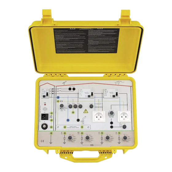
- Page 1 C.A 6710 Valise didactique "Installations Electriques" Demo case "Electrical Installation" F R A N Ç A I S Notice de fonctionnement User's manual E N G L I S H...
- Page 2 Dans la présente notice de fonctionnement, les instructions précédées de ce symbole, si elles ne sont pas bien respectées ou réalisées, peuvent occasionner un accident corporel ou endommager l’appareil et les installations. Vous venez d’acquérir une valise didactique "Installations Electriques" C.A 6710 et nous vous remercions de votre confiance. Pour obtenir le meilleur service de votre appareil : n Lire attentivement cette notice de fonctionnement, n Respecter les précautions d’emploi.
-
Page 3: Table Of Contents
English............................15 SOMMAIRE 1. PRESENTATION ........................................3 2. DESCRIPTION ........................................4 3. REGIMES DE NEUTRE ......................................5 Réseau TT ........................................ 5 Réseau TN ....................................... 6 Réseau IT ......................................... 6 4. MESURE DE RESISTANCE D’ISOLEMENT ................................ 7 Cas N°1 : Mesure de l’isolement sur résistance de 2 MΩ en parallèle avec une capacité... -
Page 4: Description
2. DESCRIPTION Figure 1 Dispositif différentiel de protection (10 mA) type A. Voyant rouge de polarité. Buzzer d’inversion phase - neutre Prise d’alimentation 230 V - 50 Hz (avec fusible accessible et fusible de rechange) Interrupteur de mise sous tension et Inverseur phase - neutre Prises de terre internes pour simulation des différents régimes de neutre et mesure de terre ou de résistivité... -
Page 5: Regimes De Neutre
3. REGIMES DE NEUTRE Figure 2 PRECAUTION IMPORTANTE : Cette valise a été conçue pour simuler des mesures sur différents types de réseaux électriques. Elle n’a pas été conçue pour recréer les défauts électriques pouvant apparaître sur ces réseaux. Ne pas faire de court-circuit entre phase, neutre et terre. -
Page 6: Réseau Tn
Réseau TN : Rappel : Ce type de schéma est par exemple utilisé dans les installations électriques tertiaires alimentées à partir d’un poste de transformation privé. Pour rappel, en régime TN, le neutre du transformateur privé est relié à la Terre et les masses de l’installation sont reliées au Neutre de ce poste. -
Page 7: Mesure De Resistance D'isolement
4. MESURE DE RESISTANCE D’ISOLEMENT CAS N°1 DDR 1 DDR 2 PR 1 PR 2 CAS N°2 Figure 3 Les mesures de résistance d’isolement sont possibles avec les appareils suivants : - C.A 6115N - C.A 6511/13 - C.A 6521/23/25/31/33 Cas N°1 : Mesure de l’isolement sur résistance de 2 MΩ... -
Page 8: Controle De Dispositif Differentiel
5. CONTROLE DE DISPOSITIF DIFFERENTIEL DDR1 DDR2 Figure 4 Les contrôles de dispositifs différentiels sont possibles avec les appareils suivants : - C.A 6115N - MX 4600 - CDA 10 Le CDA 10 est un testeur : il indique par des voyants le bon fonctionnement ou non du dispositif différentiel en fonction du calibre sélectionné. -
Page 9: Mesure De Terre Et De Resistivite
6. MESURE DE TERRE ET DE RESISTIVITE § 6.1 Résistivité § 6.2 Terre (méthode 1) Figure N°5 § 6.2 Terre Les mesures de terre sont possibles avec les appareils suivants : (méthode 2) - C.A 6115N - C.A 6421/23/25 - MX 4600 Les mesures de résistivités sont possibles uniquement avec le C.A 6425. -
Page 10: Mesure De Boucle
7. MESURE DE BOUCLE Figure 6 Les mesures de boucle sont possibles avec le C.A 6115N et le MX 4600. Mesures possibles : Résistance de boucle phase-neutre Impédance et résistance de boucle phase-terre Courant de court-circuit MESURE : Se placer en régime de neutre TT ou TN (voir § 3.1 et 3.2) . Si C.A 6115N, connecter l’appareil de mesure aux bornes de sécurité... -
Page 11: Mesure De Continuite
8. MESURE DE CONTINUITE Figure 7 Les mesures de continuité sont possibles avec les appareils suivants : - C.A 6115N - C.A 6511/13 - C.A 6521/23/25. MESURE : Connecter l’appareil de mesure entre les points W (borne de terre) et F (barrette de terre du bâtiment). - si C.A 6115N : utiliser le câble 3 cordons séparés et raccorder l’appareil sur les bornes de mesure avec le cordon L1/L et le cordon L2/N relié... -
Page 12: Simulation De Defauts
9. SIMULATION DE DEFAUTS Figure 8 Les Simulations de défauts possibles sont les suivantes : Coupure du neutre avec le poussoir fugitif K Coupure du PE / terre avec le poussoir fugitif L Coupure de la phase avec le poussoir fugitif M. Inversion neutre - terre (N - PE) avec le poussoir fugitif Q Courant de fuite réglable en reliant les deux bornes G (voir §... -
Page 13: Caracteristiques Techniques
10. CARACTERISTIQUES TECHNIQUES 10.1 Electriques Valeur caractéristiques : C = 5 µF ±10% Résistances pour simulation de résistance d’isolement sur circuit 2 MΩ // 5 µF R = 2 MΩ ±5% Tension maximale : 1200 V DC Entre L et N : R = 0,99 MΩ ±5% Résistances pour simulation de résistance d’isolement sur la prise centrale Entre L et PE : R = 26,8 MΩ... -
Page 14: Maintenance
Comme tous les appareils de mesure ou d’essais, une vérification périodique est nécessaire. Pour garantir une précision optimale, la valise didactique C.A 6710 doit être étalonnée et vérifiée au moins une fois par an. Cette opération s’effectue auprès de notre service Après-Vente. - Page 15 English Meaning of the symbol Warning ! Please refer to the user’s manual before using the instrument. In this User’s Manual, the instructions preceded by the above symbol, should they not be carried out as shown, can result in a physical accident or damage the instrument and the installations. Thank you for purchasing this C.A.
-
Page 16: Presentation
CONTENTS PRESENTATION ....................................... 2 DESCRIPTION ........................................3 NEUTRAL SYSTEMS ....................................... 4 TT network ........................................ 4 TN network ....................................... 5 IT network ......................................... 5 INSULATION RESISTANCE MEASUREMENT ............................... 6 Case 1: Measurement of insulation with a 2 MΩ resistance in parallel with a capacity of 5 µF (configuration of insulation measurement between conductors) ...................... -
Page 17: Description
2. DESCRIPTION Figure 1 Type-A differential protection system (10 mA). Red polarity LED. Phase-neutral inversion buzzer 230 V - 50 Hz power socket (with accessible fuse and spare fuse) Power on switch and phase-neutral inverter Internal earth sockets for simulation of the different neutral systems and earth or resistivity measurement (Caution: sockets not connected to the earth of the installation) Pushbutton for creating a phase-neutral or phase-earth leakage current between 4 and 34 mA 2 mains sockets (2P+E) -
Page 18: Neutral Systems
3. NEUTRAL SYSTEMS Figure 2 IMPORTANT PRECAUTION: This demo case has been designed to simulate measurement on various types of electrical networks. It has not been designed to recreate the electrical faults which may occur on these networks. Do not create short circuits between the phase, neutral and earth. -
Page 19: Tn Network
TN network Reminder: This type of system is used, for example, in tertiary electrical installations powered from a private transformer station. In a TN system, the neutral of the private transformer is connected to the ground and the earths of the installation are connected to the neutral of this transformer station. -
Page 20: Insulation Resistance Measurement
4. INSULATION RESISTANCE MEASUREMENT CASE N°1 DDR 1 DDR 2 PR 1 PR 2 CASE N°2 Figure 3 Insulation resistance measurements can be made using the following instruments: - C.A 6115N - C.A 6511/13 - C.A 6521/23/25/31/33 Case 1: Measurement of insulation with a 2 MΩ Ω Ω Ω Ω resistance in parallel with a capacity of 5 µF (configuration of insulation measurement between conductors) The 2 measurement terminals do not carry any voltage, even if the demo case is powered up and the input differential is set to I. -
Page 21: Checking Of Differential Device
5. CHECKING OF DIFFERENTIAL DEVICE DDR1 DDR2 Figure 4 The differential devices can be checked using the following instruments: - C.A 6115N - MX 4600 - CDA 10 The CDA 10 is a tester: it uses LEDs to indicate whether the differential device is operating correctly according to the calibre selected. -
Page 22: Earth And Resistivity Measurement
6. EARTH AND RESISTIVITY MEASUREMENT § 6.1 Resistivity § 6.2 Earth (method 1) Figure N°5 § 6.2 Earth The earth can be measured using the following instruments: (method 2) - C.A 6115N - C.A 6421/23/25 - MX 4600 Resistivity measurements are only possible with the C.A 6425. Resistivity measurement Connect terminals E, ES, S and H (previously X, Xv, Y and Z) of the measuring instrument to the corresponding terminals on the demo case which simulate rods stuck in the ground. -
Page 23: Loop Measurement
7. LOOP MEASUREMENT Figure 6 Loop measurements can be performed with the C.A 6115N and MX 4600. Measurements possible: Phase-neutral loop resistance Phase-earth loop impedance and resistance Short-circuit current MEASUREMENT: Set to the TT or TN neutral system (see § 3.1 and 3.2) . If C.A 6115N, connect the measuring instrument to the safety terminals H (with the cable with 3 separate leads) or to mains socket PR1 or PR2 (with the measurement cable fitted with a mains plug). -
Page 24: Continuity Measurement
8. CONTINUITY MEASUREMENT Figure 7 Continuity can be measured using the following instruments: - C.A 6115N - C.A 6511/13 - C.A 6521/23/25. MEASUREMENT: Connect the measurement instrument between points W (earth terminal) and F (earth bar of the building). - if C.A 6115N: use the cable with 3 separate leads and connect the instrument to the measurement terminals with lead L1/L and the L2/N lead linked to the L3/PE lead. -
Page 25: Fault Simulation
9. FAULT SIMULATION Figure 8 The following faults can be simulated: Cut-off of the neutral with the non-locking button K Cut-off of PE / earth with non-locking button L Phase outage with non-locking button M. Neutral earth (N - PE) inversion with non-locking button Q Adjustable leakage current by connecting the two terminals G (see §... -
Page 26: Technical Specifications
10. TECHNICAL SPECIFICATIONS 10.1 Electrical Characteristic values: Resistances for simulation C = 5 µF ±10% of insulation resistance on 2 MΩ // 5 µF circuit R = 2 MΩ ±5% Maximum voltage: 1200 V DC Resistances for simulation Between L and N: R = 0.99 MΩ ±5% of insulation resistance on central socket Between L and PE: R = 26.8 MΩ... -
Page 27: Maintenance
11.2 Calibration testing It is essential that all measuring instruments are regularly calibrated. For checking and calibration of your instrument, please contact our accredited laboratories (list on request) or the Chauvin Arnoux subsidiary or Agent in your country. Maintenance Repairs under or out of guarantee: please return the product to your distributor. - Page 28 12 - 2001 Code 689 425 A00 - Ed. 3 Deutschland : CA GmbH - Straßburger Str. 34 - 77694 Kehl / Rhein - Tel : (07851) 99 26-0 - Fax : (07851) 99 26-60 España : CA Iberica - C/Roger de Flor N° 293 - 08025 Barcelona - Tel : (93) 459 08 11 - Fax : (93) 459 14 43 Italia : AMRA MTI - via Sant' Ambrogio, 23/25 - 20050 Bareggia Di Macherio (MI) - Tel : (039) 245 75 45 - Fax : (039) 481 561 Österreich : CA Ges.m.b.H - Slamastrasse 29 / 3 - 1230 Wien - Tel : (1) 61 61 9 61 - Fax : (1) 61 61 9 61 61 Schweiz : CA AG - Einsiedlerstrasse 535 - 8810 Horgen - Tel : (01) 727 75 55 - Fax : (01) 727 75 56...
Need help?
Do you have a question about the C.A 6710 and is the answer not in the manual?
Questions and answers