
Subscribe to Our Youtube Channel
Related Manuals for Chauvin Arnoux C.A 8335


Summary of Contents for Chauvin Arnoux C.A 8335
- Page 1 C.A 8335 THREE-PHASE ELECTRICAL NETWORKS QUALISTAR PLUS ANALYSER ENGLISH Operating manual...
- Page 2 Thank you for purchasing this C.A 8335 energy analyser (Qualistar+). To obtain the best service from your unit: Read these operating instructions carefully, Comply with the precautions for use. Meaning of the symbols used on the unit: CAUTION - DANGER! Read the User Manual USB socket The CE marking guarantees conformity with European directives and with regulations covering EMC.
- Page 3 MEASUREMENT CATEGORIES Definition of measurement categories according to the IEC standard 61010-1: CAT I: Measurement category I corresponds to measurements taken on circuits not directly connected to the network. CAT II: Measurement category II corresponds to measurements taken on circuits directly connected to the installation. Example: measurement for electrodomestic units, portable tools and analogue devices CAT III: Measurement category III corresponds to measurements on building installations.
-
Page 4: Table Of Contents
13. USE ..............53 5. KEY WAVEFORM CAPTURE..... 17 13.1 Start-up............... 53 5.1 Available sub-modes .......... 17 13.2 Configuration of the C.A 8335 ......53 Transient mode ......... 17 13.3 Installation of leads ..........54 Inrush current mode ........19 13.4 Transient/Inrush recording ...... - Page 5 17.4 Diagram of the 4 quadrants........ 67 17.5 Mechanism for triggering transient sensors..68 17.6 Sensor conditions in Ringing Current mode..68 17.7 Glossary ............. 69 18. TO ORDER............70 18.1 C.A 8335 power analyser ........70 18.2 Accessories ............70 18.3 Spare parts............70...
-
Page 6: Introduction
1. INTRODUCTION The C.A 8335 (Qualistar+) is a three-phase AC+DC Voltage and current minimum and maximum half- 1000 V category III or 600 V category IV period values (IEC 61010-1) graphic display network analyser. Peak values for voltages and current (neutral... -
Page 7: Presentation
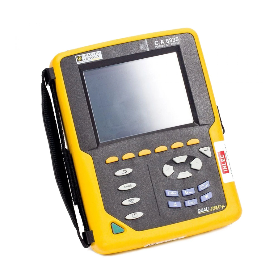
When it starts, the C.A 8335 displays the Waveform screen automatically. Information on this screen can be found chapter 7, page Figure1: C.A 8335 (Qualistar+) general view Item Function See para. -
Page 8: Keypad Keys
3.3.2 Icons The display uses the following icons: 3.4 Keypad keys Icon Designation 3.4.1 Function keys (yellow keys) Phase to neutral voltage mode These 6 keys activate the function or told represented by the corresponding icon on the screen (See para Simple current mode 3.3.2) Power mode... -
Page 9: Connectors
Located along the upper section, these connectors are distributed as follows: Battery charged Low battery Mobile bars: battery charging The C.A 8335 is powered by the mains and pre-charged. When the capacity of the battery is too low, the following message is displayed: Figure 3: upper connectors... -
Page 10: The Stand
For completely empty batteries, the charge takes 5 Active, reactive (capacitive and inductive) and hours app. As soon as the battery is recharged, the unit apparent power by phase and cumulative (excluding continues to use mains power without discharging the neutral). -
Page 11: Abbreviations
3.9 Abbreviations Tangent. Total harmonic distortion. Meaning of symbols and abbreviations used: Phase to Phase voltage crest factor Unit Designation Phase to phase voltage harmonic Alternative and continuous components phase to phase Urms True effective voltage Alternative component alone hase to phase Uthd Total p voltage harmonic... -
Page 12: Configuration Key
4. CONFIGURATION KEY This key configures the CA 8335. This allows the user Erase memory Choice of total or partial 4.11 to pre-define set ups and configuration of the deletion of data instrument. Set ups and configuration are stored in non- volatile memory and is retained after switching off the About Serial number, software... -
Page 13: Colours
Calculation methods Defines the use or non-use of harmonics in calculating reactive parameters (powers and energies). Figure 8: the Contrast/Brightness menu The selected field is highlighted in yellow. To modify the contrast, press SUCM To move to the next field, press Figure 10: the Calculation methods menu To change the brightness, press To select With harmonics or Without harmonics,... -
Page 14: Trend Mode
Displacement power factor. Trend mode Crest factor of phase to phase voltage (2φ, 3φ). The C.A 8335 has a recording function – key- (see chapter 9, page 43) for recording measured and Crest factor of line-to-neutral voltage. calculated values (Urms, Vrms, Arms, etc.). Four independent set ups may be configured depending on Crest factor of current. -
Page 15: Alarm Mode
Specific features for the last two lines These are set out below: Figure 14: These two lines involve harmonics These two lines involve the recording of VAh, Ah, Vh and Uh variable harmonics. You can select the ranks of harmonics to be recorded (between 0 and 50) for each of these harmonics and possibly only odd harmonics SUMA00 within this range. -
Page 16: Deleting Data
4.12 Information 4.11 Deleting data This screen displays the unit serial number, the Partially or totally deletes the data recorded in the unit firmware version, the loader version, the basic card (rend, Transient, Inrush, Alarm, Snapshot recordings version, the CPLD (Complex Programmable Logic and Set ups). -
Page 17: Key Waveform Capture
5. KEY WAVEFORM CAPTURE This mode enables the Transient and Inrush current to be displayed and recorded. 5.1 Available sub-modes The sub-modes are listed in the screen below and covered individually in the following paragraphs. WFC01 Figure 19: the Programming a search screen in Transient mode. - Page 18 Arrows appear. Choose the value with the keys and then confirm by pressing Proceed in the same way for the Current threshold, Number and Series name fields. 5.2.1.2 STAGE 2: start of programming To begin monitoring between the start and stop times which you have defined press the yellow keypad key for the OK icon.
-
Page 19: Inrush Current Mode
Item Function two sub-menus, , are available (See para 5.3.2). The C.A 8335 keeps in memory only a Selection of graphs to be displayed. single current waveform capture. - 4 V: displays the 4 single voltages during the transient (here in a 5-wire triphase Note: when Inrush current mode is started the connection). - Page 20 OK icon (bottom right of screen) is displayed again. WFI00 Note: the C.A 8335 can keep in memory only a single current waveform capture. If you wish to make another capture firstly delete the previous one. Figure 24: the Programming the capture screen in...
- Page 21 • RMS value of the half-period (or lobe) of the Instantaneous measurement cursor at a point current on which the cursor is positioned. in the graph. Use the keys to move the • Maximum half-period RMS value of the current cursor.
- Page 22 5.3.4.2 The PEAK display screen in A3 5.3.4.1 The PEAK display screen in 3A Information is displayed as follows: The screen of 3A filter appears only when the waveforms are displayed. Information is displayed as follows: WFI05 Figure 29: the PEAK display screen in A3 Item Function WFI04...
-
Page 23: Harmonics
6. HARMONICS This mode displays a realtime representation of the Single voltage harmonics rates of the voltage, current and apparent power for each rank. It enables the harmonic currents This sub-menu displays the harmonics of the voltage. produced by the non-linear charges to be determined, problems engendered these... - Page 24 Battery charge level. Item Function This information is relative to the harmonic under the cursor (Figure 32, item 3). Vh 03: number of harmonic. The horizontal axis indicates the ranks of the rate harmonic relative harmonics (uneven marking). fundamental value. Display of the level of the harmonics as a V: effective voltage of the harmonic in percentage relative to the fundamental value...
-
Page 25: Current
Current Harmonic ranks selection cursor. Use the keys to move the cursor. This sub-menu displays the harmonics of the current. Display of expert mode (triphase connection 6.3.1 The current harmonics display screen in 3L only - See para 6.6) of the 3 x 3L phases, or of L1, L2 and L3 (*). -
Page 26: Apparent Power
Item Function Reminder of the mode used Instantaneous frequency. The horizontal axis indicates the ranks of the This information is relative to the harmonic harmonics (uneven marking). under the cursor (Figure 35, item 7). Display of the level of the harmonics as a Vah03: number of harmonic. -
Page 27: Composite Voltage
6.4.1.1 The display screen of the apparent power Harmonic ranks selection cursor. Use the harmonics in L1 keys to move the cursor. The information is: Display of expert mode (triphase connection only - See para 6.6) of the 3 x 3L phases, or of L1, L2 and L3 (*). -
Page 28: Expert Mode
Current date and time. Item Function Battery charge level. This information is relative to the harmonic under the cursor (Figure 38, item 3). Uh 03: number of harmonic. rate harmonics relative fundamental harmonic. The horizontal axis indicates the ranks of the harmonics (uneven marking). - Page 29 6.6.1 The screen displaying expert mode for line voltage This sub-menu displays the influence of the harmonics of the line voltage on the heating of the neutral or on the rotating machines. Information is displayed as follows: MHA09 Figure 39: the expert mode screen for phase voltage Item Function Harmonics inducing a negative sequence.
-
Page 30: Waveform
7. WAVEFORM • Single-phase: no choice (L1) This mode enables the current and voltage graphs to be • Diphase: 2V, 2A, L1, L2 displayed, together with the values measured and • Triphase 3 or 4 wires: 3U, 3V, 3A, L1, L2, L3 calculated from the voltages and currents (except for power, energy and harmonics). - Page 31 7.2.3 The RMS display screen in 4A Instantaneous value of the signals at the intersection of the cursor (Figure 42, item 7) This screen displays the three phase currents and the and of the graphs. neutral current of a triphase system. t: time relative to the start of the period The displayed information is read as follows: (expressed in milliseconds).
- Page 32 The displayed information is read as follows: The displayed information is read as follows: WF04 WF05* Figure 46: the THD display screen in 3U Figure 45: the RMS display screen for neutral Item Function Item Function Reminder of the mode used Axis of voltage values of current and of voltage with automatic scaling.
-
Page 33: Measurement Of Total Harmonic Distortion32 7.4 Measurement Of The Peak Factor
The displayed information is read as follows: 7.3.2 The THD display screen in 3V This screen displays the waveforms of a period of the line voltages and the total harmonic distortion rates. The displayed information is read as follows: WF07* Figure 48: the THD display screen in 3A CW07* Item... - Page 34 The displayed information is read as follows: The displayed information is read as follows: WF08 WF09 Figure 49: the CF display screen in 3U Figure 50: the display screen in 3V Item Function Item Function Reminder of the mode used Peak factor for each graph.
-
Page 35: Measurement Of Extreme And Average Voltage And Current Values
Instantaneous value cursor. To move the MAX: RMS value of the maximum phase to cursor use the keys. phase voltage from starting of the C.A 8335 or from the last time the key is pressed. Instantaneous values of the signals at the... - Page 36 MIN: RMS value of the minimum line voltage MIN: minimum RMS value of the current from from starting the C.A 8335 or from the last starting the C.A 8335 or from the last time the time the key is pressed.
-
Page 37: Simultaneous Display
RMS : true effective value of voltage. MIN: minimum RMS value of the voltage from starting the C.A 8335 or from the last time the key is pressed. PEAK+: maximum peak value of the voltage. PEAK-: minimum peak value of the voltage. - Page 38 The displayed information is read as follows: THD: total harmonic distortion rate. DF: distortion factor. CF: peak factor calculated in relation to the displayed waveform. KF: K factor. Enables correct sizing of Transformers to compensate for overheating caused by harmonics. Column of RMS value relative to neutral.
-
Page 39: Display Of Fresnel Diagram
7.7.3 The screen Displaying the Fresnel diagram Display of Fresnel diagram in 3A This sub-menu displays the absolute values of the This screen displays the absolute value of the current at voltages and currents at the fundamental frequency, the fundamental frequency, the phase angle of the currents phase angle of the voltages relative to the currents and relative to one another and the unbalance of the the unbalances of the voltages and currents. -
Page 40: Key
8. ALARM MODE This mode detects over thresholds (Vrms, Urms, Arms, PST, Vcf, Ucf, Acf, Vunb, Aunb, Hz, KF, Vthd, Uthd, Athd, Vdf, W, VAR, VA, DPF, PF, Vh, Uh, Ah and VAh) of values that you wish to monitor. You must firstly select a hysteresis value that is valid for all alarms. -
Page 41: Programming An Alarm Campaign
values. The arrows appear in the date and time Hysteresis value (corresponds to the field of the programming campaign start. added or cut percentage of the chosen alarm threshold that shall stop the Press to increment or decrement a value and alarm if exceeded –... -
Page 42: Deleting The Alarm Log
The following data is displayed: AM02 Figure 67: Alarm log in deletion mode screen AM01 Figure 66: Alarm log screen Item Function Alarm date and time. Alarm log memory capacity. The black cursor corresponds to used memory. Alarm source. Monitored parameter (Vrms, etc.). Amplitude (min. -
Page 43: Trend Mode
9. TREND MODE This mode records the parameter changes previously specified by the Configuration / Trend mode screen (See para 4.9, p 14). 9.1 Available sub-menus Sub-menus are listed on the screen below and mentioned one-by-one in the following paragraphs. Sub-menus are selected using the yellow keys on the keypad under the screen. -
Page 44: Trend Mode Configuration
name (no more than 8 characters). Several recordings can carry the same name. Available alphanumeric characters are A...Z, space and 0 to 9. Use keys to display a character to switch to the contiguous character. 7. Press to validate the name. 9.2.2 STAGE 2: Start programming a recording. -
Page 45: Displaying Recording List
Reminder: You can record the following values: To select the first harmonic rank: The field is highlighted in yellow. Press . Arrows appear. Unit Designation Select the rank from which harmonics shall be recorded via , then validate via Urms Effective phase to phase line voltage (2φ, Press to switch to the following field. -
Page 46: Deleting Recordings
Recording name. Recording start time. Recording end time. Deleting recordings This submenu is used to deleted recordings. Perform the following: 1. Select the submenu by pressing the icon’s yellow key. 2. Select the recording to be deleted via . The selected field is in boldface. -
Page 47: Power And Energy Key
10. POWER AND ENERGY KEY 10.2.1 The Energy consumed display for the 3 This key displays measurements for power and phases (3L) energies. This screen displays the following information: 10.1 Available sub-menus Sub-menus are listed on the screen below and mentioned one-by-one in the following paragraphs. -
Page 48: Energy Generated
VARh Reactive energy consumed: Inductive. Capacitive. Apparent power (total if 3φ) Apparent energy consumed. Power factor. Displacement power factor. MPE04 Figure 79: the Energy generated display for the 3 Tangent. phases (3L) Note: The information displayed for filters L2 and L3 is Unit Designation identical to the information described above, but relates... -
Page 49: Start Of Energy Metering
10.6 Zero resets of energy Power factor. metering Displacement Power factor. To reset metering, press the yellow key on the keypad Tangent. with the icon and the key to confirm. All energy values (consumed and generated) are reset. Note: the information displayed for filters L2 and L3 is identical to the information described above, but relates Note: refer to the diagram of the 4 quadrants for powers to phases 2 &... -
Page 50: Screen Snapshot Key
Figure 83: example of the display of a list of screen The active mode icon will re-appear when you release snapshots key: the C.A 8335 has saved the image. Item Function Reminder: the Qualistar+ can save a maximum of 50 screen snapshots. - Page 51 11.2.3 View of a snapshot from the list 11.2.4 Deletion of a snapshot from the list To display a snapshot, proceed as follows: To delete a snapshot, proceed as follows: 1. From the list of snapshots (see Figure 83 for 1.
-
Page 52: Help Key
12. HELP KEY key provides information on the functions and symbols used for the current display mode. Information is displayed as follows: HELP Figure 84: example of the help page for the power and energy mode, page 1 Item Function Reminder of the mode used Reminder of the current mode. -
Page 53: Use
Configuration screen. WF22 Figure 86: waveform screen The C.A 8335 is battery operated only if the battery is adequately charged. If the battery is not adequately charged, the alarm message "Low battery, the device will cease operating shortly" will appear (See para 3.6, p 9). -
Page 54: Installation Of Leads
(MN clamp, C clamp, AmpFLEX™, PAC clamp, etc.). Figure 92: 5-wire three phase connection 5 voltage input connectors Connect the measuring leads to the C.A 8335 as 13.4 Transient/Inrush recording follows: Current measurement: 4-point connector (item 1). Do Reminder: all screens can be saved (screen snapshot) -
Page 55: Alarm Recording
Press the key to turn the C.A. 8335 off. 13.7.4 Manual cut-off The C.A 8335 may not be turned off during recording (See para 9.2.2, page 44) without confirmation. The Use the function in accordance with paragraph 8.3.3, following message will appears: page 41. -
Page 56: Maintenance
14.7 Updating of the internal software Do not use any solvents. The internal software of the C.A 8335 may be updated 14.4 Replacing the screen film using the A-B type USB lead supplied with the device... -
Page 57: General Specifications
15.2.2 Battery supply must only be used with the "battery" OR with The C.A 8335 may be used without any connection to supplied power - the simultaneous use of the the mains supply. The battery also enables the use of battery AND the supplied power for the device is the Qualistar+ in power cuts. -
Page 58: User Safety
Voltage interruption (as per IEC 61000-4-11) 15.3.2 Mechanical conditions Gravity: 100% loss over a supply period According to IEC 61010-1, the C.A 8335 is considered Sanctions: CRITERION A as a MOBILE DEVICE (HAND-CARRIED). 15.3.3.2 Emission as per NF EN 61326 - 1 A3 Operating position: indifferent. -
Page 59: Functional Characteristics
16. FUNCTIONAL CHARACTERISTICS 16.1 Reference Conditions This table indicates reference conditions for sizes to be used by default in the characteristics indicated in paragraph 16.2.4. Parameter Reference Conditions 23 °C ± 3 K Ambient temperature Humidity (relative humidity) [ 45 % ; 75 % ] Atmospheric pressure [860 hPa;... - Page 60 Maximum error in Measurement scope Display Measuring resolution field of reference Minimum Maximum ±(1 pt) Frequency 40 Hz 69 Hz 0.01 Hz 0.1 V ±(0.5 % + 2 pts) Phase voltage V < 1000 V 10 V 1,000 V TRMS ±(0.5 % + 1 pt) V ≥...
- Page 61 Measurement scope Maximum error Display Measuring resolution the field of reference Minimum Maximum 0.1 V V < 1000 V Phase voltage TRMS ± (0.8 % + 1 V) 10 V 1,000 V half-period V ≥ 1000 V 0.1 V U < 1000 V Composite voltage TRMS ±...
- Page 62 Measurement scope Maximum error Display Measuring resolution the field of reference Minimum Maximum ± (1 %) Excluding Cos φ ≥ 0.8 AmpFLEX™ 0 Wh 9999 MWh 4 digits ± (1,5 %) & 0,2 ≤ Cos φ < 0.8 MiniFLEX Active ±...
- Page 63 The RMS current measurement error and phase error 16.2.5 Current sensor characteristics (after correspond to additional errors (added to device errors) linearisation) indicated as parameters for the calculations carried out Sensor errors are offset by typical correction inside the by the analyser (power, energy, power factors, device.
-
Page 64: Appendices
17. APPENDICES This chapter presents the mathematical formulae used 17.1.3 Minimum and maximum half-cycle efficient for calculating different parameters for C.A.8335. values (excluding neutral) Vmax max( Vdem , Vmin min( Vdem 17.1 Mathematical formulae Umax max( Udem , Umin min( Udem i 17.1.1 Network frequency and sample Amax... - Page 65 Efficient composite voltage phase i+1 17.1.9 Harmonic distortions (ex neutral) − NechSec ∑ ⋅ Two global values giving the relative quality of Urms i U i n NechSec harmonics are calculated: The THD in proportion of the fundamental and the DF in proportion to the RMS value. Efficient current phase i+1 [ ][ ] [ ][ ]...
-
Page 66: Hysteresis
[ ][ ] ∑ 17.1.12 Different rates (ex neutral) 3600 Tint PF = Power Factor phase i +1 Generated apparent power phase i+1 φ [ ][ ] ∑ Displacement Power factor 3600 Tint phase i +1 φ Tangent phase i +1 Generated inductive reactive power phase i+1 ∑... -
Page 67: Minimum Scale Values For Waveforms And Minimum Rms Values
17.3 Minimum scale values for waveforms and minimum RMS values Type of current sensor Min RMS current value [A] Min scale value for current [A] AmpFLEX 6500 A ™ MiniFLEX 6500 A PAC93 1000 A clamp C193 1000 A clamp MN93 200 A clamp MN93A 100 A clamp MN93A clamp probe 5 A... -
Page 68: Mechanism For Triggering Transient Sensors
17.5 Mechanism for triggering transient sensors The sample rate is a constant 256 samples per cycle. When a transient recording is started, each sample is compared to the sample from the preceding cycle. The preceding cycle defines the mid-point of the trigger envelope and is used as a reference. -
Page 69: Glossary
Temporary surge at industrial frequency: temporary 17.7 Glossary increase in the voltage amplitude at a point in the electrical power network above a given threshold. Ampere: unit of electrical current intensity (A symbole). Nominal voltage: Reference voltage of a network. Bandwidth: the analogue frequency of a signal. -
Page 70: To Order
18. TO ORDER 18.1 C.A 8335 power analyser 18.3 Spare parts Black banana-banana right-right Please consult C.A 8335 alone P01 1605 77 security cables C.A 8,335 MN P01 1605 71 Black crocodile clamps. Please consult C.A 8335 MN93A P01 1605 72 C.A 8335 AMP450... - Page 71 Tel: +86 21 65 21 51 96 - Fax: +86 21 65 21 61 07 SCANDINAVIA - CA Mätsystem AB USA - Chauvin Arnoux Inc - d.b.a AEMC Instruments Box 4501 - SE 18304 TÄBY 200 Foxborough Blvd. - Foxborough - MA 02035...
Need help?
Do you have a question about the C.A 8335 and is the answer not in the manual?
Questions and answers