Table of Contents
Advertisement
Quick Links
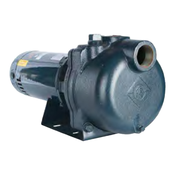
OWNER'S MANUAL
Turf Boss 1-2 HP
The 1-2 HP Turf Boss serves a wide array of applications mov-
ing high volumes of water, including timer-operated irriga-
tion systems, residential water transfer, commercial
dewatering, rainwater drainage, light agricultural irrigation,
sump drainage, and industrial liquid transfer. As a premium
self-priming sprinkler pump, the Turf Boss is approved for
indoor or outdoor operation through CSA and UL.
This product is covered by a limited warranty for a period of 1
year from the date of original purchase by the consumer. For
complete warranty information, refer to www.FranklinWater.com.
Specifications
Pumps
Model
FTB1CI
FTB15CI
FTB2CI
FTB1CI-SSI*
FTB15CI-SSI*
FTB2CI-SSI*
FTB1CI-SSI-T*
FTB15CI-SSI-T*
FTB2CI-SSI-T*
Pump Ends
Model
FTB1CI-PE
FTB15CI-PE
FTB2CI-PE
FTB1CI-SS1-PE*
FTB15CI-SSI-PE*
FTB2CI-SSI-PE*
*Stainless steel impeller
HP
Phase
Discharge (in)
1
1.5
2
1
1
1.5
2
1
1.5
3
2
HP
Suction x Discharge (in)
1
1.5
2
1
1.5
2
Suction x
1½ x 1½
208-230/460
1½ x 1½
Volts
Weight (lb)
115/230
230
115/230
230
60
Weight (lb)
28
30
50
57
58
52
59
51
55
57
Advertisement
Table of Contents

Related Manuals for Franklin Electric Turf Boss FTB1CI-SSI Series


Summary of Contents for Franklin Electric Turf Boss FTB1CI-SSI Series
- Page 1 OWNER'S MANUAL Turf Boss 1-2 HP The 1-2 HP Turf Boss serves a wide array of applications mov- ing high volumes of water, including timer-operated irriga- tion systems, residential water transfer, commercial dewatering, rainwater drainage, light agricultural irrigation, sump drainage, and industrial liquid transfer. As a premium self-priming sprinkler pump, the Turf Boss is approved for indoor or outdoor operation through CSA and UL.
-
Page 2: Safety Instructions
Failure to comply with national and local electrical and plumbing codes and within Franklin Electric recommendations may result in electrical shock or fire hazard, unsatisfactory performance, or equipment failure. -
Page 3: Typical Installation
INSTALLATION Typical Installation INSTALLATION Typical Installation 1. Pipe plug 2. To sprinkler system 3. Discharge port 4. Well seal 5. Adapter 6. Foot valve 7. Drain plug 8. Suction port Shallow Well Installations 1. To pump Single Multiple 2. Check valve 3. -
Page 4: Pump Location
INSTALLATION Pump Location Pump Location • Install the pump in a clean, dry, and ventilated location shielded from direct sun and precipitation. • Provide adequate room for future servicing, protection from freezing temperatures, flooding, and equipment drainage. • Bolt unit down evenly on a good foundation, preferably concrete, to prevent unnecessary stresses from pump movement. -
Page 5: Operation
OPERATION Electrical Connections 3. Install a proper fused disconnect switch in the line. • Make sure the correct gauge of cable is used to carry the load. IMPORTANT: Undersized wire between the motor and the power source will adversely limit the starting and load carrying abilities of the motor. -
Page 6: Maintenance
MAINTENANCE Draining the Pump 5. Gradually open the discharge valve to the halfway point. • If the pump does not deliver water within seconds, stop the motor and prime pump again. • Several starting attempts may be necessary to expel all air from the pump and suction lines. 6. - Page 7 MAINTENANCE Reassembly Reassembly 1. Insert a new stationary portion of the mechanical seal into the motor adapter. • Ensure the bracket socket is clean before installation. • Lubricate bracket ID (internal diameter) with P-80 lubricant to ease installation. • Do not contaminate the seal face. 2.
-
Page 8: Troubleshooting
Pump, motor, or piping loose ported. Water leakage at pump Defective seal assembly Replace seal. shaft For technical assistance, parts, or repair, please contact: 800.348.2420 | franklinwater.com Copyright © 2022, Franklin Electric, Co., Inc. All rights reserved. 106258101 Rev. 007 10/22...
Need help?
Do you have a question about the Turf Boss FTB1CI-SSI Series and is the answer not in the manual?
Questions and answers